Datasheet
Year, pagecount:2022, 2 page(s)
Language:English
Downloads:2
Uploaded:September 26, 2022
Size:1 MB
Institution:
-
Comments:
Attachment:-
Download in PDF:Please log in!
Comments
No comments yet. You can be the first!Most popular documents in this category


Content extract
Gearshift Load Cells for race applications. High performance race vehicles require fully optimized setup to gain a maximum advantage. One such example is when changing gear the driver or rider needs to have very fast reactions to minimize the time that it takes to change gear. Traditionally one would depress the clutch and lift off the throttle a little to make the gear shift. This all takes time and even the best drivers still take a second or two to make the shift. Just think if you could save some of this time and not have to lift off the throttle how much further would you have travelled?. One method is to have what is called a full throttle gear change, where the driver maintains the throttle position and does not depress the clutch pedal at all. The engine is pushing full power at all times. How is this done?. A load sensor or load cell as we call them is fitted to the gear change lever or in the control rod between the lever and the gearbox. When the driver moves the lever in
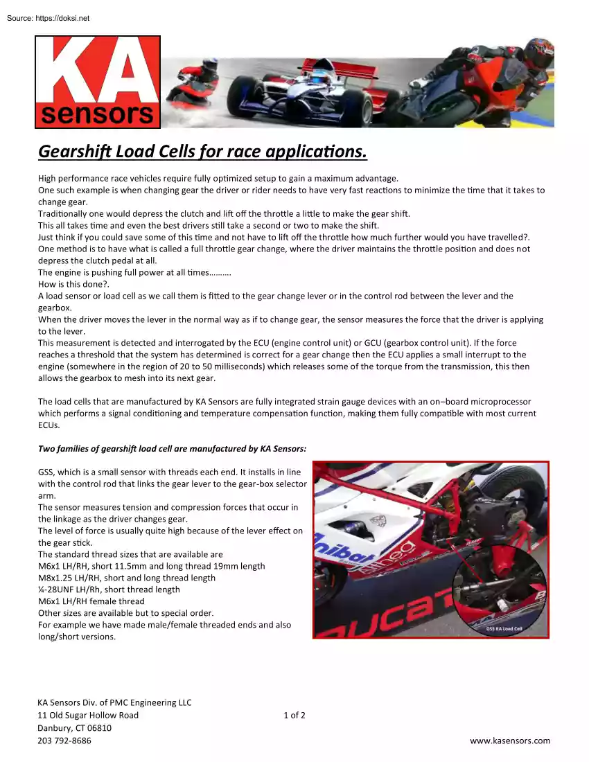
the normal way as if to change gear, the sensor measures the force that the driver is applying to the lever. This measurement is detected and interrogated by the ECU (engine control unit) or GCU (gearbox control unit). If the force reaches a threshold that the system has determined is correct for a gear change then the ECU applies a small interrupt to the engine (somewhere in the region of 20 to 50 milliseconds) which releases some of the torque from the transmission, this then allows the gearbox to mesh into its next gear. The load cells that are manufactured by KA Sensors are fully integrated strain gauge devices with an on–board microprocessor KA Sensors Loadfunction, Cell making them fully compatible with most current which performs a signal conditioning andGSS temperature compensation ECUs. Two families of gearshift load cell are manufactured by KA Sensors: GSS, which is a small sensor with threads each end. It installs in line with the control rod that links the gear lever to
the gear-box selector arm. The sensor measures tension and compression forces that occur in the linkage as the driver changes gear. The level of force is usually quite high because of the lever effect on the gear stick. The standard thread sizes that are available are M6x1 LH/RH, short 11.5mm and long thread 19mm length M8x1.25 LH/RH, short and long thread length ¼-28UNF LH/Rh, short thread length M6x1 LH/RH female thread Other sizes are available but to special order. For example we have made male/female threaded ends and also long/short versions. KA Sensors Div. of PMC Engineering LLC 11 Old Sugar Hollow Road Danbury, CT 06810 203 792-8686 1 of 2 www.kasensorscom GST, this is the sensor which fits onto the top of the gear shift lever. With its associated cover forms the contact point that the driver uses to change gear (Gear knob). This sensor measures the forward and reverse direct force applied by the driver when changing gear, it will not measure the sideways force such as
is seen on a H pattern gear-box. GST KA Load Cell The force required to change gear is not usually very high, in the order of 50 – 200N would be quite normal. Typically we would scale the sensor to a range of +/-250N which should give enough resolution on most systems. Different ranges from +/-150N to +/-1000N can be made to suit specific installations. The sensor fits onto the lever by screw thread. Standard thread is: M10x1.5 Other threads available are: M12x1.75 9/16-18UNF For other special sizes please ask. There are four standard covers which fit over the sensors body and are held on with a single machine screw. Aluminum type, Dome or straight. Nylon type, dome or straight. When installing the sensor onto the gear stick it is important to take into GSS Sensors Load Cell account the length of the sensor which will addKA a little over 3 inches to the length of the lever, so it may be necessary to cut the lever down a little to maintain the normal shifting position. On both types
of sensor the output is an analog voltage 0.5 to 45V with a 25V zero load value The usual setup is to have the increasing voltage from 2.5V to 45V as the up shift reading and the 25V to 05V as the downshift reading. Supply voltages are selected at time of order as either 5V ratiometric from the ecu or an 8-16V un-regulated voltage, typically used is the vehicle battery supply. The actual choice of sensor is down to either personal choice or more often the installation. The GSS is the best option if you can get access to the gearbox control rod. This is because the sensor will be positioned out of harms way and the control rod will be much easier to machine than the gear-lever itself which is usually hardened steel. If the control rod is positioned in a tight space or sometimes in the engine bay where the temperature can be extremely hot then the best option may be to use the GST sensor on the lever top. We can offer assistance with the choice if one is not certain about the best
solution. Some race series mandate the use of paddle shift for gearshift, this means that the gearshift load cell is not required. However other series such as WRC do not allow paddle shift and therefore the market for gearshift sensors is there. Some of our customers for the gearshift load cells include: Sequential gearbox makers, Motorcycle race teams and builders, Rally, GT, LMP, Touring cars, Drift cars, Drag cars, Fast high performance road cars will be a good source of potential users of sequential gearboxes and hence load cells. KA Sensors Div. of PMC Engineering LLC 11 Old Sugar Hollow Road Danbury, CT 06810 203 792-8686 2 of 2 www.kasensorscom
 When reading, most of us just let a story wash over us, getting lost in the world of the book rather than paying attention to the individual elements of the plot or writing. However, in English class, our teachers ask us to look at the mechanics of the writing.