Datasheet
Year, pagecount:1999, 70 page(s)
Language:English
Downloads:2
Uploaded:June 26, 2023
Size:1 MB
Institution:
[USC] University of Southern California
Comments:
Attachment:-
Download in PDF:Please log in!
Comments
No comments yet. You can be the first!


Content extract
Source: http://www.doksinet RECOMMENDED PROCEDURES FOR IMPLEMENTATION OF DMG SPECIAL PUBLICATION 117 GUIDELINES FOR ANALYZING AND MITIGATING LIQUEFACTION IN CALIFORNIA SC EC Organized through the Southern California Earthquake Center University of Southern California Source: http://www.doksinet RECOMMENDED PROCEDURES FOR IMPLEMENTATION OF DMG SPECIAL PUBLICATION 117 GUIDELINES FOR ANALYZING AND MITIGATING LIQUEFACTION HAZARDS IN CALIFORNIA Implementation Committee: G.R Martin and M Lew Co-chairs and Editors K. Arulmoli, JI Baez, TF Blake, J Earnest, F Gharib, J Goldhammer, D Hsu, S. Kupferman, J O’Tousa, CR Real, W Reeder, E Simantob, and TL Youd Committee Members March 1999 SC EC Organized through the Southern California Earthquake Center University of Southern California Source: http://www.doksinet Recommended Procedures for Implementation of DMG Special Publication 117 Guidelines for Analyzing and Mitigating Liquefaction Hazards in California This document was funded
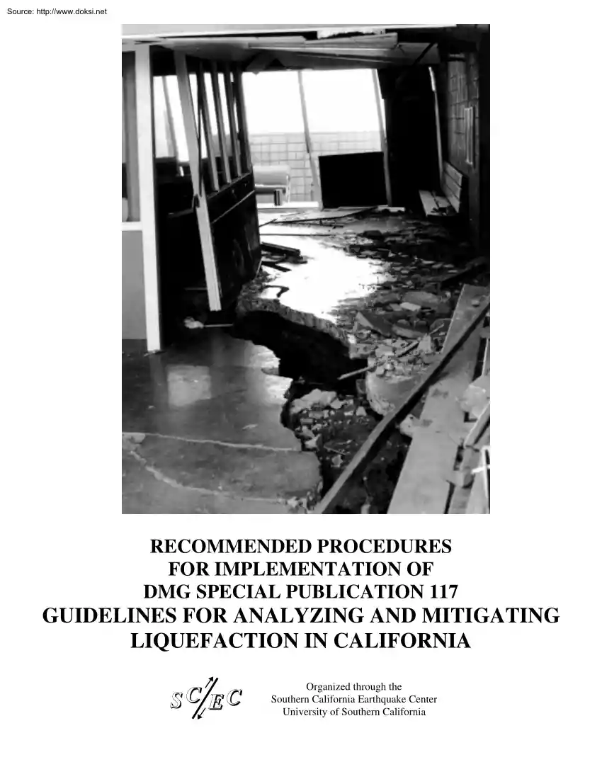
by the Southern California Earthquake Center. SCEC is funded by NSF Cooperative Agreement EAR-8920136 and USGS Cooperative Agreements 14-08-0001A0899 and 1434-HQ-97AG01718. The SCEC contribution number for this paper is 462 Cover page photograph of L.A County Juvenile Hall, Sylmar, California damaged by liquefaction during the San Fernando earthquake of February 9, 1971, was provided by Jack Meehan, Structural Engineer. Title page photograph of Marine Research Facility at Moss Landing, California, damaged by liquefaction during the Loma Prieta earthquake of October 17, 1989, was provided by Prof. T L Youd of Brigham Young University. The publication costs of this report were supported by the Larwin Company, Lennar Communities, and the Newhall Land and Farming Company. ii Source: http://www.doksinet Recommended Procedures for Implementation of DMG Special Publication 117 Guidelines for Analyzing and Mitigating Liquefaction Hazards in California TABLE OF CONTENTS TABLE OF CONTENTS .
iii ACKNOWLEDGMENTS.v 1.0 INTRODUCTION1 2.0 ESTABLISHMENT OF “LIQUEFACTION HAZARD ZONES”3 3.0 Roles of engineering geologists and geotechnical engineers4 4.0 PRELIMINARY SCREENING FOR LIQUEFACTION5 5.0 FIELD INVESTIGATIONS 6 5.1 Geologic Reconnaissance6 5.2 Subsurface Explorations6 5.3 Depth of Analysis for Liquefaction Evaluation7 5.4 Liquefaction Assessment by Use of the Standard Penetration Test (SPT)7 5.41 Introduction7 5.42 Drilling Method8 5.43 Hole Diameter8 5.44 Drive-Rod Length9 5.45 Sampler Type9 5.46 Energy Delivery 9 5.47 Spatial Frequency of Tests9 5.48 SPT Testing in Gravel Deposits10 5.5 Liquefaction Assessment by Use of the Cone Penetration Test (CPT) 14 5.6 Liquefaction Assessment Using Other In Situ Indices16 5.7 Overburden Corrections For Differing Water Table Conditions 16 6.0 GROUND MOTIONS FOR LIQUEFACTION ANALYSES 17 6.1 Ground Motion Determination17 6.2 Site-Specific Development of Peak Ground Acceleration and Magnitude 18 6.3 Standardized Ground-Motion Maps
from CDMG 20 7.0 EVALUATION OF LIQUEFACTION HAZARDS .22 7.1 Liquefaction Potential22 7.2 Use of Site-Specific Response Analyses 23 7.3 Hazard Assessment24 7.4 Flow Slides26 7.5 Lateral Spreads 26 7.51 The Bartlett and Youd Empirical Approach27 7.52 Analytical Approaches 27 7.6 Settlement28 7.61 Background 28 7.611Saturated Sand28 7.612Dry Sand 29 iii Source: http://www.doksinet Recommended Procedures for Implementation of DMG Special Publication 117 Guidelines for Analyzing and Mitigating Liquefaction Hazards in California 7.7 7.8 7.9 7.62 Recommended Methods for Saturated and Dry/Unsaturated Sands29 7.63 Settlement of Silty Sand and Silt 29 7.64 Clayey Sand30 7.65 Settlement of Layered Deposits 31 7.66 Differential Settlement Recommendations 32 Surface Manifestations .33 Loss of Bearing Capacity for Shallow Foundations.34 Effects of Liquefaction on Deep Foundations .34 8.0 MITIGATION OF LIQUEFACTION HAZARDS .35 8.1 Performance Criteria35 8.2 Soil Improvement Options 36 8.21
Densification Techniques36 8.22 Hardening (Mixing) Techniques37 8.3 Structural Options38 8.4 Quality Assurance39 9.0 REPORTING OF RESULTS.41 10.0 CONCLUDING REMARKS.42 11.0 REFERENCES/BIBLIOGRAPHY .43 iv Source: http://www.doksinet Recommended Procedures for Implementation of DMG Special Publication 117 Guidelines for Analyzing and Mitigating Liquefaction Hazards in California ACKNOWLEDGMENTS With the implementation of the Seismic Hazards Mapping Act in California, general guidelines for evaluating and mitigating seismic hazards in California were published by the California Department of Conservation, Division of Mines and Geology in 1997 as Special Publication 117. Building Officials in the Department of Building and Safety of the City of Los Angeles and the Department of Public Works of the County of Los Angeles requested assistance in the development of procedures to implement the requirements of the DMG SP 117 Guidelines and the Seismic Hazards Mapping Act for projects
requiring their review. Cooperation was sought from other agencies in southern California and officials from the Counties of Riverside, San Bernardino, San Diego, Orange, and Ventura agreed to participate. In addition, the Division of Mines and Geology and the Federal Emergency Management Agency lent support to this effort. The request was made through the Geotechnical Engineering Group of the Los Angeles Section of the American Society of Civil Engineers (ASCE) in the latter part of 1997. A group of practicing geotechnical engineers and engineering geologists was assembled to form a committee to develop implement procedures. It was decided to deal with liquefaction and landslide hazards separately. The liquefaction implementation committee was organized through the auspices of the Southern California Earthquake Center (SCEC) located at the University of Southern California in Los Angeles. The liquefaction implementation committee had the following members: Geoffrey R. Martin
(co-chair) Marshall Lew (co-chair) K. Arulmoli Juan I. Baez Thomas F. Blake Johnnie Earnest Fred Gharib J. Goldhammer David Hsu Steve Kupferman Jim O’Tousa Charles R. Real Wes Reeder Ebrahim Simantob T. Leslie Youd Department of Civil Engineering, University of Southern California, Los Angeles, CA Law/Crandall, a Division of Law Engineering and Environmental Services, Los Angeles, CA Earth Mechanics, Inc., Fountain Valley, CA Hayward Baker, Santa Paula, CA Fugro West, Inc., Ventura, CA County of Orange, Santa Ana, CA County of Los Angeles, Alhambra, CA County of San Diego, San Diego, CA City of Los Angeles, Los Angeles, CA County of Riverside, Riverside, CA County of Ventura, Ventura, CA Division of Mines and Geology, Sacramento, CA County of San Bernardino, San Bernardino, CA R.T Frankian & Associates, Burbank, CA Department of Civil and Environmental Engineering, Brigham Young University, Provo, UT The effort of the committee members for 1 1/2 years of study, evaluation,
deliberation, and elaboration is greatly appreciated. The summation of those consensus efforts are presented in this report. A separate committee dealing with the issues of implementation of SP 117 for landslide hazards has been formed and is working on a companion to this document. Appreciation is given to those who have taken their time to review this document and have provided many wise comments and suggestions: Neven Matasovic; Tarik Hadj-Hamou; Edward Kavazanjian, Jr.; Jonathan P Stewart; Tania Gonzalez; Michael S Chapin; John H Hoobs, v Source: http://www.doksinet Recommended Procedures for Implementation of DMG Special Publication 117 Guidelines for Analyzing and Mitigating Liquefaction Hazards in California Joseph J. Vettel; Bruce A Schell; Jeffrey A Johnson; Gregory W Axten; Perry L Ehlig; Leonard S. Deutsch; Paul M Merifield; James E Slosson; Allan E Seward; Michael A Montgomery; Clay E. Sams; and Robert Sydnor Special appreciation is given to Norm Abrahamson for his
comments on ground motions. vi Source: http://www.doksinet Recommended Procedures for Implementation of DMG Special Publication 117 Guidelines for Analyzing and Mitigating Liquefaction Hazards in California 1.0 INTRODUCTION The Seismic Hazards Mapping Act of 1990 became California law in 1991. The purpose of the Act is to protect public safety from the effects of strong ground shaking, liquefaction, landslides, or other ground failure, or other hazards caused by earthquakes. The Seismic Hazards Mapping Act is a companion and complement to the Alquist-Priolo Earthquake Fault Zoning Act which addresses only surface fault-rupture hazards. Special Publication 117 (SP 117), published by the California Department of Conservation, Division of Mines and Geology in 1997, presents guidelines for evaluation of seismic hazards other than surface fault-rupture and for recommending mitigation measures. The guidelines in SP 117 provide, among other things, definitions, caveats, and general
considerations for earthquake hazard mitigation, including soil liquefaction. It should also be noted that Section 18045 of the Uniform Building Code (International Conference of Building Officials, 1994 and 1997) also requires an evaluation of the liquefaction potential of a site for new construction. SP 117 provides a summary overview of analysis and mitigation of liquefaction hazards. The document also provide guidelines for the review of site-investigation reports by regulatory agencies who have been designated to enforce the Seismic Hazards Mapping Act. However, building officials from both the City and County of Los Angeles desired to have more definitive guidance to aid their agencies in the review of geotechnical investigations that must address seismic hazards and mitigations. Specifically, both agencies sought assistance in the development of recommendations for dealing with earthquake-induced liquefaction and landslide hazards. The City and County of Los Angeles were joined
by their counterparts in other southern California counties that include Orange, San Bernardino, San Diego, Riverside, and Ventura Counties. An “Implementation Committee” was convened under the auspices of the Southern California Earthquake Center (SCEC) at the University of Southern California. It was decided to address the issue of liquefaction first, with the landslide hazards to be addressed after the liquefaction implementation guidelines had been completed. The Liquefaction Implementation Committee has participating members from the practicing professional, academic, and regulatory communities. The purpose of this document is two-fold. The first purpose is to present information that will be useful and informative to Building Officials so that they can properly and consistently review and approve geotechnical reports that address liquefaction hazard and mitigation. The second purpose is to provide a broad-brush survey of some of the most common methods of analyses and
mitigation techniques that will be useful to geotechnical engineers, engineering geologists, building officials, and other affected parties. It is definitely not the intention of the Implementation Committee that this document becomes a set cookbook approach to evaluating liquefaction hazard and mitigation. The changes and advances in geotechnical engineering technology are occurring at faster rates than have ever been experienced before; the field is definitely not static, but dynamic. However, it is the intent of this document to encourage the use of established methods using the up-to-date advances so that technically sound hazard evaluations are performed. This document does not discourage the use of new innovations, however, reality checks with established methodologies may be needed to verify and validate new methods. 1 Source: http://www.doksinet Recommended Procedures for Implementation of DMG Special Publication 117 Guidelines for Analyzing and Mitigating Liquefaction
Hazards in California This document presents information developed by the Implementation Committee that has been studied, debated, and agreed to by a consensus of the members. Constructive comments and criticisms by learned and well-practiced professional engineers and engineering geologists have also been included. 2 Source: http://www.doksinet Recommended Procedures for Implementation of DMG Special Publication 117 Guidelines for Analyzing and Mitigating Liquefaction Hazards in California 2.0 ESTABLISHMENT OF “LIQUEFACTION HAZARD ZONES” The State Geologist is required under the Seismic Hazards Mapping Act of 1991 to delineate various “seismic hazard zones,” including those for liquefaction. The criteria for delineating Liquefaction Zones were developed by the Seismic Hazards Mapping Act Advisory Committee for the California State Mining and Geology Board in 1993, and will be contained in a revised document entitled “Guidelines For Delineating Seismic Hazard Zones”
(CDMG, 1999). Under those criteria, Liquefaction Zones are areas meeting one or more of the following: 1. Areas where liquefaction has occurred during historical earthquakes 2 . Areas of uncompacted or poorly compacted fills containing liquefaction-susceptible materials that are saturated, nearly saturated, or may be expected to become saturated. 3. Areas where sufficient existing geotechnical data and analyses indicate that the soils are potentially susceptible to liquefaction. 4. For areas where geotechnical data are lacking or insufficient, zones are delineated using one or more of the following criteria: a) Areas containing soil of late Holocene age (less than 1,000 years old, current river channels and their historical flood plains, marshes, and estuaries) where the groundwater is less than 40 feet deep and the anticipated earthquake peak ground acceleration (PGA) having a 10% probability of being exceeded in 50 years is greater than 0.1g b) Areas containing soils of Holocene age
(less than 11,000 years old) where the groundwater is less than 30 feet below the surface and the PGA (10% in 50 years) is greater than 0.2g c) Areas containing soils of latest Pleistocene age (11,000 to 15,000 years before present) where the groundwater is less than 20 feet below the surface and the PGA (10% in 50 years) is greater than 0.3g It should be noted that the groundwater levels used for the purposes of zoning are the historically shallowest (highest) groundwater levels using the results of groundwater studies. Sediments deposited on canyon floors are presumed to become saturated during wet seasons and shallow water conditions can occur in narrow stream valleys that can receive an abundance of water runoff from canyon drainages and tributary streams during periods of high precipitation. Seismic Hazard Zones for potentially liquefiable soils within a region based on these criteria are presented on 7.5-minute quadrangle sheet maps at a scale of 1:24,000 The Seismic Hazard Zone
Maps are developed using a combination of historical records, field observations, and computermapping technology. These maps may not identify all areas that have potential for liquefaction; a site located outside of a zone of required investigation is not necessarily free from liquefaction hazard. The zones do not always include lateral spread run-out areas Seismic Hazard Zone maps are in the process of being released by the California Department of Conservation, Division of Mines and Geology. The maps present zones of identified landslide and liquefaction hazards as determined by the criteria established by the Seismic Hazards Mapping Act Advisory Committee. 3 Source: http://www.doksinet Recommended Procedures for Implementation of DMG Special Publication 117 Guidelines for Analyzing and Mitigating Liquefaction Hazards in California 3.0 ROLES OF ENGINEERING GEOLOGISTS AND GEOTECHNICAL ENGINEERS The investigation of liquefaction hazard is an interdisciplinary practice. The
following paragraph has been extracted from Special Publication 117 regarding the roles of engineering geologists and geotechnical engineers. California’s Seismic Hazard Mapping Act and Regulations state that the site investigation report must be prepared by a certified engineering geologist or registered civil engineer, who must have competence in the field of seismic hazard evaluation and mitigation, and be reviewed by a certified engineering geologist or registered civil engineer, also competent in the field of seismic hazard evaluation and mitigation. Although the Seismic Hazard Mapping Act does not distinguish between the types of licensed professionals who may prepare and review the report, the current Business and Professions Code (Geologist and Geophysics Act, Section 7832: and Professional Engineers Act, Section 6704) restricts the practice of these two professions. Because of the differing expertise and abilities of engineering geologists and civil engineers, the scope of
the site investigation report for the project may require that both types of professionals prepare and review the report, each practicing in the area of his or her expertise. Involvement of both engineering geologists and civil engineers will generally provide greater assurance that the hazards are properly identified, assessed, and mitigated. 4 Source: http://www.doksinet Recommended Procedures for Implementation of DMG Special Publication 117 Guidelines for Analyzing and Mitigating Liquefaction Hazards in California 4.0 PRELIMINARY SCREENING FOR LIQUEFACTION The SP 117 Guidelines state that an investigation of the potential seismic hazards at a site can be performed in two steps: (1) a screening investigation and (2) a quantitative evaluation. The screening investigation should include a review of relevant topographic, geologic and soils engineering maps and reports, aerial photographs, groundwater contour maps, water well logs, agricultural soil survey maps, the history of
liquefaction in the area, and other relevant published and unpublished reports. The purpose of the screening investigations for sites within zones of required study is to filter out sites that have no potential or low potential for liquefaction. The Seismic Hazard Zone maps include Liquefaction Hazard Zones. These maps are based on broad regional studies and do not replace site-specific studies. The fact that a site is located within a Liquefaction Hazard Zone does not mean that there necessarily is a significant liquefaction potential at the site, only that a study should be performed to determine if there is. The following screening criteria may be applied to determine if further quantitative evaluation of liquefaction hazard potential is not required: • If the estimated maximum-past-, current-, and maximum-future-ground-water-levels (i.e, the highest ground water level applicable for liquefaction analyses) are determined to be deeper than 50 feet below the existing ground surface
or proposed finished grade (whichever is deeper), liquefaction assessments are not required. • If “bedrock” or similar lithified formational material underlies the site, those materials need not be considered liquefiable and no analysis of their liquefaction potential is necessary. A list of those local formations that (for purposes of a preliminary screening) are considered to be “bedrock” may be available from the local building official or the Division of Mines and Geology. • If the corrected standard penetration blow count, (N1)60, is greater than or equal to 30 in all samples with a sufficient number of tests, liquefaction assessments are not required. If cone penetration test soundings are made, the corrected cone penetration test tip resistance, qc1N, should be greater than or equal to 160 in all soundings in sand materials. • If clayey soil materials are encountered during site exploration, those materials may be considered non-liquefiable. For purposes of
this screening, clayey soils are those that have a clay content (particle size <0.005 mm) greater than 15 percent However, based on the so-called “Chinese Criteria,” (Seed and Idriss, 1982) clayey soils having all of the following characteristics may be susceptible to severe strength loss: • • • Percent finer than 0.005 mm less than 15 percent Liquid Limit less than 35 Water Content greater than 0.9 x Liquid Limit If the screening investigation clearly demonstrates the absence of liquefaction hazards at a project site and the lead agency technical reviewer concurs, the screening investigation will satisfy the site investigation report requirement for liquefaction hazards. If not, a quantitative evaluation will be required to assess the liquefaction hazards. 5 Source: http://www.doksinet Recommended Procedures for Implementation of DMG Special Publication 117 Guidelines for Analyzing and Mitigating Liquefaction Hazards in California 5.0 FIELD INVESTIGATIONS Field (or
geotechnical) investigations are routinely performed for new projects as part of the normal development and design process. Geologic reconnaissance and subsurface explorations are normally performed as part of the field exploration program even when liquefaction does not need to be investigated. 5.1 Geologic Reconnaissance Geologic research and reconnaissance are important to provide information to define the extent of unconsolidated deposits that may be prone to liquefaction. Such information should be presented on geologic maps and cross sections and provide a description of the formations present at the site that includes the nature, thickness, and origin of Quaternary deposits with liquefaction potential. There also should be an analysis of groundwater conditions at the site that includes the highest recorded water level and the highest water level likely to occur under the most adverse foreseeable conditions in the future. During the field investigation, the engineering
geologist should map the limits of unconsolidated deposits with liquefaction potential. Liquefaction typically occurs in cohesionless silt, sand, and fine-grained gravel deposits of Holocene to late Pleistocene age in areas where the groundwater is shallower than about 50 feet. Common geologic settings include unlithified sediments in coastal regions, bays, estuaries, river floodplains and basins, areas surrounding lakes and reservoirs, and wind-deposited dunes and loess. In many coastal regions, liquefiable sediments occupy backfilled river channels that were excavated during Pleistocene low stands of sea level, particularly during the most recent glacial stage. Among the most easily liquefiable deposits are beach sand, dune sand, and clean alluvium that were deposited following the rise in sea level at the start of the Holocene age, about 11,000 years ago. Shallow groundwater may exist for a variety of reasons, some of which are of natural and or manmade origin. Groundwater may be
shallow because the ground surface is only slightly above the elevation of the ocean, a nearby lake or reservoir, or the sill of a basin. Another concern is manmade lakes and reservoirs that may create a shallow groundwater table in young sediments that were previously unsaturated. 5.2 Subsurface Explorations Subsurface explorations are routinely performed using borings, with cone penetration tests (CPTs) becoming more commonplace. The scope of the field exploration program will depend on the type of development or building planned. It might be expected that a high-rise building may require an array of closely spaced exploratory borings (and CPTs), whereas a large housing tract will have an array of exploratory borings or pits (or CPTs) that may be less closely spaced. There are various methods for evaluation of liquefaction potential. The most popular and common methods relate in situ soil indices, such as the standard penetration test (SPT) or the cone penetration test, to observed
liquefaction occurrence or non-occurrence during major earthquakes. These indices can generally be routinely and economically obtained In the case of silts or sandy silts, liquefaction evaluation may require the cyclic testing of soil samples, which can be obtained by high quality sampling techniques during the field exploration program. 6 Source: http://www.doksinet Recommended Procedures for Implementation of DMG Special Publication 117 Guidelines for Analyzing and Mitigating Liquefaction Hazards in California The normal field exploration program may need to be expanded to evaluate the potential for liquefaction. Additional and/or deeper SPT-borings and CPTs may be warranted, or the field exploration program may be augmented with other forms of exploration. The exploration program should be planned to determine the soil stratigraphy, groundwater level, and indices that could be used to evaluate the potential for liquefaction by either in situ testing or by laboratory testing of
soil samples. Good engineering judgment will need to be exercised in determining the exploration program needed to obtain adequate and sufficient geotechnical information to evaluate the potential for liquefaction. An inadequate exploration program could lead to either overly conservative or unconservative conclusions and actions. 5.3 Depth of Analysis for Liquefaction Evaluation Traditionally, a depth of 50 feet (about 15 m) has been used as the depth of analysis for the evaluation of liquefaction. The Seed and Idriss EERI Monograph on “Ground Motions and Soil Liquefaction During Earthquakes” (1982) does not recommend a minimum depth for evaluation, but notes 40 feet (12 m) as a depth to which some of the numerical quantities in the “simplified procedure” can be estimated reasonably. Liquefaction has been known to occur during earthquakes at deeper depths than 50 feet (15 m) given the proper conditions such as low-density granular soils, presence of ground water, and
sufficient cycles of earthquake ground motion. Experience has shown that the 50-foot (15 m) depth may be adequate for the evaluation of liquefaction potential in most cases, however, there may be situations where this depth may not be sufficiently deep. It is recommended that a minimum depth of 50 feet (15 m) below the existing ground surface or lowest proposed finished grade (whichever is lower) be investigated for liquefaction potential. Where a structure may have subterranean construction or deep foundations (e.g, caissons or piles), the depth of investigation should extend to a depth that is a minimum of 20 feet (6 m) below the lowest expected foundation level (e.g, caisson bottom or pile tip) or 50 feet (15 m) below the existing ground surface or lowest proposed finished grade, whichever is deeper. If, during the investigation, the indices to evaluate liquefaction indicate that the liquefaction potential may extend below that depth, the exploration should be continued until a
significant thickness (at least 10 feet or 3 m, to the extent possible) of nonliquefiable soils are encountered. 5.4 Liquefaction Assessment by Use of the Standard Penetration Test (SPT) One of the most widely used semi-empirical procedures for estimation of liquefaction potential utilizes Standard Penetration Test (SPT) N-values to estimate a soil’s liquefaction resistance. 5.41 Introduction Primarily because of their inherent variability, sensitivity to test procedure, and uncertainty, SPT N-values have the potential to provide misleading assessments of liquefaction hazard, if the tests are not performed carefully. The engineer who wants to utilize the results of SPT N-values to estimate liquefaction potential should become familiar with the details of SPT sampling as given in ASTM D 1586 (ASTM, 1998) in order to avoid, or at least reduce, some of the major sources of error. The semi-empirical procedures that relate SPT N-values to liquefaction resistance use an SPT 7
Source: http://www.doksinet Recommended Procedures for Implementation of DMG Special Publication 117 Guidelines for Analyzing and Mitigating Liquefaction Hazards in California blow count that is normalized to an effective overburden pressure of 100 KPa (or 1.044 ton per square foot). This normalized SPT blow count is denoted as N1, which is obtained by multiplying the uncorrected SPT blow count by a depth correction factor, CN. A correction factor may be needed to correct the blow count for an energy ratio of 60%, which has been adopted as the average SPT energy for North American geotechnical practice. Additional correction factors may need to be applied to obtain the corrected normalized SPT N-value, (N1)60. It has been suggested that the corrections should be applied according to the following formula: (N1)60 Where NM CN CE CB CR CS = N m CN CE CB CR CS = = = = = = measured standard penetration resistance depth correction factor hammer energy ratio (ER) correction factor
borehole diameter correction factor rod length correction factor correction factor for samplers with or without liners A useful reference, which discusses energy delivery and the SPT, is Seed et al. (1985) A summary of the recommended procedure for performing the SPT is given in Table 5.1 The following sections describe some of the general procedures for the SPT and also discuss some of the recommended correction factors. The SPT tests should be performed to investigate the liquefaction potential of the soils to the minimum depths recommended in the previous section. However, if the SPT tests indicate that there is a potential for liquefaction to extend below the minimum depth, SPT tests should be continued until a significant thickness of nonliquefiable soils are encountered. This thickness is recommended to be at least 10 feet or 3 meters. 5.42 Drilling Method The borehole should be made by mud rotary techniques using a side or upward discharge bit. Hollow-stem-auger techniques
generally are not recommended, because unless extreme care is taken, disturbance and heave in the hole is common. However, if a plug is used during drilling to keep the soils from heaving into the augers and drilling fluid is kept in the hole when below the water table (particularly when extracting the sampler and rods), hollow-stem techniques may be used. If water is used as the fluid in a hollow-stem hole, and it becomes difficult to keep the fluid in the hole or to keep the hole stable, it may be necessary to use a drilling fluid (consisting of mud or polymers). With either technique, there is a need for care when cleaning out the bottom of the borehole to avoid disturbance. Prior to extracting the drill string or auger plug for each SPT test, the driller should note the depth of the drill hole and upon lowering of the sampler to the bottom of the hole, the depth should be carefully checked to confirm that no caving of the walls or heaving of the bottom of the hole has occurred.
5.43 Hole Diameter Preferably, the borehole should not exceed 115 mm (4.5 inches) in diameter, because the associated stress relief can reduce the measured N-value in some sands. However, if larger diameter holes are used, the factors listed in Table 5.2 can be used to adjust the N-values for 8 Source: http://www.doksinet Recommended Procedures for Implementation of DMG Special Publication 117 Guidelines for Analyzing and Mitigating Liquefaction Hazards in California them. When drilling with hollow-stem augers, the inside diameter of the augers is used for the borehole diameter in order to determine the correction factors provided in Table 5.2 5.44 Drive-Rod Length The energy delivered to the SPT can be very low for an SPT performed above a depth of about 10 m (30 ft) due to rapid reflection of the compression wave in the rod. The energy reaching the sampler can also become reduced for an SPT below a depth of about 30 m (100 ft) due to energy losses and the large mass of the
drill rods. Correction factors for those conditions are listed in Table 5.2 5.45 Sampler Type If the SPT sampler has been designed to hold a liner, it is important to ensure that a liner is installed, because a correction of up to about 20% may apply if a liner is not used. In some cases, it may be necessary to alternate samplers in a boring between the SPT sampler and a larger-diameter ring/liner sampler (such as the California sampler). The ring/liner samples are normally obtained to provide materials for normal geotechnical testing (e.g, shear, consolidation, etc.) If so, the N-values for samples collected using the California sampler can be roughly correlated to SPT N-values using a conversion factor that may vary from about 0.5 to 07 In a recent study at the Port of Los Angeles, Pier 400 Landfill, Zueger and McNeilan (1998) estimated an average conversion factor of about 0.63 (1÷16) Because significant uncertainty is associated with such conversions, equivalent SPT N-values
obtained in that manner should be used primarily for comparison with the intervening SPT results, and not as the primary source of blow-count data for a liquefaction assessment. Although the use of a plastic sample catcher may have a slight influence on the SPT N-values, that influence is thought to be insignificant and is commonly neglected. 5.46 Energy Delivery One of the single most important factors affecting SPT results is the energy delivered to the SPT sampler (Table 5.3) This is normally expressed in terms of the rod energy ratio (ER) An energy ratio of 60% has generally been accepted as the reference value. The value of ER (%) delivered by a particular SPT setup depends primarily on the type of hammer/anvil system and the method of hammer release. Values of the correction factor used to modify the SPT results to 60% energy (ER/60) can vary from 0.3 to 16, corresponding to field values of ER of 20% to 100% Table 52 provides some guidance for the selection of energy correction
factors; Seed et al. (1985) provide specific recommendations for energy correction factors. Down-hole hammers, raised and lowered using a cable wire-line, should not be used unless adequately designed and documented correlation studies have been performed with the specific equipment being used. Even then, the use of such equipment typically results in highly variable results, thereby making their results questionable. 5.47 Spatial Frequency of Tests SPT tests should be performed at intervals that are consistent with the geotechnical needs of the project. At a minimum, for liquefaction analyses, SPT tests should be performed at vertical 9 Source: http://www.doksinet Recommended Procedures for Implementation of DMG Special Publication 117 Guidelines for Analyzing and Mitigating Liquefaction Hazards in California intervals of no more than 5 feet or at significant stratigraphic changes, whichever results in more tests. The horizontal spacing between borings will depend on the
project needs 5.48 SPT Testing in Gravel Deposits SPT tests are difficult, at best, to perform in gravel deposits. Because of the coarse size of the particles, as compared to the size of the sampler, those deposits have the potential to provide misleadingly high N-values. However, if a site has only a few gravel layers or if the gravel is not particularly abundant or large, it may be possible to perform SPT tests if “incremental” blowcounts are measured. To perform “incremental” blow-count measurements, the number of blow-counts is noted for each one-inch of penetration instead of recording the number of blows for a whole 6-inch interval. In that manner, it may be possible to distinguish between N-values obtained in the matrix material and those affected by large gravel particles. If so, the N-value can be estimated by summing and extrapolating the number of blows for the representative one-inch penetrations that appear to be uninfluenced by coarse gravel particles. The
gravel testing procedure is described in Vallee and Skryness (1980). Andrus and Youd (1987) describe an alternative procedure to determine N-values in gravel deposits. They suggest that the penetration per blow be determined and the cumulative penetration versus blow count be plotted. With this procedure, changes in slope can be identified when gravel particles interfere with the penetration. From the slope of the cumulative penetration, estimates of the penetration resistance can be made where the gravel particles did or did not influence the N-value penetration resistances. An alternative in gravel deposits is to obtain Becker Hammer blow counts, which have been correlated to the standard penetration test blow count. Another alternative would be to measure the shear wave velocities of the gravel deposits to determine the liquefaction potential. 10 Source: http://www.doksinet Recommended Procedures for Implementation of DMG Special Publication 117 Guidelines for Analyzing and
Mitigating Liquefaction Hazards in California Table 5.1 Recommended SPT Procedure Borehole size 66 mm < Diameter < 115 mm Borehole support Casing for full length and/or drilling mud Drilling Wash boring; side discharge bit Rotary boring; side or upward discharge bit Clean bottom of borehole* Drill rods A or AW for depths of less than 15 m N or NW for greater depths Sampler Standard 51 mm O.D +/- 1 mm 35 mm I.D +/- 1 mm >457 mm length Penetration Resistance Record number of blows for each 150 mm; N = number of blows from 150 to 450 mm penetration Blow count Rate 30 to 40 blows per minute * Maximum soil heave within casing <70 mm 11 Source: http://www.doksinet Recommended Procedures for Implementation of DMG Special Publication 117 Guidelines for Analyzing and Mitigating Liquefaction Hazards in California Table 5.2 Corrections to Field SPT N-Values (modified from Youd and Idriss, 1997) Factor Equipment Variable Term Overburden Pressure Correction CN
0.5 (Pa / σ’vo ) ; 0.4<CN < 2 * Energy Ratio Safety Hammer Donut Hammer Automatic Trip Hammer CE 0.60 to 117 0.45 to 100 0.9 to 16 Borehole Diameter 65 mm to 115 mm 150 mm 200 mm CB 1.0 1.05 1.15 Rod Length* 3 m to 4 m 4 m to 6 m 6 m to 10 m 10 m to 30 m >30 m CR 0.75 0.85 0.95 1.0 <1.0 Sampling Method Standard Sampler Sampler without liners CS 1.0 1.2 * The Implementation Committee recommends using a minimum of 0.4 * Actual total rod length, not depth below ground surface 12 Source: http://www.doksinet Recommended Procedures for Implementation of DMG Special Publication 117 Guidelines for Analyzing and Mitigating Liquefaction Hazards in California Table 5.3 Factors affecting the SPT (After Kulhawy and Mayne, 1990) Cause Effects Influence on SPT N-value Inadequate cleaning of hole SPT is not made in original insitu soil. Therefore, spoils may become trapped in sampler and be compressed as sampler is driven, reducing recovery Increases Failure
to maintain adequate head of water in borehole Bottom of borehole may become “quick” and soil may sluice into the hole Decreases Careless measure of hammer drop Hammer energy varies (generally variations cluster on low side) Increases Hammer weight inaccurate Hammer energy varies (driller supplies weight; variations of about 5 to 7 percent are common) Increases or Decreases Hammer strikes drill rod collar eccentrically Hammer energy reduced Increases Lack of hammer free fall because of ungreased sheaves, new stiff rope on weight, more than two turns on cathead, incomplete release of rope each drop Hammer energy reduced Increases Sampler driven above bottom of casing Sampler driven in disturbed, artificially densified soil Increases greatly Careless blow count Inaccurate results Increases or decreases Use of non-standard sampler Corrections with standard sampler not valid Increases or decreases Coarse gravel or cobbles in soil Sampler becomes clogged or
impeded Increases Use of bent drill rods Inhibited transfer of energy of sampler Increases 13 Source: http://www.doksinet Recommended Procedures for Implementation of DMG Special Publication 117 Guidelines for Analyzing and Mitigating Liquefaction Hazards in California 5.5 Liquefaction Assessment by Use of the Cone Penetration Test (CPT) This section presents suggested minimum requirements for Cone Penetration Test or CPT-based liquefaction evaluation. The primary advantages of the CPT method are: 1. The method provides an almost continuous penetration resistance profile that can be used for stratigraphic interpretation. 2. The repeatability of the test is very good 3 . The test is fast and economical compared to drilling and laboratory testing of soil samples. The limitations of the method are: 1. The method does not routinely provide soil samples for laboratory tests 2. The method provides approximate interpreted soil behavior types and not the actual soil types according
to ASTM Test Methods D 2488 (Visual Classification) or D 2487 (USCS Classification) [ASTM, 1998]. 3. The test cannot be performed in gravelly soils and sometimes the presence of hard/dense crusts or layers at shallow depths makes penetration to desired depths difficult. The CPT method should be performed in general accordance with ASTM D 3441 (ASTM, 1998). The recent proceedings from the January 1996 NCEER workshop (Youd and Idriss, 1997) on the evaluation of liquefaction resistance of soils represent the most up-to-date consensus among some of the foremost experts in the liquefaction field. That document will likely set the standard of practice for liquefaction potential evaluation for the next several years. Historically, CPT-based liquefaction evaluations typically use a CPT-SPT correlation to estimate the SPT blow count values from CPT data. This method of liquefaction evaluation is also considered acceptable according to the NCEER report (Youd and Idriss, 1997). However, direct
use of CPT may have supplanted these procedures. The NCEER report identifies the CPT as a prime candidate for reconnaissance exploration and indicates that the CPT can be used to develop preliminary soil and liquefaction resistance profiles for site investigations. These preliminary profiles should always be checked by the use of selected boring samples retrieved during site investigations. The CPT-based liquefaction potential evaluation method outlined in the NCEER document calls for sampling and testing of soils that are characterized as clayey soils (the Soil Behavior Type Index Ic > 2.4) and/or sensitive soils (the Soil Behavior Type Index Ic > 2.6 and normalized friction ratio < 1%) However, at the present time, there is no strong consensus regarding the exact values of the parameter Ic to discriminate between liquefiable and nonliquefiable materials. The parameter Ic has great promise, but will need further study and verification to gain wider acceptance. In practice,
site investigations are seldom performed solely for the purpose of evaluating 14 Source: http://www.doksinet Recommended Procedures for Implementation of DMG Special Publication 117 Guidelines for Analyzing and Mitigating Liquefaction Hazards in California liquefaction potential. Soil samples (and therefore, soil borings), both disturbed and “relatively undisturbed,” are usually needed to perform laboratory tests for typical geotechnical studies. Therefore, typically CPT alone will not be sufficient to provide the geotechnical consultant with all the information needed to prepare a complete geotechnical report. The following suggestions on the use of CPT soundings for liquefaction study are made: • CPT soundings should be extended to the minimum depth needed for proper evaluation of liquefaction potential. (ie, the same minimum depth recommendations used for the SPT evaluation should be met) • The minimum recommended depth of investigation is 50 feet (15 m). When a
structure may have subterranean construction or deep foundations, the depth should extend to a minimum of 20 feet (6 m) below the lowest expected foundation level (bottom of caisson or pile) or 50 feet (15 m) below the ground surface, whichever is deeper. If there is a potential for liquefaction to extend below the minimum depth, CPTs should be continued until a significant thickness (at least 10 feet or 3 m) of nonliquefiable soils are encountered. The CPT tip resistance in that zone should exceed a corrected value of 160 tsf (16 MPa) in coarse-grained soils or the soils should be demonstrated to be nonliquefiable. • As a minimum, one boring used for sampling and testing (for providing other geotechnical recommendations) should be performed next to one of the CPT soundings to check that the CPT-soil behavior type interpretations are reasonable for the project site. The boring and CPT sounding should not be spaced so closely that stress relief would significantly affect the
results; therefore, consideration should be given to the sequence of the explorations. This boring should be extended to at least the same depth as the CPT sounding. Soil samples should be taken at least every 2 1/2 or 3 feet using SPT, Modified California Drive, or other appropriate samplers, or at changes in soil stratigraphy. Blowcounts from the Modified California or other samplers should not be relied upon Any differences between the SPT and CPT should be reconciled before proceeding with liquefaction analyses. • Additional confirmation borings may be necessary if the site is large or the subsurface conditions vary significantly within the site. If an additional boring(s) is performed for other geotechnical design purposes, it may serve as confirmation boring(s). The need for and the number of additional borings shall be determined by the project geotechnical consultant, subject to the review of the appropriate regulatory agencies. • Additional exploratory borings in the
vicinity and soil samples shall be needed to test the soils that are interpreted as clayey or sensitive soils by the CPT method. Extra caution should be exercised in interpreting the data whenever the CPT tip resistance falls below 30 tsf (3 MPa) because at low tip resistance values, the soil behavior type interpretations can be questionable. • For clayey soils (Ic > 2.4), the results based on the so-called modified Chinese criteria (Seed et al., 1985) supersede the CPT-based results 15 Source: http://www.doksinet Recommended Procedures for Implementation of DMG Special Publication 117 Guidelines for Analyzing and Mitigating Liquefaction Hazards in California 5.6 Liquefaction Assessment Using Other In Situ Indices As data and correlations are being developed and verified with other in situ indices, alternative methods of assessment may become available. A limited amount of data have been collected and correlated to relate the liquefaction potential to shear wave
velocities (Youd and Idriss, 1997). In particular, the shear wave velocity approach may be an alternative method to the Becker Hammer method (Youd and Idriss, 1997) for evaluating the liquefaction potential of gravelly deposits. 5.7 Overburden Corrections For Differing Water Table Conditions To perform analyses of liquefaction triggering, liquefaction settlement, seismically induced settlement, and lateral spreading, it is necessary to develop a profile of SPT blow-counts or CPT qc-values that have been normalized using the effective overburden pressure. That normalization should be performed using the effective stress profile that existed at the time the SPT or CPT testing was performed. Then, those normalized values are held constant throughout the remainder of the analyses, regardless of whether or not the analyses are performed using higher or lower water-table conditions. Although the possibility exists that softening effects due to soil moistening can influence SPT or CPT
results if the water table fluctuates, it is commonly assumed that the only effect that changes in the water table have on the results are due to changes in the effective overburden stress. Raw, field N-values (or qc-values) obtained under one set of groundwater conditions should not be input into an analysis where they are then normalized using CN correction factors based on a new (different) water table depth. 16 Source: http://www.doksinet Recommended Procedures for Implementation of DMG Special Publication 117 Guidelines for Analyzing and Mitigating Liquefaction Hazards in California 6.0 GROUND MOTIONS FOR LIQUEFACTION ANALYSES To perform analyses of liquefaction triggering, liquefaction settlement, seismically induced settlement, and lateral spreading, an earthquake magnitude, a peak horizontal ground acceleration, and a distance are needed. To obtain those values, consultants can perform either a site-specific seismic hazard analysis or they can use the moderately detailed
CDMG seismic hazard maps. For some analyses, the CDMG seismic hazard maps may be sufficient, however, a site-specific hazard hazard analysis may provide better estimation of the ground motions at this point in time. Given below are some guidelines for the specification of acceleration, magnitude, and distance for liquefaction analyses. 6.1 Ground Motion Determination There are two basic approaches for calculating site-specific design ground motions: deterministic and probabilistic. In the deterministic approach, a specific scenario earthquake is selected (ie, with a particular magnitude and location) and the ground motion is computed using applicable attenuation relations. Even when the earthquake is specified in terms of its magnitude and distance to the site, there is still a large range of potential ground motions that could occur at the site. This variability of the ground motions can be characterized by the standard deviation of the attenuation relation. Traditionally, in
deterministic analyses, either the median (50th percentile) or median-plus-one-standard-deviation (84th percentile) ground motion is selected for use as design ground motion. In the probabilistic approach, multiple potential earthquakes are considered. That is, all of the magnitudes and locations believed to be applicable to all of the presumed sources in an area are considered. Thus, the probabilistic approach does not consider just one scenario, but all of the presumed possible scenarios. For a normal probabilistic analysis, the rate of earthquake occurrence (how often each scenario earthquake occurs) and the probabilities of earthquake magnitudes, locations, and rupture dimensions, also are considered. Also, rather than just considering a median or 84th percentile ground motion, the probabilistic approach considers all possible ground motions for each earthquake and their associated probabilities of occurring based on the variability of the ground motion attenuation relation. In
addition, more elaborate probabilistic analyses can be performed using logic tree or Monte Carlo simulations to consider modeling uncertainty. The basic probabilistic approach yields a probabilistic description of how likely it is to observe different levels of ground motion at the site, not how likely an earthquake is to occur. Typically, this is given in terms of the annual probability that a given level of ground motion will be exceeded at the site. The inverse of the annual probability is called the return period The results of a normal probabilistic analysis only provide ground-motion-exceedance probabilities. To facilitate liquefaction analyses, some form of hazard deaggregation or magnitude weighting is needed to estimate an earthquake magnitude that can be paired with that ground-motion estimate. A probabilistic analysis involves use of statistical models and a large number of calculations. Although computer programs can easily handle the calculations, there is a widespread
misunderstanding of the relationship between deterministic and probabilistic analyses. For example, some engineers consider probability to be a tool for statisticians that is inappropriate for 17 Source: http://www.doksinet Recommended Procedures for Implementation of DMG Special Publication 117 Guidelines for Analyzing and Mitigating Liquefaction Hazards in California engineering analysis; however, in practice, both deterministic and probabilistic analyses involve the use of probability because the ground motion level (median or 84th percentile) for a deterministic analysis has a probability associated with it. There is a common misunderstanding that deterministic analyses provide "worst case" ground motions. This misunderstanding is a result of misleading terminology that has been used in earthquake engineering. Terms such as "maximum credible earthquake" and "upper bound earthquake" are used to define deterministic design ground motions, however;
those ground motions are not maximums or upper bounds. The maximum “credible” earthquake refers to the largest magnitude of the earthquake located at the closest distance to the site (which sounds like a worst case). However, “worst case” is rarely defined To estimate a “maximum” magnitude, earthquake engineers commonly use regression equations that relate the length (or area) of fault rupture to earthquake magnitude. Because there is uncertainty in those regression equations, a real “worst case” estimated maximum earthquake magnitude needs to consider the standard deviation on that value. Real “worst case” maximum magnitudes and real “worst case” ground motions would need to be 2 to 3 standard deviations above the median ground motion rather than only 0 or 1 standard deviations. Each standard deviation increases the estimated maximum magnitude by about 1/4 to 1/3 of a magnitude unit, depending on the regression equation being used. More significantly, each
increase of standard deviation increases the estimated ground motion amplitude by a factor of 1.5 to 2 depending on the attenuation relation and the spectral period of the ground motion. Consequently, the resulting “worst case” ground motion is likely to be quite high. The cost of designing for “worst case” ground motions would be very large and more importantly, the chance of such ground motions occurring during the life of the structure is so small that, in most cases, to design for such rare events does not appear reasonable. As a result, most engineers consider it unnecessary to design for such “worst case” ground motions. But, the question of how much to back off from that “worst case” leads to the issue of acceptable risk (i.e, if you are not designing for the “worst case,” what chance are you taking). That, in turn, leads back to the need for a rigorous probability of exceedance analysis, to understand that risk. In practice, deterministic analyses use some
simple guidelines for determining the appropriate ground motions (e.g, appropriate risk to accept) But, general application of those simple guidelines around the state can lead to very different risk in different parts of the state. For example, the return period of the median ground motion for the “maximum credible” earthquake can vary from about 100 years to 10,000 years depending where the site is located. A probabilistic analysis provides a tool to use more uniform risk across the state by explicitly computing the site-specific probabilities of the ground motion occurring. Deterministic analyses are still useful in that they are easy to understand and provide a way to check the probabilistic results, but their significance at a specific site must be understood by comparing them with the results of a site-specific probabilistic analysis. 6.2 Site-Specific Development of Peak Ground Acceleration and Magnitude For most common structures built using the Uniform Building Code
(UBC), as a minimum a probabilistically derived peak ground acceleration with a 10 percent probability of exceedance in 50 years (i.e, a 475-year return period) should be used when site-specific analyses are performed (This minimum ground motion level is defined in the UBC.) That ground motion should be 18 Source: http://www.doksinet Recommended Procedures for Implementation of DMG Special Publication 117 Guidelines for Analyzing and Mitigating Liquefaction Hazards in California obtained by performing the probabilistic seismic hazard analyses using uncertainty (standard deviations) on 1) the acceleration-attenuation relation, 2) the fault-rupture location, and 3) the fault-rupture dimensions. The analyses should not be performed without using the standard deviation on the attenuation function. Such analyses are sometimes erroneously performed by consultants because in 1978 and 1983, the United States Geological Survey (USGS) set an incorrect example by not using the standard
deviation on the attenuation function when they developed the United States national seismic hazard maps. However, in 1990 (MF-2120) and on subsequent work, the USGS corrected that practice and has properly incorporated standard deviation on the attenuation function in their seismic hazard analyses ever since. Also, the State of California properly uses standard deviation on the attenuation function in their probabilistic seismic hazard analyses (Petersen et al., 1996) In short, you cannot properly generate “probability of exceedance” ground motion estimates if the uncertainty of the attenuation function is not included in the analyses. Whenever a probabilistic seismic hazard analysis is performed, the following information should be documented: seismic source parameters (including style of faulting, source dimensions, and fault slip rates) and ground motion attenuation relationship. Any significant deviations from the published CDMG fault model and hazard maps should be explained.
Because probabilistic seismic hazard analyses sum the contribution of all possible earthquakes on all of the seismic sources presumed to impact a site, they do not result in a unique magnitude that corresponds to the estimated acceleration value. Additional efforts are needed to extract an applicable magnitude. To estimate a magnitude that can be paired with a probabilistic seismic hazard analysis, either the hazard analysis can be deaggregated (to develop the modal or most probable magnitude, M , and modal or most probable distance, D ) or a “magnitude-weighted” analysis can be performed. The process of deaggregating the hazard to derive M and D is not too complex, but it does require separate deaggregations for different hazard levels (i.e, different return periods). That makes the procedure a bit cumbersome if multiple hazard levels are to be considered. In addition, because a site may be influenced by multiple earthquake sources, sometimes it is not clear what combination of M
and D should be used. The alternative approach of calculating “magnitude-weighted” accelerations is considerably easier to apply and it provides a unique magnitude to be used with the probabilistically derived acceleration. That simple approach is probably more consistent with the empirical nature of the commonly used liquefaction analysis methodology. However, the use of “magnitude weighting” does not produce a “distance” value (needed for lateral spreading analyses), only a magnitude value. Hazard deaggregation is needed to extract a characteristic distance from a probabilistic analysis. In lieu of performing hazard deaggregation, a simplified magnitude-weighting approach can be used to estimate an earthquake magnitude compatible with a probabilistically computed ground motion. The concept is described in Idriss (1985) and generally consists of the individual scaling of each of the thousands of modeled earthquake ground motions generated from the various fault sources in
accordance with the magnitude of the earthquakes that generated them. It is based on the premise that a given peak acceleration (say 0.3 g) produced by a nearby small earthquake (say moment magnitude MW = 6.5) is not as damaging as the same acceleration produced by a more distant large earthquake (say MW = 7.5) The reason for that difference is the larger magnitude earthquake produces more cycles of strong ground motion than does the smaller magnitude event, even though both may have produced the same peak acceleration. Therefore, if a large scalingmagnitude of MW = 75 is used as the reference moment magnitude, then for most sites in California where the hazard is dominated by earthquakes of smaller moment magnitude, the 19 Source: http://www.doksinet Recommended Procedures for Implementation of DMG Special Publication 117 Guidelines for Analyzing and Mitigating Liquefaction Hazards in California estimated weighted ground-motion should be reduced. Those magnitude-weighting factor
adjustments are made using empirical relations that were derived principally for liquefaction analyses (Youd and Idriss, 1997; Idriss, 1997). “Repeatable” ground accelerations (that have been derived by multiplying deterministic or probabilistic accelerations by 0.65) should not be used as amax values, because the empirical liquefaction analysis procedure already has a similar 0.65 factor included in it and applying it twice would be unconservative. Probabilistic seismic hazard analysis results can vary significantly, depending on the model used as input to the analysis. Now that a well-researched and peer-reviewed model is available from CDMG/USGS, it should be considered the “minimum standard” for analyses in the state. Parameters such as slip rate, maximum magnitude, earthquake distribution (i.e, truncated exponential or characteristic earthquake model), fault type, fault location, and fault geometry have been specified on the CDMG web site and can readily be incorporated by
consultants in their seismic hazard analyses. It seems reasonable to require that significant (less conservative) deviations from that model would require specific justification, based on sound, new data. 6.3 Standardized Ground-Motion Maps from CDMG To lessen the burden of performing site-specific probabilistic seismic hazard analyses for some analyses pursuant to the Seismic Hazards Mapping Act, the use of a set of standardized groundmotion maps may be considered as a procedure to estimate ground motion for liquefaction analyses. To facilitate that procedure, the State has developed a series of moderately detailed earthquake ground motion maps on a quadrangle by quadrangle basis. The ground motion maps are being created for each area as a by-product of the delineation of Seismic Hazards Zones by the Department of Conservation. They form the basis of earthquake shaking opportunity in the regional assessment of liquefaction and seismically-induced landslides for zonation purposes.
The maps are generated at a scale of about 1:150,000, using the 1992 TIGER street grid as the base. The maps are produced using a data-point spacing of about 5 kilometers (0.05 degrees), which is the spacing that was used to prepare the small-scale state ground-motion map used for the building code (Petersen et al., 1996 and Frankel et al, 1996) Ground motions shown on the maps are expressed as peak ground accelerations (PGA) having a 10% probability of being exceeded in a 50 year period (corresponding to a 475-year return period) in keeping with the UBC-level of hazard. Separate maps are prepared of expected PGA for three soil types (Hard Rock, Soft Rock, and Alluvium), based on averaged ground motions from three different attenuation relations (as described in the CDMG evaluation reports that accompany each hazard zone map). When using these maps, it should be kept in mind that each assumes that the specific soil condition is present throughout the entire map area. Use of a PGA value
from a particular soil-condition map at a given location is justified by the soil class determined from the site-investigation borings. For the liquefaction evaluations as discussed in Section 7.0 of this report, the PGA identified on the Alluvium maps should be used in the simplified analyses. The California Division of Mines and Geology also provides mode-magnitude ( M ) and modedistance ( D ) maps in addition to the PGA maps. Because these quantities do not differ for the three soil types, only one set of M and D maps are provided. As mentioned earlier, 20 Source: http://www.doksinet Recommended Procedures for Implementation of DMG Special Publication 117 Guidelines for Analyzing and Mitigating Liquefaction Hazards in California “magnitude-weighted” accelerations may be easier to apply. The complete set of five ground motion maps prepared by the State of California are contained in the evaluation reports that correspond to each seismic hazard zone quadrangle map. Color
images of seismic hazard zone maps, and the text of associated evaluation reports are accessible at the CDMG web site found at the address: http://www.consrvcagov/ 21 Source: http://www.doksinet Recommended Procedures for Implementation of DMG Special Publication 117 Guidelines for Analyzing and Mitigating Liquefaction Hazards in California 7.0 7.1 EVALUATION OF LIQUEFACTION HAZARDS Liquefaction Potential The most basic procedure used in engineering practice for assessment of site liquefaction potential is that of the “Simplified Procedure” originally developed by Seed and Idriss (1971, 1982) with subsequent refinements by Seed et al. (1983), Seed et al (1985), Seed and De Alba (1986), and Seed and Harder (1990). That procedure essentially compares the cyclic resistance ratio (CRR) [the cyclic stress ratio required to induce liquefaction for a cohesionless soil stratum at a given depth] with the earthquake-induced cyclic stress ratio (CSR) at that depth from a specified
design earthquake (defined by a peak ground surface acceleration and an associated earthquake moment magnitude). Values of CRR were originally established from empirical correlations using extensive databases for sites that did or did not liquefy during past earthquakes where values of (N1)60 could be correlated with liquefied strata. The current version of the baseline chart defining values of CRR as a function of (N1)60 for moment magnitude 7.5 earthquakes is shown on Figure 71 That chart was recently established by a consensus at the 1996 NCEER Workshop, which convened a group of experts to review new developments (Youd and Idriss, 1997). A corresponding chart documenting revised magnitude scaling factors was also developed, and is shown on Figure 7.2 Note that there are significant increases in scaling factors for moment magnitudes less than 7.5, compared to the original values. The new scaling factors supersede those in previous documents, for example: Seed et al. (1985) For
estimating values of the earthquake-induced cyclic stress ratio, CSR, the NCEER Workshop recommended essentially no change to the original simplified procedure (Seed and Idriss, 1971), where the use of a mean rd factor defining the reduction in CSR with depth is usually adopted for routine engineering practice, as shown in Figure 7.3 As an alternative, a site-specific response analysis of the ground motions can be performed, as mentioned in the next section. Then values of CRR and CSR once established for a soil stratum at a given depth, allow a factor of safety against liquefaction, CRR/CSR, to be computed. The above procedure should be regarded as the minimum requirement for evaluating site liquefaction potential, where SPT data are used as a basis for determining liquefaction strengths. However, as described in Section 5.5, the use of the CPT is now recognized as one of the preferred investigation tools to estimate liquefaction strengths. It has the advantage of providing continuous
data with depth, and the relatively low cost of performing multiple soundings over a site enable continuity of liquefiable strata to be assessed. The latter advantage is particularly important in determining the potential for lateral spreads and significant differential postliquefaction settlements. Historically, in using CPT data to establish liquefaction strengths, CPT data have been converted to equivalent SPT blow counts using procedures such as described by Martin (1992). With such an approach, confirmation of correlations is essential using at least one SPT borehole (needed anyway for laboratory classification tests) adjacent to a CPT sounding. An example of such a verification study is illustrated in Figure 7.4 SPT blow counts at 5 foot intervals and corrected for fines content (using the procedure described by Seed et al. [1985]), are compared to CPTderived blow count data derived using the correlation chart described by Martin et al (1991) In general, the CPT-derived SPT data
are seen to be in reasonable agreement with the measured SPT 22 Source: http://www.doksinet Recommended Procedures for Implementation of DMG Special Publication 117 Guidelines for Analyzing and Mitigating Liquefaction Hazards in California data. However, note that the five-foot sampling interval used for the SPT lacks the ability to pick up the significant variations in blow counts with depth, typical of interbedded sedimentary stratigraphy. As discussed in the NCEER Workshop Proceedings, increased field performance data have become available at liquefaction sites investigated with CPT in recent years. Those data have facilitated the development of CPT-based liquefaction resistance correlations. These correlations allow direct calculation of CRR, without the need to convert CPT measurements to equivalent SPT blow counts and then applying SPT criteria. Figure 7.5 shows a chart developed by Robertson and Wride (Youd and Idriss, 1997) for determining liquefaction strengths for clean
sands (fines content, FC, less than or equal to 5%) from CPT data. The chart, which is only valid for magnitude 75 earthquakes, shows calculated cyclic stress ratios plotted as a function of corrected and normalized CPT resistance, qc1N, from sites where liquefaction effects were or were not observed following past earthquakes. A curve separates regions of the plot with data indicative of liquefaction from regions indicative of nonliquefaction. Dashed curves showing approximate cyclic shear strain potential, e, as a function of qc1N are shown to emphasize that cyclic shear strain and ground deformation potential of liquefied soils decrease as penetration resistance increases. The NCEER Workshop Proceedings provide an explicit commentary on how the new Robertson and Wride CPT procedure should be used for liquefaction evaluations. Although there is not complete consensus about this procedure, it is recommended by this Implementation Committee that the method be used with care; a
parallel borehole should be drilled to verify soil types and liquefaction resistances estimated from the CPTs. 7.2 Use of Site-Specific Response Analyses For critical projects, the use of non-linear site specific one dimensional ground response analyses may be warranted to assess the liquefaction potential at a site. For these analyses, acceleration time histories representative of the seismic hazard at the site are used to define input ground motions at an appropriate firm ground interface at depth. One common approach is to use the equivalent linear total stress computer program SHAKE (Idriss and Sun, 1992) to determine maximum earthquake induced shear stresses at depth for use with the simplified procedure described above, in lieu of using the mean values of rd shown in Figure 7.3 In general, equivalent linear analyses are considered to have reduced reliability as ground shaking levels increase to values greater than about 0.4g in the case of softer soils, or where maximum shear
strain amplitudes exceed 1 to 2 percent. For these cases, true non-linear site response programs may be used, where non-linear shear stress-shear strain models (including failure criteria) can replicate the hysteretic soil response over the full time history of earthquake loading. The computer program DESRA-2, originally developed by Lee and Finn (1978), is perhaps the most widely recognized non-linear one dimensional site response program. Other non-linear programs include MARDES (Chang et al., 1991), D-MOD (Matasovic, 1993) and SUMDES (Li et al., 1992) The application of the DESRA-2 code in an effective stress mode, where time histories of pore water pressure increase are computed during ground shaking, is described for example by Finn et al. (1977) and Martin et al (1991) The latter paper describes a comparison between the 23 Source: http://www.doksinet Recommended Procedures for Implementation of DMG Special Publication 117 Guidelines for Analyzing and Mitigating Liquefaction
Hazards in California simplified method for evaluating liquefaction potential and an effective stress site response analysis for a particular site. Two-dimensional and three-dimensional response analyses can also be performed. 7.3 Hazard Assessment The report on liquefaction assessment at a given site should include drill hole logs, field and corrected SPT blow counts, and classification test results, if SPT tests are performed. If CPT tests are performed, field and normalized CPT data (tip resistance, sleeve friction, and friction ratio) should be provided. The CPT data also should be interpreted to estimate soil behavior types. Values of (N1)60 and/or qc1N required to resist liquefaction for a factor of safety equal to 10 should be determined as shown in the example on Figure 7.6 In that figure, CPT data were converted to equivalent values of (N1)60 at one-foot intervals. The site liquefaction potential should be evaluated for a specific design earthquake magnitude and peak ground
acceleration and the evaluation should be repeated for the other CPT soundings across the site (Martin et al., 1991). In using such data to evaluate mitigation needs and to establish appropriate factors of safety for analyses, four principal liquefaction-related potential hazards need to be considered: 1. Flow slides or large translational or rotational site failures mobilized by existing static stresses (i.e, the site static factor of safety drops below unity (10) due to low strengths of liquefied soil layers). 2. Limited lateral spreads of the order of feet or less triggered and sustained by the earthquake ground shaking. 3. Ground settlement 4. Surface manifestation of underlying liquefaction Each of those hazards and their potential should be addressed in the site report, along with mitigation options, if appropriate. Specific guidelines on each of the hazards are discussed in the subsections that follow. In evaluating the need to address the above hazards, an acceptable factor of
safety needs to be chosen. Often the acceptable factor of safety is chosen arbitrarily The CDMG guidelines (Special Publication 117) suggest a minimum factor of safety of 1.3 when using the CDMG ground motion maps, with a caveat that if lower values are calculated, the severity of the hazard should be evaluated. Clearly, no single value can be cited in a guideline, as considerable judgment is needed in weighing the many factors involved in the decision. Several of those factors are noted below: 1. The type of structure and its vulnerability to damage As discussed in Section 83, structural mitigation solutions may be more economical than ground remediation. 2. Levels of risk accepted by the owner or governmental regulations associated with questions related to design for life safety, limited structural damage, or essentially no damage. 24 Source: http://www.doksinet Recommended Procedures for Implementation of DMG Special Publication 117 Guidelines for Analyzing and Mitigating
Liquefaction Hazards in California 3. Damage potential associated with the particular liquefaction hazards Clearly flow failures or major lateral spreads pose more damage potential than differential settlement. Hence, factors of safety could be adjusted accordingly 4. Damage potential associated with design earthquake magnitude Clearly a magnitude 7.5 event is potentially far more damaging than a 65 event 5. Damage potential associated with SPT values, ie, low blow counts have a greater cyclic strain potential than higher blow counts. 6 . Uncertainty in SPT- or CPT- derived liquefaction strengths used for evaluations Note that a change in silt content from 5 to 15% could change a factor of safety from say 1.0 to 125 7. For high levels of design ground motion, factors of safety may be indeterminant For example, if (N1)60 = 20, M = 7.5 and fines content = 35%, liquefaction strengths cannot be accurately defined due to the vertical asymptote on the empirical strength curve. In addition,
as illustrated in Figure 7.6, a change in the required factor of safety from 10 to 125 say, often only makes minor differences in the extent of liquefiable zones, albeit it would increase the blow count requirements for ground remediation. However, for the example cited, the additional costs of remediation from (N1)60 = 20 to (N1)60 = 25 say, could be small. Factors of safety in the range of about 1.1 may be acceptable for single family dwellings for example, where the potential for lateral spreading is very low and differential settlement is the hazard of concern, and where post-tensioned floor slabs are specified. On the other hand, factors of safety of 1.3 may be more appropriate for assessing hazards related to flow failure potential for large magnitude earthquake events. The final choice of an appropriate factor of safety must reflect the particular conditions associated with a specific site and the vulnerability of site related structures. Considering the high levels of
seismicity in California, Table 7.1 provides a generalized guide that reflects many of the factors noted above. Table 7.1 Factors of Safety for Liquefaction Hazard Assessment Consequence of Liquefaction (N1)60 (clean sand) Settlement < 15 > 30 < 15 > 30 < 15 > 30 Surface Manifestation Lateral Spread Factor of Safety 1.1 1.0 1.2 1.0 1.3 1.0 These factors of safety remain open for discussion. Within the Implementation Committee, there was not a complete consensus on these factors of safety; a minority position favors setting the factors of safety in the range between 1.25 and 15 25 Source: http://www.doksinet Recommended Procedures for Implementation of DMG Special Publication 117 Guidelines for Analyzing and Mitigating Liquefaction Hazards in California 7.4 Flow Slides Flow failures are clearly the most catastrophic form of ground failure that may be triggered when liquefaction occurs. These large translational or rotational flow failures are mobilized by
existing static stresses when average shear stresses on potential failure surfaces are less than average shear strengths on these surfaces. The strengths of liquefied soil zones on these surfaces reduce to values equal to the post liquefaction residual strength. The determination of the latter strengths for use in static stability analyses is very inexact, and consensus as to the most appropriate approach has not been reached to date. Valuable commentary on this problem may be found for example in publications by NRC (1985), Seed (1987), Seed and Harder, (1990), Dobry (1995), and Kramer (1996). The topic of PostLiquefaction Shear Strength of Granular Soils was the subject of an NSF sponsored Workshop at the University of Illinois in 1997, a summary of which has been published by Stark et. al (1998) The complexities of the problem have also been illustrated in centrifuge tests, as described by Arulandan and Zeng (1994) and Fiegel and Kutter (1994). Although steady state undrained shear
strength concepts based on laboratory tests have been used to estimate post liquefaction residual strengths (Poulos et. al, 1985, Kramer 1996), due to the difficulties of test interpretation and corrections for sample disturbance, the empirical approach based on correlations between SPT blow counts and apparent residual strength back-calculated from observed flow slides is recommended for practical use. The relationship shown in Figure 7.7 is widely used Mean or lower-bound values in the data range shown are often adopted 7.5 Lateral Spreads Whereas the potential for flow slides may exist at a building site, the degradation in undrained shear resistance arising from liquefaction may lead to limited lateral spreads (of the order of feet or less) induced by earthquake inertial loading. Such spreads can occur on gently sloping ground or where nearby drainage or stream channels can lead to static shear stress biases on essentially horizontal ground (Youd, 1995). The concept is
illustrated schematically in Figure 78 At larger cyclic shear strains, the effects of dilation may significantly increase post liquefaction undrained shear resistance, as shown in Figure 7.9 However, incremental permanent deformations will still accumulate during portions of the earthquake load cycles when low residual resistance is available. Such low resistance will continue even while large permanent shear deformations accumulate through a racheting effect as shown in Figure 7.9 Such effects have recently been demonstrated in centrifuge tests to study liquefaction induced lateral spreads, as described by Balakrishnan et al. (1998) Once earthquake loading has ceased, the effects of dilation under static loading can mitigate the potential for a flow slide. Although it is clear from past earthquakes that damage to structures can be severe if permanent ground displacements of the order of several feet occur, during the Northridge earthquake significant damage to building structures
(floor slab and wall cracks) occurred with less than 1 foot of lateral spread. Consequently, the determination of lateral spread potential, an assessment of its likely magnitude, and the development of appropriate mitigation, need to be addressed as part of the hazard assessment process. The complexities of post-liquefaction behavior of soils noted above, coupled with the additional complexities of potential pore water pressure redistribution effects and the nature of earthquake 26 Source: http://www.doksinet Recommended Procedures for Implementation of DMG Special Publication 117 Guidelines for Analyzing and Mitigating Liquefaction Hazards in California loading on the sliding mass, lead to difficulties in providing specific guidelines for lateral spread evaluations. However, two basic approaches commonly used to assess the magnitude of the lateral spread hazard are briefly noted below. 7.51 The Bartlett and Youd Empirical Approach Using regression analyses and a large database
of lateral spread case histories from past earthquakes, Bartlett and Youd (1992) developed empirical equations relating lateral spread displacements to a number of site and source parameters. Two cases, a sloping ground model and a free face model, were used. Application of these equations to the case history database indicated that 90% of the observed displacements were within a factor of 2 of the predicted values, as shown in Figure 7.10 Unfortunately, the prediction approach is least reliable in the small displacement range. However, several research projects are presently in progress to improve such empirical prediction models by improvements in regression analysis approaches and the use of a larger database. 7.52 Analytical Approaches The most widely used analytical approach is that of the so called Newmark sliding block analysis method, (Newmark, 1965; Kramer, 1996), where deformation is assumed to occur on a well defined failure plane and the sliding mass is assumed to be a
rigid block. As described in SP 117, the approach requires initial pseudo-static stability analyses (to determine the critical failure surface and associated yield acceleration coefficient ky corresponding to a factor of safety of 1.0) and a design earthquake time history representative of ground motions at the base of the sliding mass. Cumulative displacements of the sliding mass generated when accelerations exceed the yield acceleration can then be computed using computer programs such as described by Houston et al. (1987) The Newmark method has been used to study earthquake induced slope displacements in dams (for example, Makdisi and Seed, 1978) and natural slopes (for example, Jibson, 1993). However, a number of uncertainties are inherent in the approach due to the assumptions involved. In particular, for liquefaction induced lateral spreads, uncertainties include: 1. The point in time history when cyclic strength degradation or liquefaction is triggered 2. The magnitude of the
apparent post liquefaction residual resistance as discussed above 3. The influence of the thickness of liquefied soil on displacement 4. Changes in values of ky as deformations accumulate 5. The influence of a non-rigid sliding mass 6. The influence of ground motion incoherence over the length of the sliding mass Some of those issues have for example, been discussed by Byrne (1991) and Kramer (1997) and are being studied through the use of centrifuge experiments as described for example by Balakrishnan et. al (1998) and Dobry and Abdoun (1998) 27 Source: http://www.doksinet Recommended Procedures for Implementation of DMG Special Publication 117 Guidelines for Analyzing and Mitigating Liquefaction Hazards in California The most complex approach to assessing liquefaction induced lateral spread or slope deformations entails the use of dynamic finite element programs coupled with effective stress based soil constitutive models. However, the use of such programs is normally beyond the
scope of routine geotechnical engineering practice. A summary of such approaches is given by Finn (1991; 1998) and a recent case history has been described by Elgamel et al. (1998) 7.6 Settlement Another consequence of liquefaction resulting from an earthquake is the volumetric strain caused by the excess pore pressures generated in saturated granular soils by the cyclic ground motions. The volumetric strain, in the absence of lateral flow or spreading, results in settlement. Liquefaction-induced settlement could result in collapse or partial collapse of a structure, especially if there is significant differential settlement between adjacent structural elements. Even without collapse, significant settlement could result in blocked doors and windows that could trap occupants. 7.61 Background In addition to the settlement of saturated deposits, the settlement of dry and/or unsaturated granular deposits due to earthquake shaking should also be considered in estimating the total
seismically induced settlements. 7.611 Saturated Sand Lee and Albaisa (1974) and Yoshimi (1975) studied the volumetric strains (or settlements) in saturated sands due to dissipation of excess pore pressures developed during laboratory cyclic loading. They observed that, for a given relative density, the volumetric strains increased with the mean grain size of sand. However, later studies (Martin et al, 1978) have shown that the effects of grain size can be attributed to membrane penetration. Effects of shear strains were not considered in those studies. Tatsuoka et al (1984) observed that, for a given relative density, volumetric strain after initial liquefaction can be significantly influenced by the maximum shear strain developed, but is relatively unaffected by the overburden. Tokimatsu and Seed (1987) used the findings by Tatsuoka et al. and developed a practical method that correlates the SPT N-value, earthquake magnitude, and induced cyclic stress ratio to volumetric strains of
saturated sands subjected to earthquake shaking. Ishihara and Yoshimine (1992) developed a similar practical method by correlating the volumetric strain to the relative density and the factor of safety of the sand against liquefaction state, which was found to generally agree with the Tokimatsu and Seed method. It should be noted that the relationships developed in the Ishihara and Yoshimine (1992) method are based on laboratory tests of clean sands deposited at various relative densities. Consequently, their associated penetration resistances (SPT N-value, and CPT tip resistance) are based on correlations which vary according to the effective stress of the soil. Therefore, direct use of the suggested penetration resistance values should be used carefully. Furthermore, it should be noted that indicated N-values correspond to the standard Japanese SPT which typically delivers an effective energy of about 80% (Ishihara, 1998). 28 Source: http://www.doksinet Recommended Procedures for
Implementation of DMG Special Publication 117 Guidelines for Analyzing and Mitigating Liquefaction Hazards in California 7.612 Dry Sand Silver and Seed (1971) studied the settlement of dry sands during earthquakes under single directional loading in the laboratory. Pyke et al (1975) extended the work by Silver and Seed and investigated the effects of multidirectional shaking (typical of earthquake shaking) on settlements of sands using the shake table. They reported that the settlements of dry sands under multidirectional shaking can be greater than those obtained in single directional loading tests. Tokimatsu and Seed (1987) developed a procedure for estimating settlements of dry sands due to earthquake shaking, which is recommended for standard practice. 7.62 Recommended Methods for Saturated and Dry/Unsaturated Sands The Tokimatsu and Seed (1987) procedures for both saturated and dry (or unsaturated) sands are quite practical and widely used by consultants. These procedures are
also recommended in ATC32 (Applied Technology Council, 1996), a document that was funded by and developed for the California Department of Transportation (Caltrans) by a panel of experts. Although the Tokimatsu and Seed procedure for estimating liquefaction- and seismically-induced settlements in saturated sand is applicable for most level-ground cases, consultants need to exercise caution when using this method for stratified subsurface conditions. Martin et al (1991) demonstrated that for stratified soil systems, the SPT-based method of liquefaction evaluation outlined by Seed et al. (1983) and Seed et al (1985) could over-predict (conservative) or underpredict (unconservative) excess pore pressures developed in a soil layer depending on the location of that soil layer in the stratified system. Given the appropriate boundary conditions, Martin et al (1991) demonstrated that thin dense layers of soils could liquefy if sandwiched between liquefiable layers. The estimated settlement
using the Tokimatsu and Seed procedure (which is based on the SPT values and excess pore pressures generated in the individual sand layers) therefore, may be over-predicted or under-predicted. The consultants need to use judgment when extending the Tokimatsu and Seed procedure to stratified soil systems. The Tokimatsu and Seed procedure for estimating seismically-induced settlements in dry (and unsaturated) sand is practical although it is a bit confusing to use. It is important to multiply the settlement estimates by two to account for the effect of multidirectional shaking. The figures given in the reference are small and some are presented on a log-log scale which makes them hard to read. Perhaps, consultants could use the figures from the original EERC publication by Tokimatsu and Seed (1984), where these figures are almost twice as large. A simplified method of evaluating earthquake-induced settlements in dry sandy soils based on the Tokimatsu and Seed procedure has been developed
by Pradel (1998). Pradel’s procedure is more simple and does not require several iterations and the use of numerous charts and tables. 7.63 Settlement of Silty Sand and Silt Different SPT blow count corrections to account for the presence of fines in silty sands and nonplastic silt are available for evaluating liquefaction strength or CRR (Seed et al., 1983 and 1985), factor of safety against liquefaction (Ishihara and Yoshimine, 1992), and post-liquefaction residual strength (Seed, 1987 and Seed and Harder, 1990). Ishihara (1993) recommends increasing the cyclic shear strength of the soils if the Plasticity Index (PI) of the fines is greater than 10. This increases the factor of safety against liquefaction and decreases the seismicallyinduced settlement estimated using the Ishihara and Yoshimine procedure Field data suggest that 29 Source: http://www.doksinet Recommended Procedures for Implementation of DMG Special Publication 117 Guidelines for Analyzing and Mitigating
Liquefaction Hazards in California the Tokimatsu and Seed procedure without correcting the SPT values for fines content could result in overestimation of seismically-induced settlements (O’Rourke et al., 1991; Egan and Wang, 1991). The use of an appropriate fines-content correction will depend on whether the soil is dry/unsaturated or saturated and if saturated whether it is completely liquefied (i.e, postliquefaction), on the verge of becoming liquefied (initial liquefaction), or not liquefied For soils that are completely liquefied, a large part of the settlement will occur after earthquake shaking. Therefore, the post-liquefied SPT corrections, as recommended by Seed (1987), may be used for completely liquefied soils. The adjustment consists of increasing the (N1)60-values by adding the values of Ncorr as a function of fines presented in Table 7.2 Table 7.2 N-value Corrections for Fines Content for Settlement Analyses Percent Fines 10% 25% 50% 75% Ncorr (blows/ft) 1 2 4 5 It
should be noted that this is not the same “fines” correction as it is used in the liquefaction “triggering” analyses. It seems appropriate to use the fines-content correction values used in the “triggering” analysis that can be obtained from the liquefaction curves given in Seed et al. (1985) for dry/unsaturated soils, soils that do not liquefy, and soils that are on the verge of becoming liquefied as these soils do not undergo post-liquefaction shear strain buildup. The SPT correction values corresponding to 15 and 35 percent fine contents can be expressed as functions of corrected field SPT value. For 15 percent fines, the SPT correction value ranges from 3 to 5 and for 35 percent fines it ranges from 5 to 9. Although the suggested fines-content corrections in Table 7.2 may be reasonable, there are some concerns regarding the validity of these corrections. The main concern stems from the fact that the fines in the silty sands and silts are more compressible than clean
sands. Once the silty sand or silt liquefies, the post-liquefaction settlement may be controlled by the consolidation/compressibility characteristics of the virgin soil (Martin, 1991). Hence, it may be appropriate to estimate the maximum potential post-liquefaction settlement based on simple onedimensional consolidation tests in the laboratory. 7.64 Clayey Sand According to the Chinese experience, potentially liquefiable clayey soils need to meet all of the following characteristics (Seed et al., 1983): Percent finer than 0.005 mm < 15 30 Source: http://www.doksinet Recommended Procedures for Implementation of DMG Special Publication 117 Guidelines for Analyzing and Mitigating Liquefaction Hazards in California Liquid Limit (LL) Water content < 35 > 0.9 x LL If the soil has these characteristics (and plot above the A-Line for the fines fraction to be classified as clayey), cyclic laboratory tests may be required to evaluate their liquefaction potential. If clayey
sands are encountered in the field, laboratory tests such as grain size, Atterberg Limits, and moisture content may be required. In the case where the soil meets the Chinese criteria, the need for laboratory cyclic tests may be determined on a case-by-case basis. 7.65 Settlement of Layered Deposits Seismically-induced settlements of saturated sands are estimated using the Tokimatsu and Seed (1987) procedure. The Tokimatsu and Seed chart (for earthquake magnitude of 75) is shown in Figure 7.11 Although the use of this chart is reasonably straightforward for uniform deposits, it may not be that simple for layered soil deposits. A non-liquefiable layer, if trapped between liquefiable layers, could undergo more settlement than that would be predicted by the Tokimatsu and Seed chart. One approach to estimate the settlements of such non-liquefiable soil layer is to use Figure 7.12 to determine if that layer will be affected by the layer below (ie, Hc > Hb); if it will, then estimate the
settlement of that layer by assuming that the volumetric strain in that layer will be approximately one percent (1%) (one percent seems to be the volumetric strain corresponding to initial liquefaction), given that the non-liquefiable layer meets ALL of the following criteria: 1. Thickness of the layer is less than or equal to 5 feet 2. Corrected SPT value (N1)60 less than 30 or CPT tip resistance normalized to 100 kPA (qc1N) less than 160. 3. Soil type is sand or silty sand with fines content less than or equal to 35 percent 4. Moment magnitude of design earthquake is greater than or equal to 70 The logic for using these four criteria is that the migration of pore pressure into and subsequent settlement of the non-liquefiable layer depend on factors such as the thickness, density (SPT or CPT tip value), and permeability (soil type) of the layer and the duration of earthquake shaking (magnitude). It should be noted that the criteria are only guidelines to allow the geotechnical
consultant and the public agency reviewer to be aware of the potential settlement contributions from certain non-liquefiable soil layers present in a layered system. The geotechnical consultant may use his/her judgment and perform additional field investigation, laboratory testing, analyses etc. to better estimate settlements and/or recommend mitigation measures It should be noted that the settlement estimates are valid only for level-ground sites that have no potential for lateral spreading. If lateral spreading is likely at a site and is not mitigated, the settlement estimates using the Tokimatsu and Seed method will likely be less than the actual values. 31 Source: http://www.doksinet Recommended Procedures for Implementation of DMG Special Publication 117 Guidelines for Analyzing and Mitigating Liquefaction Hazards in California 7.66 Differential Settlement Recommendations It has been the general practice to assume that the differential seismic settlements will be on the
order of half the estimated total seismic settlements. SP 117 recommends up to two-thirds of the total settlement, however, the basis of this assumption is questionable. Case histories of ground settlement occurring without lateral spreading have not been widely reported. Some case histories from the 1906 San Francisco earthquake do suggest that there could be differential settlements that are about two-thirds of the total settlement. However, the observed settlements have occurred in areas that have been filled, such as Yerba Buena Cove, Mission Creek, South of Market, Foot of Market, and the Marina District. These areas are all underlain by very loose fill soils of variable thickness with shallow ground water. However, the assumption of taking the differential settlement as being two-thirds of the total settlement may be extremely conservative under certain conditions, particularly if the soil stratigraphy is relatively uniform across a site. During the 1995 Kobe (Hyogoken-Nanbu)
earthquake, total settlements in the range of 0.5m to 0.7m (16 ft to 23 ft) were observed However, in the case of these observations, the differential settlements were small as evidenced from the limited cracks in the paved areas (Bardet et al., 1997). Similar observations made during the 1994 Northridge earthquake suggest that the differential settlements due to pore pressure increases are only a fraction of the total settlement. Except for liquefaction occurrences with lateral spreading, the observed liquefaction-induced settlements during the Northridge earthquake were less than those observed in Kobe. In various observations in the San Fernando Valley, particularly in the Woodland Hills area, the ground settlements were found to be relatively uniform. This phenomenon may be attributable to the following conditions: (1) presence of deep alluvial sediments; (2) relatively horizontal layering; (3) significant fines content in the soils. Based on the above observations, it can be
concluded that the differential settlements at levelground sites with natural soils are expected to be small even if the total settlement is large compared to the total settlement for conditions that typically exist in southern California. However, in the absence of extensive site investigation, it is suggested that the minimum differential settlement on the order of one-half of the total settlement be used in the design. The actual differential settlement value used is dependent upon factors such as the type of structure, bearing elevation of the foundation, subsurface conditions (relatively uniform versus highly variable laterally), number of borings/CPTs, etc. Where there are relatively uniform conditions at a site with deep sediments (if demonstrated by the field program), minimum differential settlement of less than one-half of the total settlement may be used in the design. When the subsurface condition varies significantly in lateral directions and/or the thickness of soil
deposit (Holocene deposits and artificial fills) varies within the site, a minimum value of one-half to two-thirds of the total settlement is suggested. The differential settlement between adjacent structural supports, or distortion, is a more useful parameter for the structural designers than the differential settlement estimate. However, a more detailed (and therefore, more expensive) site investigation may be required for making good estimates of site-specific settlements. Therefore, it is suggested that the differential settlement estimates for the site be used as representative of the minimum differential settlement between adjacent supports (spacing between adjacent columns or footings or bearing walls, whichever is smaller) unless a more detailed site investigation is performed to obtain specific estimates. Once again, it should be noted that the settlement and differential settlement estimates are valid only for level-ground sites that have no potential for lateral spread. If
lateral spread is likely at a site and 32 Source: http://www.doksinet Recommended Procedures for Implementation of DMG Special Publication 117 Guidelines for Analyzing and Mitigating Liquefaction Hazards in California is not mitigated, the differential settlements could be much greater than the above suggested values. 7.7 Surface Manifestations The determination of whether surface manifestation of liquefaction (such as sand boils, ground fissures etc.) will occur during earthquake shaking at a level-ground site can be made using the method outlined by Ishihara (1985). It is emphasized that settlement may occur, even with the absence of surface manifestation. Youd and Garris (1994 and 1995) evaluated the Ishihara method and concluded that the method is not appropriate for level ground sites subject to lateral spreading and/or ground oscillation. The 1985 Ishihara method is based on the thickness of the potentially liquefiable layer (H2) and the thickness of the non-liquefiable
crust (H1) at a given site. Ishihara’s definitions of the liquefiable and non-liquefiable layers are shown in Figure 7.13 and a typical chart (for maximum ground acceleration of 0.25g) is shown in Figure 714 For structures supported on shallow foundations, the effect of surface manifestations on the structure (tilting, cracking etc.) can be minimized by embedding the foundations below the potentially liquefiable layer; note that this problem is different from the differential settlementinduced damage issue. However, this may result in an uneconomical construction If the footing is embedded into the upper non-liquefiable crust (thickness = H1), the presence or absence of surface manifestation effects on the structure can then be evaluated using Ishihara’s charts (1985) where H1 is now the thickness of the non-liquefiable crust below the bottom of the footing (For details, see Ishihara, 1995). In the case of a site with stratified soils containing both potentially liquefiable and
non-liquefiable soils, the thickness of a potentially liquefiable layer (H2) is estimated using the method shown in Figure 7.12 (Ishihara, 1985 and Martin et al, 1991) This figure is based on the premise (and supported by field observations by Ishihara and analyses by Martin et al.) that when a nonliquefiable layer is trapped between two liquefiable layers, that layer might liquefy due to migration of excess pore pressures from the liquefiable layers into it. There have been many discussions within the Implementation Committee regarding the appropriateness and usefulness of the Ishihara criteria. Recent conversations with Professor Ishihara (Korin, 1998) reaffirmed his belief that the criteria are valid in evaluating the potential for ground cracking and sand boils. He said that the observations used in developing the criteria included observations of the performance of lightweight structures, such as one- and two-story residential buildings and shallow underground utilities. One
member of the committee asked Professors I.M Idriss and Raymond B Seed about the validity of the Ishihara criteria (Simantob, 1998); they are both reported to have affirmed that the Ishihara criteria may be reliable in determining the potential for surface manifestations with one additional requirement – there was not a large continuous liquefiable layer. Thus, it appears that the Ishihara criteria for surface manifestation must be applied carefully and not in a cavalier manner. Other liquefaction-induced failures (flow slides and lateral spreading) must be evaluated and determined to not be significant before using the Ishihara criteria. The application of the Ishihara criteria should be limited to thin and discontinuous layers of potentially liquefiable soils. Furthermore, the application of the Ishihara criteria should be 33 Source: http://www.doksinet Recommended Procedures for Implementation of DMG Special Publication 117 Guidelines for Analyzing and Mitigating Liquefaction
Hazards in California limited to evaluation for relatively lightweight structures. 7.8 Loss of Bearing Capacity for Shallow Foundations The event of liquefaction can cause the loss of bearing capacity beneath foundations of structures supported on “stable” strata above the liquefiable soils. There are no recognized analytical methods to evaluate the loss of bearing capacity at this time. The Implementation Committee recommends that Ishihara’s method of analysis for surface manifestation be used for shallow foundations, using the elevation of the bottom of the foundations as the top of the surface layer. If Ishihara’s criteria cannot be met, consideration should be given to alternative mitigation methods. In addition, the Implementation Committee recommends that the top of the potentially liquefiable layer be at a depth greater than where the induced vertical stresses in the soil are less than 10% of the bearing pressure imposed by the foundation. In the event that an
explicit bearing capacity analysis is performed, suggestions have been made to use the undrained residual strength of liquefied layers in assessing the bearing capacity. However, the liquefaction-induced settlement will still need assessment. 7.9 Effects of Liquefaction on Deep Foundations Deep foundations extending through liquefiable soils will require special considerations. The lateral capacities of piles or caissons may be reduced if the surrounding soils liquefy. Lateral spreading or flow slides can also result in the imposition of significant additional lateral demands on the deep foundations. The reduction in the lateral capacity and possible additional lateral loads should be addressed. Liquefaction also can result in settlement of the liquefied strata and the strata above the liquefied strata. That settlement may cause downdrag or negative friction to be imposed on the deep foundations. Those effects should also be addressed If the effects of liquefaction cannot be
adequately accommodated in deep foundation design, consideration should be given to alternative mitigation methods. Liquefaction effects on deep foundations could be mitigated by the implementation of ground improvement techniques prior to, or after deep foundation installation. 34 Source: http://www.doksinet Recommended Procedures for Implementation of DMG Special Publication 117 Guidelines for Analyzing and Mitigating Liquefaction Hazards in California 8.0 MITIGATION OF LIQUEFACTION HAZARDS In the presence of strong ground motion, liquefaction hazards are likely to occur in saturated cohesionless soils. Densification methods, modifications leading to improving the cohesive properties of the soil (hardening or mixing), removal and replacement, or permanent dewatering can reduce or eliminate liquefaction potential. Other methods such as reinforcement of the soil or the use of shallow or deep foundations designed to accommodate the occurrence of liquefaction and associated
vertical and horizontal deformations may also achieve an acceptable level of risk. Often a mitigation measure may involve the implementation of a combination of techniques or concepts such as densification, reinforcement, and mixing. Shallow or deep foundations may also be designed to work with partial ground improvement techniques in order to reduce cost while achieving an acceptable level of risk. As stated in SP 117, mitigation should provide suitable levels of protection with regard to potential large lateral spread or flow failures, and more localized problems including bearing failure, settlements, and limited lateral displacements. The choice of mitigation methods will depend on the extent of liquefaction and the related consequences. Also, the cost of mitigation must be considered in light of an acceptable level of risk. Youd (1998) has suggested that structural mitigation for liquefaction hazards may be acceptable where small lateral displacements (say less than 1 foot or 0.3
meter) and vertical settlement (say less than 4 inches or 10 centimeters) are predicted. Youd cites evidence that houses and small buildings with reinforced perimeter footings and connected grade beams have performed well in Japan, and similar performance should be expected in the United States. 8.1 Performance Criteria Liquefaction mitigation and performance criteria vary according to the acceptable level of risk for each structure type and human occupation considerations. It is not the task of this committee to determine the level of acceptable risk, but to suggest minimum requirements of acceptable liquefaction mitigation. Implementation of mitigation measures should be designed to either eliminate all liquefaction potential or to allow partial improvement of the soils, provided the structure in question is designed to accommodate the resulting liquefaction-induced vertical and horizontal deformations. In some cases, engineers may decide to design mitigation measures to prevent
liquefaction of certain soil types and allow limited deformations in others (i.e, allow some liquefaction) During the initial site investigation and liquefaction evaluation, the engineer will determine the extent of liquefaction and potential consequences such as bearing failure, and vertical and/or horizontal deformations. Similarly, the engineer will determine the liquefaction hazard in terms of depth and lateral extent affecting the structure in question. The depth of analysis has already been addressed in an earlier section of this report. The lateral extent affecting the structure will depend on whether there is potential for large lateral spreads toward or away from the structure and the influence of liquefied ground surrounding mitigated soils within the perimeter of the structure. Large lateral spread or flow failure hazards may be mitigated by the implementation of containment structures, removal or treatment of liquefiable soils, modification of site geometry, or drainage to
lower the groundwater table. 35 Source: http://www.doksinet Recommended Procedures for Implementation of DMG Special Publication 117 Guidelines for Analyzing and Mitigating Liquefaction Hazards in California Provided the potential for lateral spreads is addressed and level ground conditions exist, the extent of lateral mitigation beyond the structure footprint is related to bearing capacity and seepage conditions during and after the earthquake event (Port and Harbor Research Institute, 1997). Because liquefaction mitigation is likely to treat the ground underneath the structure to a sufficient depth, in most cases the bearing capacity reduction due to liquefiable ground outside the structure is not likely to govern the design. Instead, the propagation of excess pore pressures from liquefied to improved ground tends to determine the lateral extent of improvement required. Studies by Iai (1988) indicate that in the presence of liquefiable clean sands an area of softening due to
seepage flow occurs to a distance beyond the improved ground on the order of two-thirds of the liquefiable thickness layer. To calculate the liquefiable thickness, similar criteria should be used as that employed to evaluate the issue of surface manifestation by the 1985 Ishihara method addressed in this report (Section 7.7) For level ground conditions where lateral spread is not a concern or the site is not a water front, this buffer zone should not be less than 15 feet and it is likely not to exceed 35 feet when the depth of liquefaction is considered as 50 feet and the entire soil profile consists of liquefiable sand. The performance criteria for liquefaction mitigation, established during the initial investigation, may be in the form of a minimum, or average, penetration resistance value associated with a soil type (fines content, clay fraction, USCS classification, CPT soil behavior type index I , normalized CPT friction ratio), or a tolerable liquefaction settlement as calculated
by procedures discussed in Section 7.6 of this report Soils meeting the discussed Chinese criteria can be excluded from vertical deformation calculations, but they should be carefully considered for loss of strength and potential bearing failure or lateral deformations. c 8.2 Soil Improvement Options Soil liquefaction improvement options can be characterized as densification, drainage, reinforcement, mixing, or replacement. As noted before, the implementation of these techniques may be designed to fully, or partially, eliminate the liquefaction potential, depending on input forces and the amount of deformation that the structure in question can tolerate. With regards to drainage techniques for liquefaction mitigation, only permanent dewatering works satisfactorily. The use of gravel or prefabricated drains, installed without soil densification, is unlikely to provide pore pressure relief during strong earthquakes and may not prevent excessive settlement. Their use should be
evaluated with extreme caution. The following soil improvement methods have demonstrated successful performance in past earthquakes. 8.21 Densification Techniques The most widely used techniques for in-situ densification of liquefiable soils are vibrocompaction, vibro-replacement (also known as vibro-stone columns), deep dynamic compaction, and compaction (pressure) grouting (Hayden and Baez, 1994). Vibro-compaction and vibro-replacement techniques use similar equipment, but use different backfill material to achieve densification of soils at depth. In vibro-compaction a sand backfill is generally used, whereas in vibro-replacement stone is used as backfill material. Vibrocompaction is generally effective if the soils to be densified are sands containing less than approximately 10 percent fine-grained material passing the No. 200 sieve Vibro-replacement is generally effective in soils containing less than 15 to 20% fines. However, recent experience (Luehring, et al., 1998) has
verified that even non-plastic sandy silts can be densified by a 36 Source: http://www.doksinet Recommended Procedures for Implementation of DMG Special Publication 117 Guidelines for Analyzing and Mitigating Liquefaction Hazards in California combination of vibro-replacement and vertical band (wick) drains. In such a case, the vertical band drains are installed at the midpoint of stone column locations prior to installation of vibroreplacement. Due to the usual variation of liquefiable soil types in a given profile and economy of the system, vibro-replacement is typically the most widely used liquefaction countermeasure used in North America (Hayden and Baez, 1994). Detailed design information and equipment characteristics can be found in many publications including Barksdale and Bachus (1983), Mitchell and Huber (1985), Dobson (1987), Baez (1995 and 1997). Deep dynamic compaction involves the use of impact energy on the ground surface to densify and compact subsurface soils.
Weights typically ranging from 10 to 30 tons are lifted with standard, modified, or specialty machines and dropped from about 50 to 120 feet heights. Freefall impact energy is controlled by selecting the weight, drop height, number of drops per point and the spacings of the grid. Empirical relationships are available to design deep dynamic compaction programs to treat specific site requirements and reconstitute liquefiable soils to a denser condition (Lukas, 1986). In general, treatment depths of up to 35 feet may be achievable in granular soils. If surficial saturated cohesive soils are present or the groundwater table is within 3 to 5 feet of the surface, a granular layer is often needed to limit the loss of impact energy and transfer the forces to greater depths. The major limitations of the method are vibrations, flying matter, and noise. For these reasons, work often requires 100 to 200 feet clearance from adjacent occupied buildings or sensitive structures. Displacement or
compaction grouting involves the use of low slump, mortar-type grout pumped under pressure to densify loose soils by displacement. Compaction grouting pipes are typically installed by drilling or driving steel pipes of 2-inch internal diameter or greater. Injection of the stiff, 3-inch or less slump, cement grout is accomplished with pressures generally ranging from 100 to 300 pounds per square inch (psi). Refusal pressures of 400 to 500 psi are common in most granular soil projects where liquefaction is the problem. Grout pipes are installed in a grid pattern that usually ranges from 5 to 9 feet. The use of primary spacing patterns with secondary or tertiary intermediate patterns infilled later is effective to achieve difficult densification criteria. Grouting volumes can typically range from 3 to 12 percent of the treated soil volume in granular soils, although volumes up to 20 percent have been reported for extremely loose sands or silty soils. Inadequate compaction is likely to
occur when sufficient vertical confinement (less than 8 to 10 feet of overburden) is not present. Theory and case histories on this technique can be found in Graf (1992), Baez and Henry (1993), and Boulanger and Hayden (1995), among others. 8.22 Hardening (Mixing) Techniques Hardening and/or mixing techniques seek to reduce the void space in the liquefiable soil by introducing grout materials either through permeation, mixing mechanically, or jetting. These techniques are known as permeation grouting, soil mixing, or jet grouting. Permeation grouting involves the injection of low viscosity liquid grout into the pore spaces of granular soils. The base material is typically sodium silicate or microfine cements where the D15 of the soil should be greater than 25 times D85 of the grout for permeation. With successful penetration and setting of the grout, a liquefiable soil with less that approximately 12 to 15 percent fine-grained fraction becomes a hardened mass. Use of this method in
North America has been limited to a few projects such as the bridge pier in Santa Cruz, California (Mitchell and Wentz, 1991), and a tunnel horizon in downtown San Francisco. Design methodology and implementation of this technique are described in detail by Baker (1982) and Moseley (1993). 37 Source: http://www.doksinet Recommended Procedures for Implementation of DMG Special Publication 117 Guidelines for Analyzing and Mitigating Liquefaction Hazards in California Jet grouting forms cylindrical or panel shapes of hardened soils to replace liquefiable, settlement sensitive, or permeable soils with soil-cement having strengths up to 2,500 psi. The method relies on up to 7,000 psi water pressure at the nozzle to cut soils, mix in place cement slurry and lift spoils to the surface. Control of the drill rotation and pull rates allows treatment of variable soils as described by Moseley (1993). Lightweight drill systems can be used in confined spaces such as inside existing buildings
that are found to be at risk of liquefaction after construction. Deep soil-mixing is a technique involving mixing of cementitious materials using a hollow-stemauger and paddle arrangement. Gangs of 1 to 5 shafts with augers up to 3 feet or more in diameter are used to mix to depths of 100 feet or more. As the augers are advanced into the soil, the hollow stems are used as conduits to pump grout and inject into the soil at the tip. A trencher device has also been used successfully in Japan. Confining cells are created with the process as the augers are worked in overlapping configurations to form walls. Liquefaction is controlled by limiting the earthquake induced shear strains, and re-distributing shear stresses from soils within the confining cells to the walls. As with jet grouting, treatment of the full range of liquefiable soils is possible and shear strengths of 25 psi or more can be achieved even in silty soils. The method has been used for liquefaction remediation in only a few
cases in North America, including Jackson Lake dam in Wyoming (Ryan and Jasperse, 1989). However, the method has found more extensive use in Japan (Schaefer, 1997). 8.3 Structural Options In some cases, structural mitigation for liquefaction effects may be more economical than soil improvement mitigation methods. However, structural mitigation may have little or no effect on the soil itself and may not reduce the potential for liquefaction. With structural mitigation, liquefaction and related ground deformations will still occur. A competent licensed structural engineer that is familiar with seismic design principles and has an understanding of liquefaction effects should design the structural mitigation. The structural mitigation should be designed to protect the structure from liquefaction-induced deformations, recognizing that the structural solution may have little or no improvement on the soil conditions that cause liquefaction. The appropriate means of structural mitigation may
depend on the magnitude and type of soil deformation expected because of liquefaction. If liquefaction-induced flow slides or significant lateral spreading is expected, structural mitigation may not be practical or feasible in many cases. However, if the soil deformation is expected to be primarily vertical settlement, structural mitigation may be economically and technically feasible. Where the structure is small (in building footprint) and light in weight, such as in typical single family residential houses, a post-tensioned slab foundation system may be beneficial. A posttensioned slab should have sufficient rigidity to span over voids that may develop under the slab due to differential soil settlement. Light buildings also may be supported on continuous spread footings having isolated footings interconnected with grade beams. For heavier buildings with a low profile and relatively uniform mass distribution, a mat foundation may be feasible. The mat should be designed to bridge over
local areas of settlement. Piles or caissons extending to unliquefiable soil or bedrock below the potentially liquefiable soils may be feasible. Such designs should take into account the possible downdrag forces on the foundation elements due to settlement within the liquefiable and upper soils. Design must also accommodate seismic lateral forces that must be transmitted from the structure to the supporting soils and displacement demand, due to lateral ground deformations. As there may be a 38 Source: http://www.doksinet Recommended Procedures for Implementation of DMG Special Publication 117 Guidelines for Analyzing and Mitigating Liquefaction Hazards in California considerable loss of lateral soil stiffness and capacity, the piles or caissons will have to transmit the lateral loads to the deeper supporting soils. Experience from recent earthquakes (EERI, 1990) have shown that battered piles are not effective in seismic conditions and should not be used in general. Floor slabs on
grade should be expected to undergo settlements in sympathy with the liquefaction-induced settlements of the ground. If such floor settlements are not acceptable, the floor slabs could be structurally supported on the pile or caisson system. Subterranean wall structures retaining potentially liquefiable soils may be subjected to substantially greater than normal active or at-rest lateral soil pressures. An evaluation should be made to determine the appropriate lateral earth pressures and structural design for this condition. It should be recognized that structural mitigation may not reduce the potential of the soils to liquefy during an earthquake. There will remain some risk that the structure could still suffer damage and may not be useable if liquefaction occurs. Utilities and lifeline services provided from outside the structure could still suffer disruption unless mitigation measures are employed that would account for the soil deformations that could occur between the structure
and the supporting soils. Repair and remedial work should be anticipated after a liquefaction event if structural mitigation is used. 8.4 Quality Assurance Soil improvement techniques generally use specialized equipment and require experienced personnel. As such, they should be implemented by specialty construction companies with a minimum of 5 years experience in similar soils and job conditions as those considered for the project in question. Minimum quality assurance requirements will vary significantly depending on the technique being implemented. For dynamic compaction, measurement of energy being delivered to the ground, sequence and timing of drops, as well as ground response in the form of crater depth and heave of the surrounding ground are important quality control parameters. Similarly, the location of the water table and presence of surface “hard pans” could greatly affect the quality and outcome of the densification process. Pore water pressures of an area recently
treated should be allowed to dissipate before secondary treatments are implemented. Vibro compaction and vibro replacement are generally performed with electric or hydraulic powered depth vibrators. When electric vibrators are used, the “free hanging” amperage as well as the amperage developed during construction are strong indicators of the likely success of the densification effort. The equipment should be capable of delivering the appropriate centrifugal force to cause densification. Stone backfill materials should be generally clean and hard with minimum durability index of about 40 (Caltest method 229). When the engineer relies on the stone backfill material to provide reinforcement for vertical or horizontal deformations, the stone should be crushed and have a suitable angle of internal friction. In some cases, computer data acquisition systems may be desired to monitor the depth of the vibrator, stone usage, and amperage developed. Compaction grouting requires the
verification of slump and consistency of the mix, as well as careful monitoring of grout volumes, injection pressures, and ground movement at the surface or next to sensitive structures. Critical projects also monitor pore water pressure and deep ground heave (borros points) development during the compaction grouting procedures. Because grout is 39 Source: http://www.doksinet Recommended Procedures for Implementation of DMG Special Publication 117 Guidelines for Analyzing and Mitigating Liquefaction Hazards in California typically injected in stages from the bottom up, at each stage a stopping criteria of grout volume, pressure, or heave is followed before proceeding with the next stage. Usage of grout casing with less than 2 inches in internal diameter should be avoided as it could cause detection of high back pressures before sufficient grout is injected. Over injection of grout in a primary phase may lead to early ground heave and may diminish densification effectiveness.
Spacing and sequence of the grout points may also affect the quality of densification or ground movement achieved. In general, the engineer of record or his/her representatives conducts on-site inspection of all the procedures mentioned above. Testing locations are selected at random and tend to be located in the middle of a grid pattern formed by the densification locations. This is somewhat conservative and more realistic average results can be obtained by testing closer to the densification points. To permit pore pressure relaxation, a minimum of 48 to 72 hours after soil improvement is implemented should be allowed for prior to testing. Soil mixing and jet grouting are also constructed with specialized equipment capable of rate of rotation and lifting rate of the injection ports. The grout or binder may include cement, fly ash, quicklime, or other components and additives designed to obtain the desired strength properties of the mixed soil. The binders are controlled for quality by
checking consistency as measured by specific gravity. This is generally checked with mud balance or hydrometer devices Pumping pressures and rates are designed to achieve production and strength requirements of the product. Installed columns are usually tested by wet sampling, coring with a minimum 3-inch core, CPT, pressuremeter, or seismic devices. Variation in quality and strength should be expected in the final product. 40 Source: http://www.doksinet Recommended Procedures for Implementation of DMG Special Publication 117 Guidelines for Analyzing and Mitigating Liquefaction Hazards in California 9.0 REPORTING OF RESULTS The report should be prepared under the direction of and signed by a competent registered professional civil (or geotechnical) engineer with the aid of a certified engineering geologist, having competence in the field of liquefaction hazard evaluation and mitigation. The geotechnical report should contain site-specific evaluations of the liquefaction hazard
affecting the “project,” and should identify portions of the site affected by the liquefaction hazard. The contents of the report should include, but shall not be limited to, the following: 1. Project description 2 . A description of the geologic and geotechnical conditions at the site, including an appropriate site location map. The descriptions should also include information regarding the site and near-site topography; topographic maps, geologic maps, and cross sections may be helpful. 3 . Evaluation of the site-specific liquefaction hazard based on the geological and geotechnical conditions, in accordance with the current standards of practice. 4. Recommendations for appropriate mitigation measures 5. Logs of field explorations Detailed description of field test procedures, such as SPT and CPT should be given. 6. A description of laboratory tests conducted on soil/rock samples and summary of test results. 7. A summary of the assumptions used in analysis Calculations should be
submitted to facilitate review. The report should contain a complete description of the test procedures used to evaluate liquefaction potential and the method of analysis used to evaluate the site-specific hazard. Assumptions should be clearly presented as well as supporting reference data. 41 Source: http://www.doksinet Recommended Procedures for Implementation of DMG Special Publication 117 Guidelines for Analyzing and Mitigating Liquefaction Hazards in California 10.0 CONCLUDING REMARKS This document has presented a broad overview of the practice of liquefaction analysis, evaluation, and mitigation techniques. The Implementation Committee acknowledges that the state of the practice continues to evolve and advance at an ever increasing pace and that new methodologies in liquefaction geotechnical engineering will develop. The implementation of SP 117 represents an important step in furthering the seismic safety in the State of California. It is the hope of the Implementation
Committee that this document will make a contribution towards that goal and provides useful information and guidance to owners, developers, architects, engineers, and regulators in the understanding and solution to the liquefaction hazard that exists in California and in other seismic regions. 42 Source: http://www.doksinet Recommended Procedures for Implementation of DMG Special Publication 117 Guidelines for Analyzing and Mitigating Liquefaction Hazards in California 11.0 REFERENCES/BIBLIOGRAPHY Abdel-Haq, A. and Hryciw, R D, 1998, “Ground Settlement in Simi Valley Following the Northridge Earthquake,” ASCE Journal of Geotechnical and Geoenvironmental Engineering, Vol. 124, No 1, January American Society for Testing and Materials, 1998, Soil and Rock, ASTM Standards, v. 408 Andrus, R.D and Youd, TL, 1987, “Subsurface Investigation of a Liquefaction-Induced Lateral Spread, Thousand Springs Valley, Idaho,” U.S Army Corps of Engineers Miscellaneous Paper GL-87-8. Applied
Technology Council, 1996, “ATC-32, Improved Seismic Design: Criteria for California Bridges: Provisional Recommendations,” Redwood City, California, June 30. Arulanandan, K. and Zeng, X, 1994, “Mechanism of Flow Slide-Experimental Results of Model No. 6,” Verification of Numerical Procedures for the Analysis of Soil Liquefaction Problems, Arulanandan and Scott (eds.), Proceedings of International Conference, Davis, California, October 17-20, Vol. 2, A A Balkema, Rotterdam, The Netherlands, p 15431551 Arulmoli, K., Muraleetharan, KK, Hossain, MM, and Fruth, LS, 1992, “VELACS Laboratory Testing Program-Soil Data Report,” The Earth Technology Corporation, Project No. 900562 Baez, J.I, and Henry, JF, 1993, “Reduction of Liquefaction Potential by Compaction Grouting at Pinoplis Dam, SC,” Proceedings of the Geotechnical Practice in Dam Rehabilitation Conference, ASCE Geotechnical Special Publication No. 35, p 493-506, Raleigh, NC Baez, J.I 1995, A Design Model for the
Reduction of Soil Liquefaction by Vibro-Stone Columns,” Ph.D Dissertation, University of Southern California, Los Angeles, CA, p 207 Baez, J.I, 1997, “Vibro-Stone Columns, Soil Improvement – A 20 Year Update,” Ground Improvement, Ground Reinforcement, Ground Treatment Developments 1987-1997, V.R Schaefer (Editor), Geotechnical Special Publication No. 69, ASCE, Logan, UT 1997 Baker, Wallace H., 1992, “Planning and Performing Structural Chemical Grouting,” Grouting in Geotechnical Engineering, ASCE Specialty Conference, New Orleans, p. 515-540 Barksdale, R. D and Bachus, RC, 1983, “Design and Construction of Stone Columns, Vol I,” Report No. FHWA/RD 83/026, Federal Highway Administration, 210p Balakrishnan, A., Kutter, BL, and Idriss, IM, 1998, “Remediation and Apparent Shear Strength of Lateral Spreading Centrifuge Models,” Proc. Fifth Caltrans Seismic Research Workshop, Sacramento, June. Bardet, J. P, Idriss, I M, O’Rourke, T D, Adachi, N, Hamada, M, and Ishihara,
K, 1997, “North America-Japan Workshop on the Geotechnical Aspects of the Kobe, Loma Prieta and 43 Source: http://www.doksinet Recommended Procedures for Implementation of DMG Special Publication 117 Guidelines for Analyzing and Mitigating Liquefaction Hazards in California Northridge Earthquakes,” University of Southern California, February. Bartlett, S. F and Youd, T L, 1992, “Empirical Analysis of Horizontal Ground Displacement Generated by Liquefaction Induced Lateral Spreads,” Tech. Rept NCEER 92-0021, National Center for Earthquake Engineering Research, SUNY-Buffalo, Buffalo, NY. Bartlett, S. F and Youd, T L, 1995, “Empirical Prediction of Liquefaction-Induced Lateral Spread,” Journal of Geotechnical Engineering, ASCE, Vol 121, No. 4, April Boulanger, R.W, and Hayden, RF, 1995, “Aspects of Compaction Grouting of Liquefiable Soil,” Journal of Geotechnical Engineering, ASCE, Vol. 121, No 12, p 844-855 Byrne, P.M, 1991, “A Model for Predicting Liquefaction
Induced Displacement,” Proc Second Intl. Conf on Recent Advances in Geotechnical Earthquake Engineering and Soil Dynamics, St. Louis, MO, Vol 2, p 1027-1035 California Department of Conservation, Division of Mines and Geology, 1997, “Guidelines For Evaluating and Mitigating Seismic Hazards in California,” CDMG Special Publication 117. California Department of Conservation, Division of Mines and Geology, 1999, “Recommended Criteria for Delineating Seismic Hazard Zones in California,” CDMG Special Publication 118 (in press). Chang, C.-Y, Mok, CM, Power, MS and Tang, YK, 1991, “Analysis of Ground Response Data at Lotung Large Scale Soil-Structure Interaction Experiment Site,” Report No. NP7306-SL, Electric Power Research Institute, Palo Alto, California Dobry, R., 1995, “Liquefaction and Deformation of Soils and Foundations Under Seismic Conditions,” State-of-the-Art Paper, Proceedings, Third Intl. Conf on Recent Advances in Geotechnical Earthquake Engineering and Soil
Dynamics, S. Prakash (ed), St Louis, MO, April 2-7, Vol. III, p 1465-1490 Dobry, R. and Abdown, T, 1998, “Post-Triggering Response of Liquefied Sand in the Free Field and Near Foundations,” Proc. of the Conf on Geotechnical Earthquake Engineering and Soil Dynamics III, Seattle, WA, ASCE Geotechnical Special Publication No. 75, Vol I, p 270-300. Dobson, T., 1987, “Case Histories of the Vibro Systems to Minimize the Risk of Liquefaction,” Soil Improvement–A Ten Year Update, ASCE Symposium, J.P Welsh, editor, Geotechnical Special Publication No. 12, Atlantic City, p167-183 Egan, J. A and Wang, Z-L, 1991, “Liquefaction-Related Ground Deformation and Effects on Facilities at Treasure Island, San Francisco, During the 17 October 1989 Loma Prieta Earthquake,” Proceedings of the 3rd Japan-U.S Workshop on Earthquake Resistant Design of Lifeline Facilities and Countermeasures for Soil Liquefaction, San Francisco, California, December 17-19. Elgamal, A.W, Dobry, R, Parra, E and
Yang, Z, 1998, “Soil Dilation and Shear Deformations During Liquefaction,” Proc. 4th Intl Conf on Case Histories in Geotechnical Engineering, 44 Source: http://www.doksinet Recommended Procedures for Implementation of DMG Special Publication 117 Guidelines for Analyzing and Mitigating Liquefaction Hazards in California S. Prakash (ed), St Louis, MO, March 8-15 Fiegel, G.L and Kutter, BL, 1994, “Liquefaction-Induced Lateral Spreading of Mildly Sloping Ground,” Journal of Geotechnical Engineering, ASCE, Vol. 120, No 12, December, p 2236-2243. Finn, W.DL, 1991, “Assessment of Liquefaction Potential and Post Liquefaction Behavior of Earth Structures: Developments 1981-1991,” State-of-the-Art Paper, Proc. of the Second Intl. Conf on Recent Advances in Geotechnical Earthquake Engineering and Soil Dynamics, S. Prakash (ed), St Louis, MO, March 11-15, Vol II, p 1833-1850 Finn, W.DL, Lee, KW and Martin, GR, “An Effective Stress Model for Liquefaction,” 1977, Journal of the
Geotechnical Engineering Division, ASCE, Vol. 103, No GT6, Proc Paper 13008, June, p. 517-533 Graf, E.D, 1992, “Compaction Grout, 1992,” Grouting, Soil Improvement and Geosynthetics, ASCE Geotechnical Special Publication No. 30, p 275-287 Hayden, R.F, and Baez, JI, 1994, "State of Practice for Liquefaction Mitigation in North America," Proceedings of the 4th U.S-Japan Workshop on Soil Liquefaction, Remedial Treatment of Potentially Liquefiable Soils, PWRI, Tsukuba City, Japan, July-4-6. Houston, S.L, Houston, WN and Padilla, JM, 1987, “Microcomputer-Aided Evaluation of Earthquake-Induced Permanent Slope Displacements,” Microcomputers in Civil Engineering, Vol. 2, p 207-222 Iai, S., Noda, S, and Tsuchida, H, 1988, "Basic Considerations for Designing the Area of the Ground Compaction as a Remedial Measure Against Liquefaction," Proceedings of the U.S-Japan Workshop on Soil Liquefaction, Remedial Treatment of Potentially Liquefiable Soils, San Francisco.
Idriss, I.M and Sun, JI, 1992, “User’s Manual for SHAKE91,” Center for Geotechnical Modeling, Department of Civil and Environmental Engineering, University of California, Davis, California, 13 p. (plus Appendices) International Conference of Building Officials, 1994, Uniform Building Code, ICBO, Whittier, CA. International Conference of Building Officials, 1997, Uniform Building Code, ICBO, Whittier, CA. Ishihara, K., 1985, “Stability of Natural Deposits During Earthquakes,” Proceedings of the Eleventh International Conference on Soil Mechanics and Foundation Engineering, San Francisco, CA, Volume 1, p. 321-376, August Ishihara, K., 1993, “Liquefaction and Flow Failure During Earthquakes,” 33rd Rankine Lecture, Geotechnique, Vol. 43, No 3 Ishihara, K., 1995, “Effects of At-Depth Liquefaction on Embedded Foundations during Earthquakes,” Proc. 10th Asian Regional Conference on Soil Mechanics and Foundation Engineering, August 29-Sept. 2, Beijing, China 45 Source:
http://www.doksinet Recommended Procedures for Implementation of DMG Special Publication 117 Guidelines for Analyzing and Mitigating Liquefaction Hazards in California Ishihara, K., 1998, Personal Communication, April Ishihara, K. and Yoshimine, M, 1992, “Evaluation of Settlements in Sand Deposits Following Liquefaction During Earthquakes,” Soils and Foundations, JSSMFE, Vol. 32, No 1, March. Jibson, R.W, 1993, “Predicting Earthquake-Induced Landslide Displacements Using Newmark’s Sliding Block Analysis,” Transportation Research Record 1411, National Research Council, 17p. Korin, B.O, 1998, Personal Communication, August Kramer, S.L, 1996, Geotechnical Earthquake Engineering, Prentice Hall, Upper Saddle River, NJ, 653 p. Kulhawy, F.H and Mayne, PW, 1990, “Manual on Estimating Soil Properties for Foundation Design,” Cornell University, Electrical Power Research Institute EL-6800. Lee, K. L and Albaisa, A, 1974, “Earthquake Induced Settlements in Saturated Sands,”
Journal of the Geotechnical Engineering Division, ASCE, Vol. 100, No GT4, April Lee, M.KW and Finn, WDL, 1978, “DESRA-2, Dynamic Effective Stress Response Analysis of Soil Deposits with Energy Transmitting Boundary Including Assessment of Liquefaction Potential,” Soil Mechanics Series No. 36, Department of Civil Engineering University of British Columbia, Vancouver, Canada, 60 p. Luehring, R., Dewey, B, Mejia, L, Stevens, M and Baez, J, 1998, “Liquefaction Mitigation of Silty Dam Foundation Using Vibro-Stone Columns and Drainage Wicks – A Test Section Case History at Salmon Lake Dam,” Proceedings of the 1998 Annual Conference Association of State Dam Safety Officials, Las Vegas, NV, October 11-14. Lukas, R.G, 1986, "Dynamic Compaction for Highway Construction, Volume I: Design and Construction Guidelines," Federal Highway Administration Report No. FHWA/RD86/133 Makdisi, F.I and Seed, HB, 1978, “Simplified Procedure for Estimating Dam and Embankment
Earthquake-Induced Deformations,” Journal of Geotechnical Engineering, ASCE, Vol. 104, No. 7, p 849-867 Martin, G. R, Finn, WDL and Seed, HB, 1978, “Effects of System Compliance on Liquefaction Tests,” Journal of the Geotechnical Division, ASCE, Vol. 103, No 103, Proc Paper 13667, pp. 464-479 Martin, G. R, 1989, “Some Observations on the Mechanics of Post-Liquefaction Deformations,” Proceedings of the 2nd U.S-Japan Workshop on Liquefaction, Large Ground Deformation, and their Effects on Lifelines, State University of New York, Buffalo, New York and Cornell University, Ithaca, New York, NCEER Technical Report NCEER-89-0032, September 26-29. Martin, G.R, 1992, “Evaluation of Soil Properties for Seismic Stability Analyses of Slopes,” ASCE Geotechnical Publication No. 31, Stability and Performance of Slopes and Embankments, 46 Source: http://www.doksinet Recommended Procedures for Implementation of DMG Special Publication 117 Guidelines for Analyzing and Mitigating
Liquefaction Hazards in California Vol. 1, p 116-142 Martin, G. R, 1997, Personal Communication, November Martin, G. R, Tsai, C-F, and Arulmoli, K, 1991, “A Practical Assessment of Liquefaction Effects and Remediation Needs,” Proceedings, 2nd International Conference on Recent Advances in Geotechnical Earthquake Engineering and Soil Dynamics, St. Louis, Missouri, March 1115 Matasovic, N., 1993, “Seismic Response of Composite Horizontally-Layered Soil Deposits,” PhD Dissertation, Civil and Environmental Engineering Department, University of California, Los Angeles, 452 p. Mitchell, J.K, Cooke, HC, and Schaeffer, JA, 1998, “Design Considerations in Ground Improvement for Seismic Risk Mitigation,” Proc. of the Conf on Geotechnical Earthquake Engineering and Soil Dynamics III, Seattle, WA, ASCE Geotechnical Special Publication No. 75, Vol I, p 580-613 Mitchell, J.K, and Huber, TR, 1985, “Performance of a Stone Column Foundation,” Journal of Geotechnical Engineering, ASCE,
Vol. 111, No 2, p 205-223 Mitchell, J.K, and Wentz, FL, 1991, “Performance of Improved Ground During the Loma Prieta Earthquake,” Report No. UCB/EERC-91/12, Earthquake Engineering Research Center, University of California, Berkeley. Moseley, M.P (Editor), 1993, Ground Improvement, CRC Press, Inc, Boca Raton, Florida National Research Council (NRC), 1985, “Liquefaction of Soils During Earthquakes,” Committee on Earthquake Engineering, National Research Council, Washington, D.C, Report No CETS-EE-001. Newmark, N.M, 1965, “Effects of Earthquakes on Dams and Embankments,” Geotechnique, Vol. 15, No 2, p 139-160 O’Rourke, T. D, Gowdy, T E, Stewart, H E, and Pease, J W, 1991, “Lifeline Performance and Ground Deformation in the Marina During 1989 Loma Prieta Earthquake,” Proceedings of the 3rd Japan-U.S Workshop on Earthquake Resistant Design of Lifeline Facilities and Countermeasures for Soil Liquefaction, San Francisco, California, NCEER Technical Report NCEER-91-0001,
December 17-19. Petersen, M.D, Bryant, WA, Cramer, CH, Cao, T, Reichle, MS, Frankel, AD, Lienkaemper, J.J, McCrory, PA, and Schwartz, DP, 1996, “Probabilistic Seismic Hazard Assessment for the State of California,” California Division Mines and Geology, Open File Report 9608, 59p. Port and Harbour Research Institute, PHRI, (1997), “Handbook on Liquefaction Remediation of Reclaimed Land,” A.A Balkema Publishers, Brookfield, VT, USA Poulos, S.J, Castro, G and France, W, 1985, “Liquefaction Evaluation Procedure,” Journal of Geotechnical Engineering, ASCE, Vol. 111, No 6, p 772-792 47 Source: http://www.doksinet Recommended Procedures for Implementation of DMG Special Publication 117 Guidelines for Analyzing and Mitigating Liquefaction Hazards in California Pradel, D., 1998, “Procedure to Evaluate Earthquake-Induced Settlements in Dry Sandy Soils,” Journal of Geotechnical and Geoenvironmental Engineering, ASCE, Vol. 124, No 4, April Pyke, R., Seed, H B, and Chan, C K,
1975, “Settlement of Sands Under Multidirectional Shaking,” Journal of the Geotechnical Engineering Division, ASCE, Vol. 101, No GT4, April. Robertson, P.K and Campenella, RG, 1985, “Liquefaction Potential of Sands Using the Cone Penetration Test,” Journal of the Geotechnical Division, ASCE, Vol. 111, No 3, p 298307 Robertson, P.K and Wride, CE, 1998, “Cyclic Liquefaction and Its Evaluation Based on the SPT and CPT,” in Proceedings edited by Youd and Idriss, 1998, p. 41-88 Ryan, C.R, and Jasperse, BH, 1989, "Deep Soil Mixing at the Jackson Lake Dam," Foundation Engineering: Current Principles and Practices, Proceedings of an ASCE Congress, Geotechnical Special Publication No. 22, Vol 1, p 354-367 Schaefer, V.R, 1997, Ground Improvement, Ground Reinforcement, Ground Treatment Developments 1987-1997, Geotechnical Special Publication No. 69, ASCE, Logan, UT Seed, H.B, 1987, “Design Problems in Soil Liquefaction,” Journal of the Geotechnical Engineering Division,
ASCE, Vol. 113, No 8, August Seed, H.B and DeAlba, P, 1986, “Use of SPT and CPT Tests for Evaluating the Liquefaction Resistance of Sands,” in Clemence, S.P, editor, “Use of In Situ Tests in Geotechnical Engineering,” New York, ASCE Geotechnical Special Publication No. 6, p 281-302 Seed, R.B and Harder, LF, Jr, 1990, “SPT-Based Analysis of Cyclic Pore Pressure Generation and Undrained Residual Strength,” in Proceedings, H. Bolton Seed Memorial Symposium, BiTech Publishers, Ltd., p 351-376 Seed, H.B and Idriss, IM, 1971, “Simplified Procedure for Evaluating Soil Liquefaction Potential,” Journal of the Soil Mechanics and Foundations Division, ASCE, Vol. 97, No SM9, p. 1249-1273 Seed, H.B and Idriss, IM, 1982, “Ground Motions and Soil Liquefaction During Earthquakes,” Earthquake Engineering Research Institute Monograph. Seed, H. B, Idriss, I M, and Arango, I, 1983, “Evaluation of Liquefaction Potential Using Field Performance Data,” Journal of the Geotechnical
Engineering Division, ASCE, Vol. 109, No. 3, March Seed, H. B, Tokimatsu, K, Harder, L F, and Chung, R M, 1985, “Influence of SPT Procedures in Soil Liquefaction Resistance Evaluations,” Journal of the Geotechnical Engineering Division, ASCE, Vol. 111, No 12, December Silver, M. L and Seed, H B, 1971, “Volume Changes in Sands During Cyclic Loading,” Journal 48 Source: http://www.doksinet Recommended Procedures for Implementation of DMG Special Publication 117 Guidelines for Analyzing and Mitigating Liquefaction Hazards in California of the Soil Mechanics and Foundations Division, ASCE, Vol. 99, Vol SM9, September Simantob, E., 1998, Personal Communication, August Stark, T.D, Olson, SM, Kramer, SL, and Youd, TL, 1998, “Shear Strength of Liquefied Soil,” Proceedings, 1998 ASCE Specialty Conference on Geotechnical Earthquake Engineering and Soil Dynamics, Seattle, WA, August 3-6. Tatsuoka, F., Sasaki, T, and Yamada, S, 1984, “Settlement in Saturated Sand Induced by
Cyclic Undrained Simple Shear,” Proceedings of the 8th World Conference on Earthquake Engineering, San Francisco, California, July 21-28. Tokimatsu, K. and Seed, H B, 1984, “Simplified Procedures for the Evaluation of Settlements in Sands Due to Earthquake Shaking,” Earthquake Engineering Research Center, University of California, Berkeley, California, EERC Report No. UCB/EERC-84/16, October Tokimatsu, K. and Seed, H B, 1987, “Evaluation of Settlements in Sands Due to Earthquake Shaking,” Journal of the Geotechnical Engineering Division, ASCE, Vol. 113, No 8, August. Vallee, R.P and Skryness, RS, 1980, “Sampling and In-Situ Density of a Saturated Gravel Deposit,” Geotechnical Testing Journal, Vol. 2, No 3, pp 136-142 Yoshimi, Y., Kuwabara, F, and Tokimatsu, K, 1975, “One-Dimensional Volume Change Characteristics of Sands Under Very Low Confining Stresses,” Soils and Foundations, JSSMFE, Vol. 15, No 3, September Youd, T.L, 1995, “Liquefaction-Induced Lateral Ground
Displacement,” State-of-the-Art Paper, Proceedings, Third Intl. Conf on Recent Advances in Geotechnical Earthquake Engineering and Soil Dynamics, S. Prakash (ed), St Louis, MO, April 2-7, Vol II, p 911925 Youd, T.L, 1998, personal communication, August Youd, T.L and Garris, CT, 1994, “Liquefaction-Induced Ground Surface Disruption,” Proceedings from the 5th U.S-Japan Workshop on Earthquake Resistant Design of Lifeline Facilities and Countermeasures Against Soil Liquefaction, Edited by O’Rourke, T.D and Hamada, M., NCEER-94-026, November 7 Youd, T. L and Garris, C T, 1995, “Liquefaction-Induced Ground Surface Disruption, ” Journal of Geotechnical Engineering, ASCE, Vol. 121, No 11, p 805-809 Youd, T. L and Idriss, IM (Editors), 1997, Proceedings of the NCEER Workshop on Evaluation of Liquefaction Resistance of Soils, Salt Lake City, UT, January 5-6, 1996, NCEER Technical Report NCEER-97-0022, Buffalo, NY. Zueger and McNeilan, 1998, personal communication. 49 Source:
http://www.doksinet Recommended Procedures for Implementation of DMG Special Publication 117 Guidelines for Analyzing and Mitigating Liquefaction Hazards in California Figure 7.1 Simplified Base Curve Recommended for Determination of CRR from SPT Data for Moment Magnitude 7.5 Along with Empirical Liquefaction Data (after Youd and Idriss, 1997) 50 Source: http://www.doksinet Recommended Procedures for Implementation of DMG Special Publication 117 Guidelines for Analyzing and Mitigating Liquefaction Hazards in California Figure 7.2 Magnitude Scaling Factors Derived by Various Investigators (After Youd and Idriss, 1997) 51 Source: http://www.doksinet Recommended Procedures for Implementation of DMG Special Publication 117 Guidelines for Analyzing and Mitigating Liquefaction Hazards in California Figure 7.3 rd Versus Depth Curves Developed by Seed and Idriss (1971) with Added Mean Value Lines (After Youd and Idriss, 1997) 52 Source: http://www.doksinet Recommended
Procedures for Implementation of DMG Special Publication 117 Guidelines for Analyzing and Mitigating Liquefaction Hazards in California Figure 7.4 Comparison of Blow Counts from SPT and Those Derived from CPT Soundings (After Martin et al., 1991) 53 Source: http://www.doksinet Recommended Procedures for Implementation of DMG Special Publication 117 Guidelines for Analyzing and Mitigating Liquefaction Hazards in California Figure 7.5 Curve Recommended for Determination of CRR from CPT Data Along with Empirical Liquefaction Data (After Robertson and Wride, 1997) 54 Source: http://www.doksinet Recommended Procedures for Implementation of DMG Special Publication 117 Guidelines for Analyzing and Mitigating Liquefaction Hazards in California Figure 7.6 Example Showing SPT Blow Count Required for Liquefaction Mitigation 55 Source: http://www.doksinet Recommended Procedures for Implementation of DMG Special Publication 117 Guidelines for Analyzing and Mitigating Liquefaction
Hazards in California Figure 7.7 Relationship Between Residual Strength (Sr) and Corrected “Clean Sand” SPT Blowcount (N1)60 from Case Histories (After Seed and Harder, 1990) 56 Source: http://www.doksinet Recommended Procedures for Implementation of DMG Special Publication 117 Guidelines for Analyzing and Mitigating Liquefaction Hazards in California Figure 7.8 Lateral spreading adjacent to a river channel (a) before and (b) after earthquake Lateral movement of liquefied soil (shaded zone) breaks surface layer into blocks separated by fissures. Blocks may tilt and settle differentially, and sand boils may erupt at fissures (After Youd, 1995) 57 Source: http://www.doksinet Recommended Procedures for Implementation of DMG Special Publication 117 Guidelines for Analyzing and Mitigating Liquefaction Hazards in California Figure 7.9 Stress, strain and excess pore pressure measured in undrained, stress-controlled cyclic triaxial test of Nevada sand of relative density close
to 40%, with an imposed static (initial) deviatoric stress (After Arulmoli et al., 1992) 58 Source: http://www.doksinet Recommended Procedures for Implementation of DMG Special Publication 117 Guidelines for Analyzing and Mitigating Liquefaction Hazards in California Figure 7.10 Predicted Versus Measured Lateral Spread Displacements (After Bartlett and Youd, 1992) 59 Source: http://www.doksinet Recommended Procedures for Implementation of DMG Special Publication 117 Guidelines for Analyzing and Mitigating Liquefaction Hazards in California Figure 7.11 Relationship Between Cyclic Stress Ratio, (N1)60 and Volumetric Strain for Saturated Clean Sands and Magnitude = 7.5 (After Tokimatsu and Seed, 1987) 60 Source: http://www.doksinet Recommended Procedures for Implementation of DMG Special Publication 117 Guidelines for Analyzing and Mitigating Liquefaction Hazards in California Figure 7.12 Schematic Diagram for Determination of H1 and H2 Used in Figure 713 (After Ishihara,
1985) 61 Source: http://www.doksinet Recommended Procedures for Implementation of DMG Special Publication 117 Guidelines for Analyzing and Mitigating Liquefaction Hazards in California Figure 7.13 Definitions of the Surface Unliquefiable Layer and the Underlying Liquefiable Sand Layer (After Ishihara, 1985) 62 Source: http://www.doksinet Recommended Procedures for Implementation of DMG Special Publication 117 Guidelines for Analyzing and Mitigating Liquefaction Hazards in California Figure 7.14 Typical Chart for Evaluation of Surface Manifestations of Liquefaction (for Maximum Ground Acceleration of 0.25g) (After Ishihara, 1985) 63
 Just like you draw up a plan when you’re going to war, building a house, or even going on vacation, you need to draw up a plan for your business. This tutorial will help you to clearly see where you are and make it possible to understand where you’re going.