Datasheet
Year, pagecount:2015, 9 page(s)
Language:English
Downloads:3
Uploaded:January 14, 2019
Size:2 MB
Institution:
-
Comments:
Attachment:-
Download in PDF:Please log in!
Comments
No comments yet. You can be the first!Most popular documents in this category


Content extract
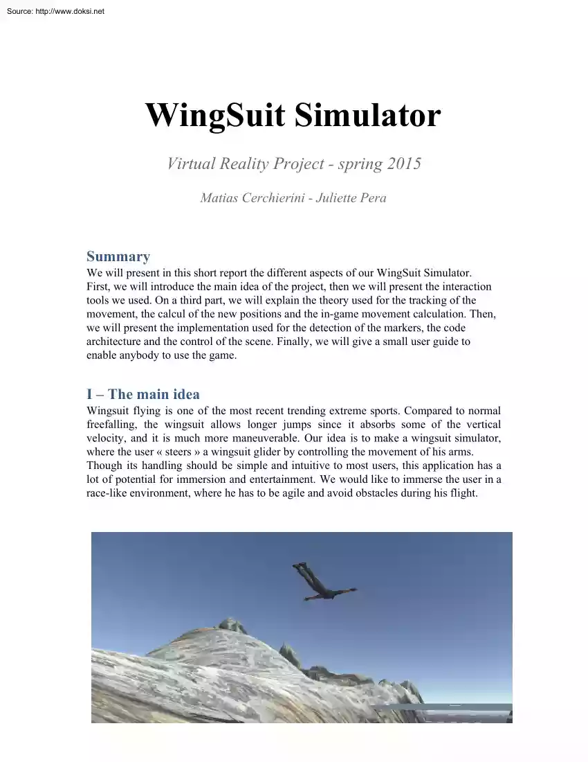
Source: http://www.doksinet WingSuit Simulator Virtual Reality Project spring 2015 Matias Cerchierini Juliette Pera Summary We will present in this short report the different aspects of our WingSuit Simulator. First, we will introduce the main idea of the project, then we will present the interaction tools we used. On a third part, we will explain the theory used for the tracking of the movement, the calcul of the new positions and the ingame movement calculation. Then, we will present the implementation used for the detection of the markers, the code architecture and the control of the scene. Finally, we will give a small user guide to enable anybody to use the game. I – The main idea Wingsuit flying is one of the most recent trending extreme sports. Compared to normal freefalling, the wingsuit allows longer jumps since it absorbs some of the vertical velocity, and it is much more maneuverable. Our idea is to make a wingsuit simulator, where the user « steers » a
wingsuit glider by controlling the movement of his arms. Though its handling should be simple and intuitive to most users, this application has a lot of potential for immersion and entertainment. We would like to immerse the user in a racelike environment, where he has to be agile and avoid obstacles during his flight. Source: http://www.doksinet II – Interaction tools There were several alternatives we considered for the interaction with the user. Obviously, we would ideally have used motion tracking tools like the Kinect or handheld devices like the Wiimote. Such a setup would have allowed good precision and an easy workload for the tracking code. However, both of us don’t own such tools and since we were working most of the time separately, it would have been difficult to borrow one and use it concurrently. Thus, we decided to go for a completely computervision based tracking. Thankfully, the setup is very simple: we only need to track movements on a 2dimensional basis
(the position of the head and the vertical opening of each arm), so we were confident that existing techniques would be perfectly fine using only the computer’s webcam, sending the tracking data using an UDP socket. III – Theory Movement tracking We will equip the user with a set of 3 markers: one for each hand and one for the head. Those markers will be detected on the frames recorded by the webcam. Calcul of new positions At each frame, we compute the angle each arm makes with the user’s body, and the head’s position. For each arm, we estimate its orientation by defining a segment between the arm marker and the head marker, and compute the angle this segment makes with the vertical axis. Thus, for example, if both arms are aligned with the horizontal axis (“wide” opened), the angle of each arm would be 90 degrees. An angle of (about) 0 degrees means the arm is aligned with the user’s body. Source: http://www.doksinet The head position is represented as a normalized
offset from the center of the frame, so that the coordinate (0,0) is the center of the frame, (1,1) is the bottomright corner, and (1, 1) the topleft corner. More formally, we will send ΔR, ΔL and ΔH=(ΔHx,ΔHy) to our 3D scene. Once we have the information of the arms angles and head position, we can modify the body position of the avatar consequently. Inside the game, we update the viewpoint of the camera according to the head position and the arm orientation according to the angles. Ingame movement calculations The last step consists on changing the velocity of the avatar accordingly to his arms positioning. Our goal is to mimic as much as possible the handling of a wingsuit in real life. Intuitively, we would like to represent the movement in the following way: Source: http://www.doksinet If both arms are wide opened at the same angle, the wingsuit absorbs the fall and the character travels horizontally If both arms are closed, the wingsuit isn’t
effective and the character falls vertically By opening one arm more than the other, the user is pushed sideways in the direction of the closed arm The computation is done in the following way: each wing of the character will contribute independently to the character’s velocity. We define the following values: L interp coeff , R interp coeff , that represent the percentage of the angle of the left and right arms. 10 means the arm is fully opened (estimated to be at 100 degrees), and 00 means the arm is close to the body (0 degrees). L vel contrib , R vel contrib , the vectors that represent the velocity induced by each wing. Suppose that the character moves forward along the X axis, and laterally along the Z axis. We define three constants that represent the speed induced in each axis by the wings: FORWARD PUSH (x axis), LATERAL PUSH (z axis), H EIGHT PUSH (y axis). Then, the velocity contributions are computed as follow: L vel contrib = (FORWARD
PUSH*L interp coeff, HEIGHT PUSH(L interp coeff 1.0), LATERAL PUSH*L interp coeff) R vel contrib = (FORWARD PUSH*R interp coeff, HEIGHT PUSH(R interp coeff 1.0), 1*LATERAL PUSHR interp coeff) Source: http://www.doksinet Then the character’s velocity is simply computed as L vel contrib + R vel contrib. Here are some explanations: the term HEIGHT PUSH*(interp coeff 1.0) will be equal to 0.0 when the corresponding arm is fully opened (interp coeff = 10), so that there is no vertical fall. Since interp coeff <= 10, this term will be negative otherwise and will define the vertical velocity when the character is falling. However, in the game, we noticed that the character starts falling as soon as we close the arms a little, which is not practical. So we decided to replace the 10 constant with 07 This means that the character starts falling only when both arms are opened at around 70 degrees, which allows more liberty of movement for the user. Because of that, the
vertical velocity could become positive when interp coeff > 0.7, so we need to “manually” force the vertical velocity to be at most 0.0 Case 1: Both arms opened L interp coeff = 1.0 and R interp coeff = 10 L vel contrib = (FORWARD PUSH, 0, LATERAL PUSH) R vel contrib = (FORWARD PUSH, 0, LATERAL PUSH) Case 2: Both arms closed L interp coeff = 0.0 and R interp coeff = 00 L vel contrib = (0, HEIGHT PUSH, 0) R vel contrib = (0, HEIGHT PUSH, 0) Source: http://www.doksinet III – Implementation Detection of the markers We have tested several different techniques for the detection. Unfortunately, there are always tradeoffs and we had to take some decisions. Here is a list of what we tried and why they were or weren’t suited. Classifierbased detection : OpenCV allows to use classifiers, which are patterns corresponding to some reallife objects. There are some free online classifiers for face and hands detection available, which would have been perfect as they are
very practical for the user (no fiducial marker to wear). However, it turned out that running even a single classifier (the face) was horribly slow using OpenCV, so we gave up on this idea. Skincolor detection : It is possible to “threshold” an image depending on the color. By using a skincolor as threshold, we obtain a white/black image showing the visible body parts. When we tried this, we found out it is difficult to deduce the position of the body parts since the visible size of each part varies a lot. It is also very sensitive to noise (wearing a white shirt, for example, would mess a lot with the detection). Templatebased detection : There are lots of examples online in OpenCV that show how to detect a particular symbol within another image. We tried using it by assigning a symbol for the head and each arm, and then tracking these markers independently. However, template detection requires that the symbol in the frame has the exact same size and rotation as
provided in the image (so it is not scale and rotation invariant). This means that multiple runs were necessary, which made the program far too slow. Circle detection (actually used technique) : From our experience with Templatebased detection, we deduced it would be best to use only circles as markers as they are rotation invariant. After some research, we found out OpenCV has a function called HoughCircles, which allows to detect all the visible circles within one image. It is very parameterizable, very fast, and can detect everything in one single run. The biggest problem with this technique is its sensitivity to noise: the background behind the user should be uniform, otherwise some circles might be wrongly detected. Nevertheless, this was the tracking method we eventually chose. Code architecture The code used for the tracking is relatively small. Here is an overview of the classes PoseTracker.cpp : contains the “main” function. Initially, it creates an instance of
CircleDetector and UDPSender, then starts the webcam. Then it continuously retrieves a Source: http://www.doksinet frame from the webcam, find the body pose using CircleDetector, and send the data on a socket using UDPSender. CircleDetector.cpp/h : the main functions are detectCircles and getMarkerData. This class keeps track of the three circles that identify the head and arms. When calling the function detectCircles (passing a webcam frame as parameter), this object detects all circles on the frame and will try to determine which circles correspond to a marker. We use the following estimation: the head marker should be located near the center of the frame, close to the top. The right arm should be on the left of the image, and viceversa for the left arm. For each detected circle, the function will evaluate which body part it is most probably associated to. Then, for each body part, we associate the circle with the highest probability. After that, the user calls the function
getMarkerData, which retrieves all information we need in our scene: head offset and angle of each arms with the vertical axis (in radians). UDPSender.cpp/h : upon instantiation, this class starts an UDP client socket to the provided port and IP address. By default, the IP is set to localhost The function sendData allows to transmit a packet containing the values needed in the 3D scene. Inside Unity, we only needed to make one script, M arkerDataListener . The script must be associated to the ingame character; in the editor, the user must define the left and right arm bones of the character to the script, as well as the instance of the main camera. This script will receive the UDP packets sent by the tracking part, and update the character accordingly. The scene we provide has all the setup already done Control of the scene We modeled a terrain representing a mountain environment. There is a valley that forms a path that the player must follow. Along the path, there are
beams obstructing the way, and some red spheres disposed in a couple places. The player must travel along the valley without touching the terrain or the beams, in which case the game is lost (the character stops moving). The character can run into the spheres, which throws them down the valley. This adds a little more fun, but also challenge since the spheres are placed in risky places. Source: http://www.doksinet IV – User guide Libraries and tools The 3D scene and physical interaction was modeled using Unity3D 5.01f (it won’t work under Unity 5.00!) Marker tracking was implemented using OpenCV 241 The terrain textures and character models were free assets available on the Unity asset store. The Unity scene is provided as a .unitypackage file You can import it under the Assets menu in the editor. Be sure to open the scene terrain sceneunity in order to display the level. On Windows: download OpenCV 2.41 from its official website Extract the content somewhere on the computer,
then add OpenCV’s Visual Studio 10 build in the system’s PATH variable: in our case, the path was opencv/build/x64/vc10/bin. Restart the computer. It is then possible to run the tracking program “detectionexe” In order to compile the program, best is to use V isual Studio . On Mac: compile the tracking program (you can use the following line: g ++ $(pkgconfig cflags libs opencv) UDPSender.cpp CircleDetectorcpp PoseTrackercpp o detection ) and launch the executable. Important note: some computers define differently the index of the webcam. If the program fails because it can’t find the camera, try running the program with the command “detection 1” instead. Usage Before starting, it is important to make sure that the user is not wearing clothes with a lot of patterns on it, and that the background is quite uniform or this could disturb the detection. The user must wear 3 markers that we will provide: on in each hands and on on the forehead.
However, it is really important to wear the in such a position that will allows the circle to be facing the camera or the detection will be lost. Before starting the game, make sure the user is at a good distance with the camera in order to stay in the field of view of the camera if he is extending his arms. Once all the above conditions are respected, the game can be started. First, launch the executable for the tracking. Then, open Unity3D, and load the scene terrain scene.unity When ready, press the “simulate” button inside Unity. Note that the executable can be started after Unity, the order doesn’t matter. The movement of the avatar will be controlled by the movement of the user’s arms and head: arms opened > forward movement, it models the glide. arms closed > vertical movement, it models the drop. Source: http://www.doksinet one arm opened / one arm closed > lateral movement in the direction of the closed arm. lateral or vertical
movement of the head > change the viewpoint of the scene accordingly. The user now has to avoid the obstacles or he will die. For more fun, he can try to push the red spheres. Note: by clicking on the character object in the editor (named “vincent”), you should find a “difficulty” parameter on the right panel, under the component MarkerDataListener. This floating value controls the speed of the character; 1.0 is a quite easy flow, 20 should pose a challenge. Simple marker setup: print 3 circles and tape them on the body as illustrated Conclusion To conclude, it was a very interesting project that taught us various techniques used in the development of virtual reality project. However, we encountered many difficulties. Without using any tracking hardware like Kinect, the interaction is made very difficult as we need real time performances. We had to try a lot of different techniques until we found a satisfying setup. Still, the detection of the marker is not very robust,
it implies to have a simple background with not a lot of details, colors or light. Also, the user has to wear markers, which may decrease the sense of presence and embodiment during the game. Finally, the discontinuity of the values sent to the scene make increases the latency and the risk of cyber sickness for the user. Nevertheless, we managed to create a properly usable application, which can be run with no other hardware than a regular laptop or home computer and some handmade markers