Datasheet
Year, pagecount:2016, 12 page(s)
Language:English
Downloads:3
Uploaded:October 11, 2018
Size:1 MB
Institution:
-
Comments:
Attachment:-
Download in PDF:Please log in!
Comments
No comments yet. You can be the first!


Content extract
Source: http://www.doksinet 14th International LS-DYNA Users Conference Session: Constitutive Modeling Experimental and Numerical Investigation of the Tearing Resistance of a Parachute Woven Fabric using LS-Dyna® B.Perin1, ChEspinosa2, RBlois1, PBordenave1, 1 2 DGA Aeronautical Systems, 47 rue Saint Jean, F-31131 Balma Cedex, France Université de Toulouse / Institut Supérieur de l’Aéronautique et de l’Espace, 10 av. E Belin, BP 54032, F-31055 Toulouse Cedex 4, France Abstract The performance of a parachute system is conditioned by its ability to sustain the loads applied by its environment during its life. Among others tear resistance is crucial since the unstable propagation of small defects into cracks can lead to the catastrophic loss of load carrying capacity. Defects under consideration are pre-existing notches or cuts. Experimental campaigns of quasi-static tear resistance in the warp and weft directions of parachute woven flexible fabrics have been realized at DGA
Aeronautical Systems following the normalized tests defined by NF G07145 and NF G 07-149 (‘trousers’ tear or Single Rip Method, and ‘nail’ tear, see Fig. 1) On the contrary to the case of a metallic material, which tear resistance can be related to notch resistance through the yield strength and local plasticity, tear resistance of a tissue involves complex stress and stain distributions in the yarns of the woven fabric. It is shown that sliding of the rip stop yarns are not well handled by the testing standards. A numerical simulation plan has been designed and operated in order to determine the characteristics of a representative numerical model for both the material behavior and the large flexible structure, in the perspective of including it in a full 3D FSI simulation. Results are presented and compared to experimental ones Using a homogenized anisotropic material, the size of the mesh and the contact algorithm are the critical parameters that handle the crack propagation
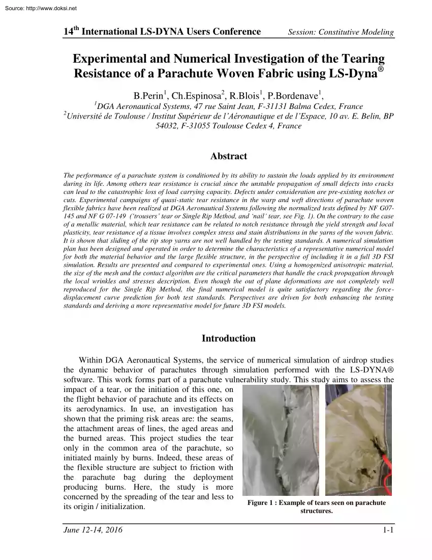
through the local wrinkles and stresses description. Even though the out of plane deformations are not completely well reproduced for the Single Rip Method, the final numerical model is quite satisfactory regarding the forcedisplacement curve prediction for both test standards. Perspectives are driven for both enhancing the testing standards and deriving a more representative model for future 3D FSI models. Introduction Within DGA Aeronautical Systems, the service of numerical simulation of airdrop studies the dynamic behavior of parachutes through simulation performed with the LS-DYNA® software. This work forms part of a parachute vulnerability study This study aims to assess the impact of a tear, or the initiation of this one, on the flight behavior of parachute and its effects on its aerodynamics. In use, an investigation has shown that the priming risk areas are: the seams, the attachment areas of lines, the aged areas and the burned areas. This project studies the tear only in
the common area of the parachute, so initiated mainly by burns. Indeed, these areas of the flexible structure are subject to friction with the parachute bag during the deployment producing burns. Here, the study is more concerned by the spreading of the tear and less to Figure 1 : Example of tears seen on parachute its origin / initialization. structures. June 12-14, 2016 1-1 Source: http://www.doksinet Session: Constitutive Modeling 14th International LS-DYNA Users Conference It is possible to define the tearing resistance of a woven fabric as the property owned by a fabric to withstand before breaking to a force which tends to separate the yarns of woven fabric by breaking some of these yarns. A woven fabric is a textile formed by the interweaving of yarn of warp and weft. This interweaving is performed during weaving on the loom. The warp refers to the parallel yarns to the forward direction of the fabric during manufacture. The weft is all perpendicular yarn to warp yarns,
called also picks. The slant direction is the direction oriented 45° to the warp Figure 2 : Representation of warp, slant and weft direction on fabric. direction. The contexture is the density of yarns in the fabric, and the armature is the interweaving mode of warp and weft yarns. To sum up, the tear is a complex phenomenon that takes into account the interaction between the warp and weft yarn thanks to sliding, reorientation, stacking, deformation and the breaking of some yarn. The study is mainly interested in four woven fabrics which composed two French military parachutes. They are constituted of yarn of the same material, but differ in weaving and coating added on. The main characteristics of them are indicated in the following figure: Armature mode Weaving feature Treatment Application of the coating Fabric 1 Ripstop 16-2 Taffeta 17th yarn doubled (warp and weft) Impermeable Hot rolling Composition Fabric 2 Leno fabric Permeable (hard) Fabric 3 Ripstop 15-2 Taffeta 16th
yarn doubled (warp and weft) Impermeable Fabric 4 Leno fabric Taffeta 15th and 16th yarn doubled (warp and weft) Permeable (weak) Junction of a coating of polymerized resin Polyamide yarn PA 6-6 High Tenacity View on microscope Thinkness Density mass 54 μm 777 kg/m3 192 μm 531 kg/m3 51 μm 794 kg/m3 67 μm 701 kg/m3 Figure 3 : Main characteristics of 4 fabrics used for French parachutes. The Ripstop technology allows avoiding or limiting the spreads of tears if primers occur. The aim of the present study is to evaluate the different ways offered by LS-DYNA software to represent both the material characteristics and the structural characteristics of the behavior during a tearing test. For that purpose, tests results are presented, and different options of LSDYNA are compared 1-2 June 12-14, 2016 Source: http://www.doksinet 14th International LS-DYNA Users Conference Session: Constitutive Modeling 1. Characterization of the textile tearing Before studying the textile
tearing, a mechanical characterization is performed. It is possible to draw diagrams of stress/displacement thanks to tensile tests, as for a metallic material. This allows calculating Young’s, Poisson’s and shear modulus. To determine the shear modulus, it is necessary also to perform a test on the slant direction, this means to cut the test piece with an angle 45° to warp direction. For Fabric#2, an example of tensile curves is illustrated on Fig 4 Figure 4 : Example of tensile curves for fabric The tensile curves on the warp and weft directions have six parts. The first part (1), for which the resistance force is null, matches to the adjustment for bringing a load on the fabric because the test is performed without initial tension. The part two (2) is the area where an interfiber friction occurs The third area (3) is due to the ripple transfer between fibers and the strain of the fibers’ section. Under the tensile stress, the fibers having a natural ripple caused by the
weaving tend to become straight in the direction of tension, this causes a change of the ripple. Moreover, this is accompanied by the elongation of fibers caused by the crushing of a fiber over another. The fourth part (4), linear, represents the behavior of tensile fibers, in other words, it is the extension of the yarn in the longitudinal direction of the test. The part five (5) corresponds to the plastic deformation of fibers constituting the longitudinal yarns followed by the latest part of the curve (6) which is the breaking of the fabric. This separation into different resistance regimes is done ‘by hand’, under the consideration of the slope evolution. , It can be seen that the strength in the warp direction is higher than in the weft direction but both force curves have the same shape and evolution versus displacement, in particular the double curvature in the irreversible regime. This is not at all the case for the slant direction During the tensile test on the slant
direction, another phenomenon occurs in addition to the transfer of ripple and allows a large initial movement with very little resistance force (1). It is the rotation mechanism of the fibers together, which corresponds to the disorientation of the weft and warp directions. The strength on the slant direction is much lower than in the fiber direction but the breaking elongation is approximately two times higher than in the warp and weft direction. We can see thanks to this fabric behavior that it is highly anisotropic and it is important to take account this characteristic in the numerical models. Mechanical characteristics extracted from the tests are summarized in Fig. 5: June 12-14, 2016 1-3 Source: http://www.doksinet Session: Constitutive Modeling Strength (Fr) Breaking elongation (εr) 14th International LS-DYNA Users Conference Fabric number Warp (daN/5cm) 1 45 2 130 3 40 4 40 Weft (daN/5cm) Warp (%) Weft (%) 38 20 30 125 n.c n.c 40 20 30 40 22 22 Figure 5:
Characteristics of fabrics DGA Aeronautical Systems has equipment and standardized methods for the characterization of textile elements. Thus, the tear tests were performed in conformity with [1] and [2]. Force sensor The test of nail tear is performed with a test sample of Mobile arm of the fabric of 300 mm x 50 mm. The tensile machine fabric sample is clamped into the upper jaw on a length of 10mm. The nail moves through the fabric and the strength is read at the upper Upper jaw (mobile) jaw. (Fig 6-left) The test of single rip method, also called trousers tear, is Test piece of fabric performed with a test sample of fabric of 200 mm x 50 mm already notched on a length of 100mm in Lower jaw (fix) the longitudinal direction. Each part is set in a jaw of the tensile Nail head machine and the crack is propagated in length direction (Fig. Figure 6 : Tensile machine DY-34 of DGA used for nail tear (left) and trousers tear (right) 6-right). The acquisition frequency of the strength and
the displacement for the two tests is 50Hz. An overview with microscope allows visualizing the state of a torn structure of Fabric 2 (Fig. 7a and 7b) and Fabric 3 (Fig 7c, 7d, 7e) During nail tear tests of the Fabric 2, packs three yarns are broken in the warp and weft direction (Fig. 7a) Furthermore, disorientation of cross yarns is small before break. For the trousers tear, the cross yarns slide relatively to the longitudinal yarns to reorient and then break. We see no yarns reorganization per pack of three contrary to the nail tear case (Fig 7b). However, the Ripstop yarns in the perpendicular direction to the tearing direction slide against the other yarns and are not broken. The yarns are gathering under the nail without breaking but rather by sliding from the structure. Fig 7c shows clearly the Ripstop yarns that are no longer present at the tear. 1-4 June 12-14, 2016 Source: http://www.doksinet 14th International LS-DYNA Users Conference Session: Constitutive Modeling The
Ripstop yarns allow decreasing the propagation of the tear. If they do not slide, peaks of break strength of these yarns should be greater than breaking other yarns. Due to this slide effect, the relevance of standardized tear tests to determine the real tearing force is questioned. Indeed, the tearing force value determined are not representative, especially as these Ripstop yarns should help to limit the propagation of tears. Thus, the study presented in this paper is about only the tear fabric without Ripstop, which means the Fabric 1 mainly. a b d c e Figure 7 : For Fabric 2, microscope view x1.25 of nail tear (a) and x10 view of trousers tear (b) both on warp direction. For Fabric 3, microscope view x125 of nail tear (c) on warp direction (Risptop yarns are snatched), and x2.0 view of trousers tear on weft direction for left side (d) and right side (e) of the piece of fabric 2. Numerical modeling of textile tearing a. Generality Modeling numerical model of the textile
tearing experiments has been done with the software LS-DYNA release R7.11 Revision 88541 on 04/04/2014 and R712 Revision 95028 on 07/01/2015. This software is used by the simulation service of DGA Aeronautical Systems, particularly to simulate the Fluid Structure Interaction between parachutes and their environment (air here). Different stress-strain material models are available in LS-DYNA for fabric modeling. A short review is proposed here relative to the advantages/limitations to represent our materials or other tissues. 34-Fabric 214-Dry Fabric 235-Micromechanics Dry Fabric Velocity of deformation effect Breaking Anisotropic Damaging X X X X X X Tension/compression Differently treated X X X Figure 8 : Table of options of textile material models. The 214-Dry Fabric material does not consider Poisson’s effects. It is very suitable for bulletproof vest modeling. This material model seems very attractive because it takes into account strain rate effects and failures. It
also allows continuous damage The 235-Micromechanics Dry Fabric material was developed to model inflatable structures, parachutes, bulletproof vests and airbags. This model does not distinguish between warp and weft direction but considers the fibers angle of rotation. This model is attractive since it represents a way to take into account the microstructure of the tissue which is crucial for the June 12-14, 2016 1-5 Source: http://www.doksinet 14th International LS-DYNA Users Conference Session: Constitutive Modeling strength of the structure. The setting difficulty of this model is the knowledge of all the mechanical characteristics of the yarn constituting the fabric and also the weaving geometry. The 34-Fabric material has been especially developed for the modeling of car airbags. By opportunity, it is used on all parachute models at DGA Aeronautical Systems. The simplest model is to setting the Young modulus in both directions (warp and weft), the Poisson’s ratio and the
shear modulus. The material then assumes a linear stress-strain behavior It is also possible to input the stress-strain law from tensile tests (using the formulation 4, 14 or -14) and to use fully integrated shell elements (formulation 16). This material was chosen for this study with the formulation 14 as it allows for large deformation and noFabric 1 Fabric 2 orthogonal angles weaving. Ewarp 496 MPa 434 MPa The material characteristics have been determined Eweft 282 MPa 420,5 MPa through experimental tests. The Fabric#34 material makes E45° 523 MPa 296,1 MPa assumption of a linear anisotropic behavior law. Poisson’s ratios have also been obtained from tensile test but the values ν12 0,3 0,3 are not correct although of the values are very similar to what ν21 0,3 0,3 can be found in the literature [3]. G12 266 MPa 97,7 MPa The use of AOPT = 0.0 allows to the material to stay Figure 9 : Table of main oriented relative to the local reference of the shell element. characteristics for
fabric 1 and 2 *Mat Fabric can only be used with a shell section. For this problem, the shell formulations 9 (Belytschko-Tsay membrane), 16 (Belytschko-Tsay shells) and 10 (Belytschko – Leviathan and Wong-Chiang) were tested. The formulation 9 by calculating only membrane does not represent well the shell deformations when the fabric is subjected to the off plane shear. The formulation 16 is fully integrated considering all stresses but requires the longer calculation time. The formulation 10 is a good compromise between time calculation and representation of the tissues deformation. b. Modeling tear through element erosion There are different possibilities to create the tear in LS-DYNA. Here, the method by element erosion that offers LS-DYNA with *MAT ADD EROSION was used and give the most conclusive results that are presented here. Modeling of nail tear The nail tear is modeled with a sample of fabric (here fabric 2) of 97,5mm length in contrary to the 250mm length of the real
test in the aim to limit the computational time. The model is composed of a rigid cylinder representing the nail and of the sample of fabric (Fig. 7) The chosen mesh size of the fabric for this model is a square of 0,5mm x 0,5mm side. The fabric is composed by 19436 meshes and the nail by 6000 solid elements. 1-6 Figure 10 : Structure at initial state and beginning of the tear . June 12-14, 2016 Source: http://www.doksinet 14th International LS-DYNA Users Conference Session: Constitutive Modeling The nodes of the upper line of the sample are clamped. The nail is moving down, at the velocity of 10m/s. This velocity is one hundred times that for the real test to reduce the computational time. Induced oscillations in the fabric are then filtered using the *DAMPING PART MASS option. Moreover, this damping allows avoiding vibrational modes when breaking element. To avoid the interpenetration of the fabric with itself when it folds, an auto-contact was set through *CONTACT AIRBAG
SINGLE SURFACE ID with penalty coefficient at 2 (SFS). Many types of contact between the nail and the fabric were tested. The only leading to acceptable results are: - *CONTACT SURFACE TO SURFACE: method of contact detection based on nodes (old algorithm of LSDyna) and application of the loads by the penalty method. This method involves repulsing the nodes entering in the contact surface by applying a spring forces. - *CONTACT CONSTRAINT SURFACE TO SURFA CE: method of contact detection based on segments with the creation of a bucket around the segment (new algorithms of LS-Dyna) and loads application by constrains method. Figure 11 : Contact by penalty method (up) and by constraint method (down) The penalty method does not properly manage the contact between the nail and the fabric despite a high value of penalty coefficient and whatever the mesh size of the nail (Fig 11). The constraint method is more efficient because there is no penetration of the fabric by the nail (Fig 11).
The gap between the mesh of the nail and the fabric is due to the consideration of the shell thickness in the contact. The difficulty of the implementation of this contact is from geometry Indeed, there is a contact between a shell edge and a rigid element. This is why « Automatic » contacts do not work. To create erosion of elements with the fabric material, we have used the additional card *MAT ADD EROSION. This allows setting a number of criteria in order to erode an element, that is to say removing of the model. In our case, only the deviatoric part of the stress tensor is considered because there is no yield strength due to the hydrostatic pressure (incompressible hypothesis). Values of Von Mises stresses determined by tests-calculation comparison where used. Computation times are about 2h to 3h. Finally, on the following figure are represented the measured results of force-displacement curves, and comparisons between visual observations and numerical simulations of the coupon
deformation. June 12-14, 2016 1-7 Source: http://www.doksinet Session: Constitutive Modeling 14th International LS-DYNA Users Conference Nail displacement (mm) Figure 12 : Simulation and test comparison: Diagram of Force/Displacement of nail tear for fabric 2 (a) View of the simulation model and test set for the nail tear (b) The force-displacement curve can be decomposed into two phases. The first one (1) corresponds to the initial distortion of the fabric and also of the sliding of yarns onto each other. The observed difference for the part (1) is due to two reasons: First, the fact to have created the initiation Figure 13 : Without (a) and with (b) initial tear. by piercing the fabric with the nail in the experimental test has weakened the yarns around the nail which produces early breaks in the tear test (67 N). Second, it is due to the sliding of the perpendicular yarns to the tear direction relatively to the other yarns. This is not considered in the numerical model To
highlight the effect of the tear initiation, it is possible to set up a similar simulation with one finite element removed to initiate the tear. This improves slightly the convergence test / simulation curves The second part (2) of the curves is in the contrary very similar between the test curve and this one from numerical simulation. The mean force of the tear from modeling is 143 Newton, which is very close to the mean force from test of 142,6 Newton. Oscillations are also very similar The visual result is in line with the expectations, both in the folds and in the global shape of the torn fabric. To analyze the kinematics and the distortion of the fabric, there is difficulty to show the velocity vectors because it is a 3D problem with high distortions in the 3 directions and with many folds and wrinkles. However, it is possible to show the displacement of the nodes at the beginning and at the middle of the tear, Fig. 14 The observed deformations are coherent with reality and there
is no discontinuity between several meshes Figure 14 : Node displacement following X, Y and Z at the side by side. beginning of the tear (up) and at the middle of the tear (down) 1-8 June 12-14, 2016 Source: http://www.doksinet 14th International LS-DYNA Users Conference Session: Constitutive Modeling Modeling of the Single Rip Method This test was modeled with a sizing piece of fabric of 150mm x 50mm split of a 50mm length. The embedded part of fabric is not represented Many forms of initial geometries were tried in the aim of representing the reality the most faithfully (Fig. 15) z x y 50 mm 100 mm a b c Figure 15 : Initial (a) and final (b) configuration of the numerical model and test view (c) of trousers tear. An initial geometry was firstly made thanks to a purely geometric drawing. Then, we got the numeric final shape by subjecting it to a volume force 100 times greater than its weight with a rigid square representing the lower jaw of the machine. Moreover, to
avoid the mesh deformations of the sample in this pre-computation, the elasticity moduli were increased to a value of about 1 MPa. The lower nodes of the sample are clamped; the upper nodes have an imposed velocity upwards. The translation velocity of these nodes is 100 mm/s, like the real test, but it was still necessary to add damping to prevent oscillations of the break. The size of the meshing is around 5000 square shells. The smallest meshes have a length of 1.2mm The computation is done in 2 hours on 3 processors Fig. 16 shows the global deformation of the fabric sample between the numerical model and the real test for a torn length of 45mm. This indicates as well that the numerical simulation of the torn is very close to that observed in test. a b Upper jaw displacement (mm) Figure 16 : Simulation and test comparison: diagram of Force/Displacement of trousers tear for fabric 2 (a) View of the simulation model and test set for the trousers tear at 52 mm (b) June 12-14, 2016
1-9 Source: http://www.doksinet Session: Constitutive Modeling 14th International LS-DYNA Users Conference Diagram on Fig. 16a gives the superposition of the tear curve extracted from experimental test and from numerical simulation. As in the case of Central nail tear, the curves are composed by two parts and are Node highly similar. It is also possible to improve the numerical representation of the initial priming of the test by adding a central node and no longer an element (Fig. 17) The average force of the tear extracted from the Figure 17 : Without and with initial tear. simulation is 59 Newton; the read average force of the test is about 62 Newton, which less than 5% error. Fig. 16b gives a global view of a test and a simulation result We can see many similarities between the two results but one aspect is perfectible. In fact, we can clearly see that the out of plane deformations are not completely well reproduced. Figure 18 : Node displacement followings X, Y and Z at 52mm
torn As shown in Fig. 14, Fig 18 shows the nodal displacement on the Fabric 2, here at 52 mm torn, to provide an overview of the good behavior of the model. Discussion Different possibilities to simulate tear in LS-DYNA that have been tested during this project are: The nodes failure (*CONSTRAINED TIED NODES FAILURE with criteria of maximal plastic strain); Extended finite elements (X-FEM) allowing the failure of a finite element; Without meshing Smoothed Particle Hydrodynamics (SPH) ; method Element-free Galerkin (EFG) ; Erosion of elements (*MAT ADD EROSION). The LS-DYNA software offers an easy method to create the nodes failure through the card *CONSTRAINED TIED NODES FAILURE which allows Contact breaking the link between two, three or four nodes using a nodes maximal plastic strain criteria. Even though our material has area experienced irreversible behavior in real tests, choosing the Fabric#34 material for modeling was the best comprise regarding the
structural behavior. As a consequence, it was not Figure 19 : Nodes failure model 1-10 June 12-14, 2016 Source: http://www.doksinet 14th International LS-DYNA Users Conference Session: Constitutive Modeling possible to use a criteria based on the plastic strain because this material only consider an elastic behavior. The second method involves to use the card *CONTACT TIEBREAK NODES ONLY allowing to create breaking between a node and a part (i.e the sample of Fabric) This method of setting is longer than the use of erosion and only proposes one break criteria. Furthermore, this method was developed to set contacts in LS-DYNA and not for use in break mechanics. The EFG method (Element Free Galerkin) is a simulation method without meshing toward to the mechanical problems and allows the breaking. It can be based on shells (in contrary to SPH - Smoothed Particle Hydrodynamics) or solid elements. The advantage to be based on shells is to continue to use the same material of LS-DYNA
(Fabric). Methods without meshing which includes EFG are based on the subdivision of the structure by nodes. Each node has two functions defined on a small domain, called influence domain. These two functions are the weight function and the shape function. The advantage of EFG in relative to others methods without meshing is that allow to consider the breaking on a serious manner because the influence domain of a particle on one side of the breaking cannot go on the other side. Moreover, the Figure 20 : Fabric deformation particle on a side cannot interact with the ones on the other side. To thanks to EFG (gap of 0,25mm develop a model based on the EFG, a bibliographic review has shown between elements). Overview that few references are available. The documents on which it is (up) zoom (down) possible to refer are listed on [4], [5], [6] and [7]. The developed models have failed to simulate tear or only worked for small deformations. A representation of the nail displacement of 2,5mm
is presented on Fig 20. However, a very small initial meshing is required for the EFG method to work. It is possible that with an initial size of mesh lower than 0,25mm the model could better work but the computation time is already very long here. In this meshing case, the required time to reach 0.3mm of displacement of the nail was around 17 hours on 1 processor. The method using XFEM elements, i.e extended finite elements, allows modeling the propagation of the crack without the constraint that this crack follows the meshing. This method is based on the introduction of a function allowing to better take into account singularities as cracks without introduce problem on solving equations at the boundary conditions. The crack is spread when the COD (Crack Opening distance) is reached. To use the extended finite elements with LS-DYNA, it is necessary to add a card in the shell section and to use the shell formulation 54 (shell XFEM). In this additional card, it also necessary to use a
cohesive material (only *MAT COHESIVE TH is available), the type of integration domain and the break criteria. Unfortunately the found bibliographic references [4][3], [8] and [9], it was not possible to run models with the extended finite element. Finally, the method used to model the tear convincingly with LS-DYNA was the method of erosion element with the card * MAT ADD EROSION. This one achieved whole of wished study cases with conclusive results and using a reasonable computational time. In terms of representativeness, some points remain to improve as the get final global shape of the Single Rip Method or also the Figure 21 : numeric model (a) and view of the beginning phase of a tear. Moreover, due to test (b) of nail tear on Ripstop fabric. June 12-14, 2016 1-11 Source: http://www.doksinet Session: Constitutive Modeling 14th International LS-DYNA Users Conference the validity problem of the fabric characterization having Ripstop yarns, it was not possible to get numerical
results for Fabric 1 and 3. This suggests to review the test method of these kinds of Fabric which yarns slip during the two types of test (nail and trousers). As shown of figure 21, the trend of the behavior is quite well reproduced, but not the specific behavior of the Rip Stop sliding. Conclusions Different possibilities to simulate tear in LS-DYNA have been evaluated in this project. Two criteria were used to compare numerical simulations and real tests, the force-displacement curve and the deformation of the tissue. The force-displacement curves are reproduced for the regular tissues. It was necessary to find a compromise between in plane behavior and the out of plane behavior in order to represent both the wrinkles and the successive breakage during tearing. The size of the elements was adjusted as the key parameter to reproduce the amount of resistance and the erosion technique was enough to represent the ruptures. But a problem still persists in representing the Rip Stop
behavior and in general the anisotropic and relative position of the yarns during the process. Tests are not representative, and it is not possible to simulate this phenomenon with a homogenized material model without any geometrical structural details taken into account. Future works will be focused on these two aspects References [1] [2] [3] [4] [5] [6] [7] [8] [9] French certified norm. Textiles, fabric tests, nail tear NF G07-145, December 1981 French certified norm. Textiles, fabric tests, Rip Single Method NF G 07-149, December 1981 Triboulet, P. « Notions de bases sur les plans d’expériences », Chalon sur Saône, France, September 2008 Guo, Y. and Al, “EFG and XFEM Cohesive Fracture Analysis, Methods in LS-DYNA”, LS-Dyna Seminar, Stuttgart, Germany, November 2010. Lu, H. S and Al, “Simulation of Reinforced Concrete Structure under Impact Loading using Meshfree Cohesive Failure Approach” 12th international users conference of LS-DYNA, October 2012. Kambur, C.,
“Assessment of mesh-free Methods in LS-DYNA: Modeling of Barriers in Crash Simulation”, Thesis, Stuttgart, Germany, May 2004. Majerus, J. and Al, « Element-Free Galerkin Method », Project Presentation, Liège university, Belgium, March 2010. Usman, A., “Numerical Modeling of Failure in Magnesium Alloys under Axial Compression and Bending for Crashworthiness Applications” Thesis, Waterloo university, Ontario, Canada, 2012. Villanueva, C-H and Al., “A complete methodology for the implementation of XFEM inclusive models”, University of Colorado Boulder, Department of Mechanical Engineering, May 2013. 1-12 June 12-14, 2016
Aeronautical Systems following the normalized tests defined by NF G07145 and NF G 07-149 (‘trousers’ tear or Single Rip Method, and ‘nail’ tear, see Fig. 1) On the contrary to the case of a metallic material, which tear resistance can be related to notch resistance through the yield strength and local plasticity, tear resistance of a tissue involves complex stress and stain distributions in the yarns of the woven fabric. It is shown that sliding of the rip stop yarns are not well handled by the testing standards. A numerical simulation plan has been designed and operated in order to determine the characteristics of a representative numerical model for both the material behavior and the large flexible structure, in the perspective of including it in a full 3D FSI simulation. Results are presented and compared to experimental ones Using a homogenized anisotropic material, the size of the mesh and the contact algorithm are the critical parameters that handle the crack propagation
through the local wrinkles and stresses description. Even though the out of plane deformations are not completely well reproduced for the Single Rip Method, the final numerical model is quite satisfactory regarding the forcedisplacement curve prediction for both test standards. Perspectives are driven for both enhancing the testing standards and deriving a more representative model for future 3D FSI models. Introduction Within DGA Aeronautical Systems, the service of numerical simulation of airdrop studies the dynamic behavior of parachutes through simulation performed with the LS-DYNA® software. This work forms part of a parachute vulnerability study This study aims to assess the impact of a tear, or the initiation of this one, on the flight behavior of parachute and its effects on its aerodynamics. In use, an investigation has shown that the priming risk areas are: the seams, the attachment areas of lines, the aged areas and the burned areas. This project studies the tear only in
the common area of the parachute, so initiated mainly by burns. Indeed, these areas of the flexible structure are subject to friction with the parachute bag during the deployment producing burns. Here, the study is more concerned by the spreading of the tear and less to Figure 1 : Example of tears seen on parachute its origin / initialization. structures. June 12-14, 2016 1-1 Source: http://www.doksinet Session: Constitutive Modeling 14th International LS-DYNA Users Conference It is possible to define the tearing resistance of a woven fabric as the property owned by a fabric to withstand before breaking to a force which tends to separate the yarns of woven fabric by breaking some of these yarns. A woven fabric is a textile formed by the interweaving of yarn of warp and weft. This interweaving is performed during weaving on the loom. The warp refers to the parallel yarns to the forward direction of the fabric during manufacture. The weft is all perpendicular yarn to warp yarns,
called also picks. The slant direction is the direction oriented 45° to the warp Figure 2 : Representation of warp, slant and weft direction on fabric. direction. The contexture is the density of yarns in the fabric, and the armature is the interweaving mode of warp and weft yarns. To sum up, the tear is a complex phenomenon that takes into account the interaction between the warp and weft yarn thanks to sliding, reorientation, stacking, deformation and the breaking of some yarn. The study is mainly interested in four woven fabrics which composed two French military parachutes. They are constituted of yarn of the same material, but differ in weaving and coating added on. The main characteristics of them are indicated in the following figure: Armature mode Weaving feature Treatment Application of the coating Fabric 1 Ripstop 16-2 Taffeta 17th yarn doubled (warp and weft) Impermeable Hot rolling Composition Fabric 2 Leno fabric Permeable (hard) Fabric 3 Ripstop 15-2 Taffeta 16th
yarn doubled (warp and weft) Impermeable Fabric 4 Leno fabric Taffeta 15th and 16th yarn doubled (warp and weft) Permeable (weak) Junction of a coating of polymerized resin Polyamide yarn PA 6-6 High Tenacity View on microscope Thinkness Density mass 54 μm 777 kg/m3 192 μm 531 kg/m3 51 μm 794 kg/m3 67 μm 701 kg/m3 Figure 3 : Main characteristics of 4 fabrics used for French parachutes. The Ripstop technology allows avoiding or limiting the spreads of tears if primers occur. The aim of the present study is to evaluate the different ways offered by LS-DYNA software to represent both the material characteristics and the structural characteristics of the behavior during a tearing test. For that purpose, tests results are presented, and different options of LSDYNA are compared 1-2 June 12-14, 2016 Source: http://www.doksinet 14th International LS-DYNA Users Conference Session: Constitutive Modeling 1. Characterization of the textile tearing Before studying the textile
tearing, a mechanical characterization is performed. It is possible to draw diagrams of stress/displacement thanks to tensile tests, as for a metallic material. This allows calculating Young’s, Poisson’s and shear modulus. To determine the shear modulus, it is necessary also to perform a test on the slant direction, this means to cut the test piece with an angle 45° to warp direction. For Fabric#2, an example of tensile curves is illustrated on Fig 4 Figure 4 : Example of tensile curves for fabric The tensile curves on the warp and weft directions have six parts. The first part (1), for which the resistance force is null, matches to the adjustment for bringing a load on the fabric because the test is performed without initial tension. The part two (2) is the area where an interfiber friction occurs The third area (3) is due to the ripple transfer between fibers and the strain of the fibers’ section. Under the tensile stress, the fibers having a natural ripple caused by the
weaving tend to become straight in the direction of tension, this causes a change of the ripple. Moreover, this is accompanied by the elongation of fibers caused by the crushing of a fiber over another. The fourth part (4), linear, represents the behavior of tensile fibers, in other words, it is the extension of the yarn in the longitudinal direction of the test. The part five (5) corresponds to the plastic deformation of fibers constituting the longitudinal yarns followed by the latest part of the curve (6) which is the breaking of the fabric. This separation into different resistance regimes is done ‘by hand’, under the consideration of the slope evolution. , It can be seen that the strength in the warp direction is higher than in the weft direction but both force curves have the same shape and evolution versus displacement, in particular the double curvature in the irreversible regime. This is not at all the case for the slant direction During the tensile test on the slant
direction, another phenomenon occurs in addition to the transfer of ripple and allows a large initial movement with very little resistance force (1). It is the rotation mechanism of the fibers together, which corresponds to the disorientation of the weft and warp directions. The strength on the slant direction is much lower than in the fiber direction but the breaking elongation is approximately two times higher than in the warp and weft direction. We can see thanks to this fabric behavior that it is highly anisotropic and it is important to take account this characteristic in the numerical models. Mechanical characteristics extracted from the tests are summarized in Fig. 5: June 12-14, 2016 1-3 Source: http://www.doksinet Session: Constitutive Modeling Strength (Fr) Breaking elongation (εr) 14th International LS-DYNA Users Conference Fabric number Warp (daN/5cm) 1 45 2 130 3 40 4 40 Weft (daN/5cm) Warp (%) Weft (%) 38 20 30 125 n.c n.c 40 20 30 40 22 22 Figure 5:
Characteristics of fabrics DGA Aeronautical Systems has equipment and standardized methods for the characterization of textile elements. Thus, the tear tests were performed in conformity with [1] and [2]. Force sensor The test of nail tear is performed with a test sample of Mobile arm of the fabric of 300 mm x 50 mm. The tensile machine fabric sample is clamped into the upper jaw on a length of 10mm. The nail moves through the fabric and the strength is read at the upper Upper jaw (mobile) jaw. (Fig 6-left) The test of single rip method, also called trousers tear, is Test piece of fabric performed with a test sample of fabric of 200 mm x 50 mm already notched on a length of 100mm in Lower jaw (fix) the longitudinal direction. Each part is set in a jaw of the tensile Nail head machine and the crack is propagated in length direction (Fig. Figure 6 : Tensile machine DY-34 of DGA used for nail tear (left) and trousers tear (right) 6-right). The acquisition frequency of the strength and
the displacement for the two tests is 50Hz. An overview with microscope allows visualizing the state of a torn structure of Fabric 2 (Fig. 7a and 7b) and Fabric 3 (Fig 7c, 7d, 7e) During nail tear tests of the Fabric 2, packs three yarns are broken in the warp and weft direction (Fig. 7a) Furthermore, disorientation of cross yarns is small before break. For the trousers tear, the cross yarns slide relatively to the longitudinal yarns to reorient and then break. We see no yarns reorganization per pack of three contrary to the nail tear case (Fig 7b). However, the Ripstop yarns in the perpendicular direction to the tearing direction slide against the other yarns and are not broken. The yarns are gathering under the nail without breaking but rather by sliding from the structure. Fig 7c shows clearly the Ripstop yarns that are no longer present at the tear. 1-4 June 12-14, 2016 Source: http://www.doksinet 14th International LS-DYNA Users Conference Session: Constitutive Modeling The
Ripstop yarns allow decreasing the propagation of the tear. If they do not slide, peaks of break strength of these yarns should be greater than breaking other yarns. Due to this slide effect, the relevance of standardized tear tests to determine the real tearing force is questioned. Indeed, the tearing force value determined are not representative, especially as these Ripstop yarns should help to limit the propagation of tears. Thus, the study presented in this paper is about only the tear fabric without Ripstop, which means the Fabric 1 mainly. a b d c e Figure 7 : For Fabric 2, microscope view x1.25 of nail tear (a) and x10 view of trousers tear (b) both on warp direction. For Fabric 3, microscope view x125 of nail tear (c) on warp direction (Risptop yarns are snatched), and x2.0 view of trousers tear on weft direction for left side (d) and right side (e) of the piece of fabric 2. Numerical modeling of textile tearing a. Generality Modeling numerical model of the textile
tearing experiments has been done with the software LS-DYNA release R7.11 Revision 88541 on 04/04/2014 and R712 Revision 95028 on 07/01/2015. This software is used by the simulation service of DGA Aeronautical Systems, particularly to simulate the Fluid Structure Interaction between parachutes and their environment (air here). Different stress-strain material models are available in LS-DYNA for fabric modeling. A short review is proposed here relative to the advantages/limitations to represent our materials or other tissues. 34-Fabric 214-Dry Fabric 235-Micromechanics Dry Fabric Velocity of deformation effect Breaking Anisotropic Damaging X X X X X X Tension/compression Differently treated X X X Figure 8 : Table of options of textile material models. The 214-Dry Fabric material does not consider Poisson’s effects. It is very suitable for bulletproof vest modeling. This material model seems very attractive because it takes into account strain rate effects and failures. It
also allows continuous damage The 235-Micromechanics Dry Fabric material was developed to model inflatable structures, parachutes, bulletproof vests and airbags. This model does not distinguish between warp and weft direction but considers the fibers angle of rotation. This model is attractive since it represents a way to take into account the microstructure of the tissue which is crucial for the June 12-14, 2016 1-5 Source: http://www.doksinet 14th International LS-DYNA Users Conference Session: Constitutive Modeling strength of the structure. The setting difficulty of this model is the knowledge of all the mechanical characteristics of the yarn constituting the fabric and also the weaving geometry. The 34-Fabric material has been especially developed for the modeling of car airbags. By opportunity, it is used on all parachute models at DGA Aeronautical Systems. The simplest model is to setting the Young modulus in both directions (warp and weft), the Poisson’s ratio and the
shear modulus. The material then assumes a linear stress-strain behavior It is also possible to input the stress-strain law from tensile tests (using the formulation 4, 14 or -14) and to use fully integrated shell elements (formulation 16). This material was chosen for this study with the formulation 14 as it allows for large deformation and noFabric 1 Fabric 2 orthogonal angles weaving. Ewarp 496 MPa 434 MPa The material characteristics have been determined Eweft 282 MPa 420,5 MPa through experimental tests. The Fabric#34 material makes E45° 523 MPa 296,1 MPa assumption of a linear anisotropic behavior law. Poisson’s ratios have also been obtained from tensile test but the values ν12 0,3 0,3 are not correct although of the values are very similar to what ν21 0,3 0,3 can be found in the literature [3]. G12 266 MPa 97,7 MPa The use of AOPT = 0.0 allows to the material to stay Figure 9 : Table of main oriented relative to the local reference of the shell element. characteristics for
fabric 1 and 2 *Mat Fabric can only be used with a shell section. For this problem, the shell formulations 9 (Belytschko-Tsay membrane), 16 (Belytschko-Tsay shells) and 10 (Belytschko – Leviathan and Wong-Chiang) were tested. The formulation 9 by calculating only membrane does not represent well the shell deformations when the fabric is subjected to the off plane shear. The formulation 16 is fully integrated considering all stresses but requires the longer calculation time. The formulation 10 is a good compromise between time calculation and representation of the tissues deformation. b. Modeling tear through element erosion There are different possibilities to create the tear in LS-DYNA. Here, the method by element erosion that offers LS-DYNA with *MAT ADD EROSION was used and give the most conclusive results that are presented here. Modeling of nail tear The nail tear is modeled with a sample of fabric (here fabric 2) of 97,5mm length in contrary to the 250mm length of the real
test in the aim to limit the computational time. The model is composed of a rigid cylinder representing the nail and of the sample of fabric (Fig. 7) The chosen mesh size of the fabric for this model is a square of 0,5mm x 0,5mm side. The fabric is composed by 19436 meshes and the nail by 6000 solid elements. 1-6 Figure 10 : Structure at initial state and beginning of the tear . June 12-14, 2016 Source: http://www.doksinet 14th International LS-DYNA Users Conference Session: Constitutive Modeling The nodes of the upper line of the sample are clamped. The nail is moving down, at the velocity of 10m/s. This velocity is one hundred times that for the real test to reduce the computational time. Induced oscillations in the fabric are then filtered using the *DAMPING PART MASS option. Moreover, this damping allows avoiding vibrational modes when breaking element. To avoid the interpenetration of the fabric with itself when it folds, an auto-contact was set through *CONTACT AIRBAG
SINGLE SURFACE ID with penalty coefficient at 2 (SFS). Many types of contact between the nail and the fabric were tested. The only leading to acceptable results are: - *CONTACT SURFACE TO SURFACE: method of contact detection based on nodes (old algorithm of LSDyna) and application of the loads by the penalty method. This method involves repulsing the nodes entering in the contact surface by applying a spring forces. - *CONTACT CONSTRAINT SURFACE TO SURFA CE: method of contact detection based on segments with the creation of a bucket around the segment (new algorithms of LS-Dyna) and loads application by constrains method. Figure 11 : Contact by penalty method (up) and by constraint method (down) The penalty method does not properly manage the contact between the nail and the fabric despite a high value of penalty coefficient and whatever the mesh size of the nail (Fig 11). The constraint method is more efficient because there is no penetration of the fabric by the nail (Fig 11).
The gap between the mesh of the nail and the fabric is due to the consideration of the shell thickness in the contact. The difficulty of the implementation of this contact is from geometry Indeed, there is a contact between a shell edge and a rigid element. This is why « Automatic » contacts do not work. To create erosion of elements with the fabric material, we have used the additional card *MAT ADD EROSION. This allows setting a number of criteria in order to erode an element, that is to say removing of the model. In our case, only the deviatoric part of the stress tensor is considered because there is no yield strength due to the hydrostatic pressure (incompressible hypothesis). Values of Von Mises stresses determined by tests-calculation comparison where used. Computation times are about 2h to 3h. Finally, on the following figure are represented the measured results of force-displacement curves, and comparisons between visual observations and numerical simulations of the coupon
deformation. June 12-14, 2016 1-7 Source: http://www.doksinet Session: Constitutive Modeling 14th International LS-DYNA Users Conference Nail displacement (mm) Figure 12 : Simulation and test comparison: Diagram of Force/Displacement of nail tear for fabric 2 (a) View of the simulation model and test set for the nail tear (b) The force-displacement curve can be decomposed into two phases. The first one (1) corresponds to the initial distortion of the fabric and also of the sliding of yarns onto each other. The observed difference for the part (1) is due to two reasons: First, the fact to have created the initiation Figure 13 : Without (a) and with (b) initial tear. by piercing the fabric with the nail in the experimental test has weakened the yarns around the nail which produces early breaks in the tear test (67 N). Second, it is due to the sliding of the perpendicular yarns to the tear direction relatively to the other yarns. This is not considered in the numerical model To
highlight the effect of the tear initiation, it is possible to set up a similar simulation with one finite element removed to initiate the tear. This improves slightly the convergence test / simulation curves The second part (2) of the curves is in the contrary very similar between the test curve and this one from numerical simulation. The mean force of the tear from modeling is 143 Newton, which is very close to the mean force from test of 142,6 Newton. Oscillations are also very similar The visual result is in line with the expectations, both in the folds and in the global shape of the torn fabric. To analyze the kinematics and the distortion of the fabric, there is difficulty to show the velocity vectors because it is a 3D problem with high distortions in the 3 directions and with many folds and wrinkles. However, it is possible to show the displacement of the nodes at the beginning and at the middle of the tear, Fig. 14 The observed deformations are coherent with reality and there
is no discontinuity between several meshes Figure 14 : Node displacement following X, Y and Z at the side by side. beginning of the tear (up) and at the middle of the tear (down) 1-8 June 12-14, 2016 Source: http://www.doksinet 14th International LS-DYNA Users Conference Session: Constitutive Modeling Modeling of the Single Rip Method This test was modeled with a sizing piece of fabric of 150mm x 50mm split of a 50mm length. The embedded part of fabric is not represented Many forms of initial geometries were tried in the aim of representing the reality the most faithfully (Fig. 15) z x y 50 mm 100 mm a b c Figure 15 : Initial (a) and final (b) configuration of the numerical model and test view (c) of trousers tear. An initial geometry was firstly made thanks to a purely geometric drawing. Then, we got the numeric final shape by subjecting it to a volume force 100 times greater than its weight with a rigid square representing the lower jaw of the machine. Moreover, to
avoid the mesh deformations of the sample in this pre-computation, the elasticity moduli were increased to a value of about 1 MPa. The lower nodes of the sample are clamped; the upper nodes have an imposed velocity upwards. The translation velocity of these nodes is 100 mm/s, like the real test, but it was still necessary to add damping to prevent oscillations of the break. The size of the meshing is around 5000 square shells. The smallest meshes have a length of 1.2mm The computation is done in 2 hours on 3 processors Fig. 16 shows the global deformation of the fabric sample between the numerical model and the real test for a torn length of 45mm. This indicates as well that the numerical simulation of the torn is very close to that observed in test. a b Upper jaw displacement (mm) Figure 16 : Simulation and test comparison: diagram of Force/Displacement of trousers tear for fabric 2 (a) View of the simulation model and test set for the trousers tear at 52 mm (b) June 12-14, 2016
1-9 Source: http://www.doksinet Session: Constitutive Modeling 14th International LS-DYNA Users Conference Diagram on Fig. 16a gives the superposition of the tear curve extracted from experimental test and from numerical simulation. As in the case of Central nail tear, the curves are composed by two parts and are Node highly similar. It is also possible to improve the numerical representation of the initial priming of the test by adding a central node and no longer an element (Fig. 17) The average force of the tear extracted from the Figure 17 : Without and with initial tear. simulation is 59 Newton; the read average force of the test is about 62 Newton, which less than 5% error. Fig. 16b gives a global view of a test and a simulation result We can see many similarities between the two results but one aspect is perfectible. In fact, we can clearly see that the out of plane deformations are not completely well reproduced. Figure 18 : Node displacement followings X, Y and Z at 52mm
torn As shown in Fig. 14, Fig 18 shows the nodal displacement on the Fabric 2, here at 52 mm torn, to provide an overview of the good behavior of the model. Discussion Different possibilities to simulate tear in LS-DYNA that have been tested during this project are: The nodes failure (*CONSTRAINED TIED NODES FAILURE with criteria of maximal plastic strain); Extended finite elements (X-FEM) allowing the failure of a finite element; Without meshing Smoothed Particle Hydrodynamics (SPH) ; method Element-free Galerkin (EFG) ; Erosion of elements (*MAT ADD EROSION). The LS-DYNA software offers an easy method to create the nodes failure through the card *CONSTRAINED TIED NODES FAILURE which allows Contact breaking the link between two, three or four nodes using a nodes maximal plastic strain criteria. Even though our material has area experienced irreversible behavior in real tests, choosing the Fabric#34 material for modeling was the best comprise regarding the
structural behavior. As a consequence, it was not Figure 19 : Nodes failure model 1-10 June 12-14, 2016 Source: http://www.doksinet 14th International LS-DYNA Users Conference Session: Constitutive Modeling possible to use a criteria based on the plastic strain because this material only consider an elastic behavior. The second method involves to use the card *CONTACT TIEBREAK NODES ONLY allowing to create breaking between a node and a part (i.e the sample of Fabric) This method of setting is longer than the use of erosion and only proposes one break criteria. Furthermore, this method was developed to set contacts in LS-DYNA and not for use in break mechanics. The EFG method (Element Free Galerkin) is a simulation method without meshing toward to the mechanical problems and allows the breaking. It can be based on shells (in contrary to SPH - Smoothed Particle Hydrodynamics) or solid elements. The advantage to be based on shells is to continue to use the same material of LS-DYNA
(Fabric). Methods without meshing which includes EFG are based on the subdivision of the structure by nodes. Each node has two functions defined on a small domain, called influence domain. These two functions are the weight function and the shape function. The advantage of EFG in relative to others methods without meshing is that allow to consider the breaking on a serious manner because the influence domain of a particle on one side of the breaking cannot go on the other side. Moreover, the Figure 20 : Fabric deformation particle on a side cannot interact with the ones on the other side. To thanks to EFG (gap of 0,25mm develop a model based on the EFG, a bibliographic review has shown between elements). Overview that few references are available. The documents on which it is (up) zoom (down) possible to refer are listed on [4], [5], [6] and [7]. The developed models have failed to simulate tear or only worked for small deformations. A representation of the nail displacement of 2,5mm
is presented on Fig 20. However, a very small initial meshing is required for the EFG method to work. It is possible that with an initial size of mesh lower than 0,25mm the model could better work but the computation time is already very long here. In this meshing case, the required time to reach 0.3mm of displacement of the nail was around 17 hours on 1 processor. The method using XFEM elements, i.e extended finite elements, allows modeling the propagation of the crack without the constraint that this crack follows the meshing. This method is based on the introduction of a function allowing to better take into account singularities as cracks without introduce problem on solving equations at the boundary conditions. The crack is spread when the COD (Crack Opening distance) is reached. To use the extended finite elements with LS-DYNA, it is necessary to add a card in the shell section and to use the shell formulation 54 (shell XFEM). In this additional card, it also necessary to use a
cohesive material (only *MAT COHESIVE TH is available), the type of integration domain and the break criteria. Unfortunately the found bibliographic references [4][3], [8] and [9], it was not possible to run models with the extended finite element. Finally, the method used to model the tear convincingly with LS-DYNA was the method of erosion element with the card * MAT ADD EROSION. This one achieved whole of wished study cases with conclusive results and using a reasonable computational time. In terms of representativeness, some points remain to improve as the get final global shape of the Single Rip Method or also the Figure 21 : numeric model (a) and view of the beginning phase of a tear. Moreover, due to test (b) of nail tear on Ripstop fabric. June 12-14, 2016 1-11 Source: http://www.doksinet Session: Constitutive Modeling 14th International LS-DYNA Users Conference the validity problem of the fabric characterization having Ripstop yarns, it was not possible to get numerical
results for Fabric 1 and 3. This suggests to review the test method of these kinds of Fabric which yarns slip during the two types of test (nail and trousers). As shown of figure 21, the trend of the behavior is quite well reproduced, but not the specific behavior of the Rip Stop sliding. Conclusions Different possibilities to simulate tear in LS-DYNA have been evaluated in this project. Two criteria were used to compare numerical simulations and real tests, the force-displacement curve and the deformation of the tissue. The force-displacement curves are reproduced for the regular tissues. It was necessary to find a compromise between in plane behavior and the out of plane behavior in order to represent both the wrinkles and the successive breakage during tearing. The size of the elements was adjusted as the key parameter to reproduce the amount of resistance and the erosion technique was enough to represent the ruptures. But a problem still persists in representing the Rip Stop
behavior and in general the anisotropic and relative position of the yarns during the process. Tests are not representative, and it is not possible to simulate this phenomenon with a homogenized material model without any geometrical structural details taken into account. Future works will be focused on these two aspects References [1] [2] [3] [4] [5] [6] [7] [8] [9] French certified norm. Textiles, fabric tests, nail tear NF G07-145, December 1981 French certified norm. Textiles, fabric tests, Rip Single Method NF G 07-149, December 1981 Triboulet, P. « Notions de bases sur les plans d’expériences », Chalon sur Saône, France, September 2008 Guo, Y. and Al, “EFG and XFEM Cohesive Fracture Analysis, Methods in LS-DYNA”, LS-Dyna Seminar, Stuttgart, Germany, November 2010. Lu, H. S and Al, “Simulation of Reinforced Concrete Structure under Impact Loading using Meshfree Cohesive Failure Approach” 12th international users conference of LS-DYNA, October 2012. Kambur, C.,
“Assessment of mesh-free Methods in LS-DYNA: Modeling of Barriers in Crash Simulation”, Thesis, Stuttgart, Germany, May 2004. Majerus, J. and Al, « Element-Free Galerkin Method », Project Presentation, Liège university, Belgium, March 2010. Usman, A., “Numerical Modeling of Failure in Magnesium Alloys under Axial Compression and Bending for Crashworthiness Applications” Thesis, Waterloo university, Ontario, Canada, 2012. Villanueva, C-H and Al., “A complete methodology for the implementation of XFEM inclusive models”, University of Colorado Boulder, Department of Mechanical Engineering, May 2013. 1-12 June 12-14, 2016
 When reading, most of us just let a story wash over us, getting lost in the world of the book rather than paying attention to the individual elements of the plot or writing. However, in English class, our teachers ask us to look at the mechanics of the writing.