Datasheet
Year, pagecount:2012, 16 page(s)
Language:English
Downloads:4
Uploaded:October 07, 2019
Size:4 MB
Institution:
-
Comments:
Attachment:-
Download in PDF:Please log in!
Comments
No comments yet. You can be the first!Most popular documents in this category


Content extract
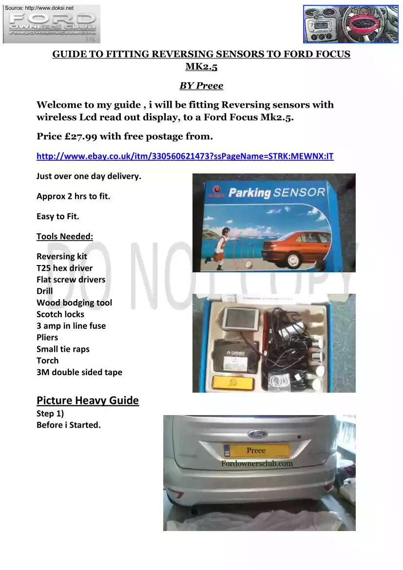
Source: http://www.doksinet GUIDE TO FITTING REVERSING SENSORS TO FORD FOCUS MK2.5 BY Preee Welcome to my guide , i will be fitting Reversing sensors with wireless Lcd read out display, to a Ford Focus Mk2.5 Price £27.99 with free postage from http://www.ebaycouk/itm/330560621473?ssPageName=STRK:MEWNX:IT Just over one day delivery. Approx 2 hrs to fit. Easy to Fit. Tools Needed: Reversing kit T25 hex driver Flat screw drivers Drill Wood bodging tool Scotch locks 3 amp in line fuse Pliers Small tie raps Torch 3M double sided tape Picture Heavy Guide Step 1) Before i Started. Source: http://www.doksinet Step 2) Firstly like to thank Lenny for a small tip he told me . On a Mk25 Focus on the inside of the of the rear bumper are four circle markings where the sensors if factory fitted would be , you do not have to do any scary measuring or lining up. See pictures below , as it was dirty behind there , rubbing my fingers across highlighted the circle’s There are four , one each
side above the reversing light and fog light and 2 in the middle approx 400mm apart. Using a wood Bodging tool (sharp point) , and a torch i centered the tool in the center of each circle and gently pushed and twisted until on the outside of the bumper i could feel a slight lump appearing , not pushing all the way through to make a hole. These lumps would be my guide for drilling and also to check if it looked ok before drilling. See pictures below. Source: http://www.doksinet Using the wood bodging tool i then did the same from the outside of the bumper to start the hole ready for drilling to avoid any chance of slipping with the drill. Source: http://www.doksinet Step 3) With the supplied Drill bit that comes with the Kit , i drilled the first holes , do not apply too much pressure as the drill bit is like a hot knife through butter , once you have drilled each hole , clean all the plastic off the drill bit as it tends to melt on. Wipe each area clean and remove any plastic
bits on the inner hole to allow a smooth fitment. Step 4) Reading the instructions , the unit requires in this case 4 sensors , they are letter A,B,C and D , Starting with letter A for Near Side (above reverse) , un-wrap the cable and feed through the hole , gently place the sensor inside the hole but do not push home yet. Repeat this moving right to left B ,C and D. You do not need the supplied angle spacers. Source: http://www.doksinet All four holes drilled and cleaned Source: http://www.doksinet All four Sensors in place Source: http://www.doksinet Step 5 Push all the sensors home while slightly pulling from the inside to get a tight fit. Do not pull on the cables. From underneath using tie wraps daisy chain the cables together with the tie wraps threading through across the top side of the bumper bar and gather them together by the reversing light. Inside the boot , remove the side panel using a T25 hex driver bit , take out the two screws , then using a flat screw
driver prize off the seat belt surround plastic panel and slide it down the seat belt. Remove the boot water seal rubber and then gently pull the large panel forward until it un-clips. Remove the small panel as per the picture, this will give you access to the reversing light cable and grommet. Source: http://www.doksinet Source: http://www.doksinet Pull the grommet out and make a hole in the grommet big enough for the four cables to go through. Then from underneath feed all four cables through the grommet, then secure the cables underneath again with tie wraps away from any metal that they could rub against. Source: http://www.doksinet Step 6) Connect all of the Sensor cables starting with A through to D, they are lettered so easy to see where they connect. Undo the earth 10 mm bolt and wrap the earth cable between the two ringed connections and tighten down. Remove the insulation tape from around the reversing cables and connect the position feed to the Green/Yellow cable via
a scotch lock. Plug in the power connector and Test the System. Source: http://www.doksinet Source: http://www.doksinet Step 7) Using the supplied 3M double side pad , fix one side to the control unit and then fix the unit to the inside of the rear panel. Source: http://www.doksinet Refit the Side panels making sure the cables are safely tucked behind, also refit the small panel and the seat belt panel. Insert the two T25 screws and tighten up Replace the boot rubber seal making sure you pull the lip of the rubber around the edges of the panels; rear of the car is now finished. Source: http://www.doksinet Sensors have a nice clean look to them. Step 8) The LCD control display has a AUX power plug and a stand for Dash mounting; i did not want to use the AUX plug or the stand as i wanted to fit the display above the interior mirror. Firstly cut the cable off leaving about 8 inches. Undo the four screws on the LCD and remove the back. Using a hacksaw, cut a groove out so
the cable can be moved to the top of the unit allowing it to be hidden easier. Source: http://www.doksinet Move the cable from the bottom of the unit to the top and replace the back and four screws. Step 8) Using two small flat headed screw drivers prize the interior light unit out working your way around slowly a bit a t a time until the unit comes free. Solder or join the 3amp Fused connector to the Positive side of the LCD and slide up under the head lining just above the mirror and feed the cable through to the interior light unit. Using a 10 mm socket undo the earth point bolt and attach the Black/red earth cable to the earth point and tighten the bolt down. Attach the positive red wire of the LCD to the Single wire positive of the interior light unit. Now with 3M double sided tape fix along the top of the LCD and then push onto the head lining and pull the cable from the interior light side for a tight fitment. Replace the interior light unit. Position the car in a clear
space, place in reverse with the ignition on and open the windows and test each of the sensors by placing an object at different distances away. Source: http://www.doksinet All done Thank you for looking at my Guide and sorry for writing all across the pictures but some lazy so and so from another forum has been stealing guides and not showing any credit Regards Preee