A doksi online olvasásához kérlek jelentkezz be!
A doksi online olvasásához kérlek jelentkezz be!
Nincs még értékelés. Legyél Te az első!
Mit olvastak a többiek, ha ezzel végeztek?


Tartalmi kivonat
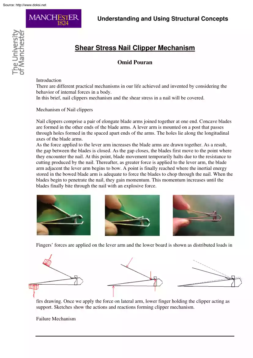
Source: http://www.doksinet Understanding and Using Structural Concepts Shear Stress Nail Clipper Mechanism Omid Pouran Introduction There are different practical mechanisms in our life achieved and invented by considering the behavior of internal forces in a body. In this brief, nail clippers mechanism and the shear stress in a nail will be covered. Mechanism of Nail clippers Nail clippers comprise a pair of elongate blade arms joined together at one end. Concave blades are formed in the other ends of the blade arms. A lever arm is mounted on a post that passes through holes formed in the spaced apart ends of the arms. The holes lie along the longitudinal axes of the blade arms. As the force applied to the lever arm increases the blade arms are drawn together. As a result, the gap between the blades is closed. As the gap closes, the blades first move to the point where they encounter the nail. At this point, blade movement temporarily halts due to the resistance to cutting produced
by the nail. Thereafter, as greater force is applied to the lever arm, the blade arm adjacent the lever arm begins to bow. A point is finally reached where the inertial energy stored in the bowed blade arm is adequate to force the blades to chop through the nail. When the blades begin to penetrate the nail, they gain momentum. This momentum increases until the blades finally bite through the nail with an explosive force. Fingers’ forces are applied on the lever arm and the lower board is shown as distributed loads in firs drawing. Once we apply the force on lateral arm, lower finger holding the clipper acting as support. Sketches show the actions and reactions forming clipper mechanism Failure Mechanism Source: http://www.doksinet Understanding and Using Structural Concepts As far as body to which forces are applied is nail, its behavior illustrates the thin planes are subjected to two inclined forces. Forces applied by blade arms at 45 degrees along the plane passing through
the same direction into the body are shown in the drawing. As the maximum shear stress occurs in the plane has 45 degree angle with the vertical cross section of the body and blade arms acting in the same direction, shear stress increase from the outer fibers to the neutral axis. Besides in thin objects there is no friction resistance When the force increases to reach the ultimate shear resistance of the nail, rupture will happen expectedly. For nail and other similar specimens, the greater the thickness and the width, the greater force needed to be applied on the lever arm to reach the failure point. If we use nail clipper to chop the corner of one plane paper as it is shown in first picture a little force on the lever arm is sufficient to cut it. But as we locate the blades in the middle of the same paper the greater force is needed and it is because of increment in paper area subjected to the force. It is clear when we fold the paper and redo the same action greater force must be
applied due to having thicker depth
 Amerikai novellista, regényíró1899. július 21-én született Oak Parkban.Jómódú polgárcsaládból származott, apja orvos volt, aki fiát korán ránevelte a halászat, vadászat, a sportok iránti szeretetre. Röviddel az érettségi előtt megszökött hazulról, 17 éves korában a Kansas City Star riportere lett, 1918-ban egészségügyi önkéntesként Franciaországba, majd az olasz