A doksi online olvasásához kérlek jelentkezz be!
A doksi online olvasásához kérlek jelentkezz be!
Nincs még értékelés. Legyél Te az első!
Mit olvastak a többiek, ha ezzel végeztek?


Tartalmi kivonat
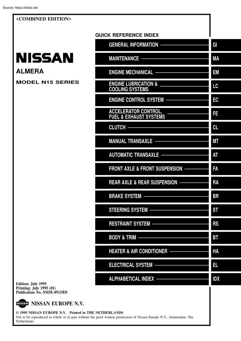
<COMBINED EDITION> QUICK REFERENCE INDEX GENERAL INFORMATION GI MAINTENANCE MA ALMERA ENGINE MECHANICAL EM MODEL N15 SERIES ENGINE LUBRICATION & COOLING SYSTEMS LC ENGINE CONTROL SYSTEM EC ACCELERATOR CONTROL, FUEL & EXHAUST SYSTEMS FE CLUTCH CL MANUAL TRANSAXLE MT AUTOMATIC TRANSAXLE AT FRONT AXLE & FRONT SUSPENSION FA REAR AXLE & REAR SUSPENSION RA BRAKE SYSTEM BR STEERING SYSTEM ST RESTRAINT SYSTEM RS BODY & TRIM BT HEATER & AIR CONDITIONER HA ELECTRICAL SYSTEM EL ALPHABETICAL INDEX IDX Edition: July 1995 Printing: July 1995 (01) Publication No. SM5E-0N15E0 NISSAN EUROPE N.V 1995 NISSAN EUROPE N.V Printed in THE NETHERLANDS Not to be reproduced in whole or in part without the prior written permission of Nissan Europe N.V, Amsterdam, The Netherlands. FOREWORD This manual contains maintenance and repair procedures for NISSAN model N15 series. In order to assure your safety and the efficient functioning of the
vehicle, this manual should be read thoroughly. It is especially important that the PRECAUTIONSin the GI section be completely understood before starting any repair task All information in this manual is based on the latest product information at the time of publication. The right is reserved to make changes in specifications and methods at any time without notice. IMPORTANT SAFETY NOTICE The proper performance of service is essential for both the safety of the technician and the efficient functioning of the vehicle. The service methods in this Service Manual are described in such a manner that the service may be performed safely and accurately. Service varies with the procedures used, the skills of the technician and the tools and parts available. Accordingly, anyone using service procedures, tools or parts which are not specifically recommended by NISSAN must first be completely satisfied that neither personal safety nor the vehicle's safety will be jeopardized by the service
method selected. pe"fl NISSAN MOTOR CO., LTD Overseas Service Department Tokyo, Japan GENERAL INFORMATION • SECTION GI CONTENTS PRECAUTIONS Supplemental Restraint System (SRS) "AIR BAG" (Dual Air Bag System) Supplemental Restraint System (SRS) "AIR BAG" (Single Air Bag System) Precautions for NATS V2.0 (For Gasoline Engine Model) General Precautions Precautions for Multiport Fuel Injection System or ECCS Engine Precautions for Three Way Catalyst Engine Oils Precautions for Fuel HOW TO USE THIS MANUAL HOW TO READ WIRING DIAGRAMS Sample/Wiring Diagram - EXAMPL Description Wiring Diagram Codes (Cell Codes) HOW TO PERFORM EFFICIENT DIAGNOSIS FOR AN ELECTRICAL INCIDENT Work Flow Incident Simulation Tests Circuit Inspection 2 2 2 3 3 5 5 5 6 7 9 9 11 17 18 18 19 23 HOW TO FOLLOW FLOW CHART IN TROUBLE DIAGNOSES CONSULT CHECKING SYSTEM Function and System Application Lithium Battery Replacement. Checking Equipment IDENTIFICATION INFORMATION Model
Variation Identification Number Dimensions Wheels and Tires LIFTING POINTS AND TOW TRUCK TOWING Preparation Board-on Lift Garage Jack and Safety Stand 2-pole Lift Tow Truck Towing TIGHTENING TORQUE OF STANDARD BOLTS SAE J1930 TERMINOLOGY LIST SAE J1930 Terminology List. 29 32 32 32 32 33 33 36 39 39 .40 40 40 41 42 43 44 45 45 PRECAUTIONS Observe the following servicing. precautions to ensure safe and proper Supplemental Restraint System (SRS) "AIR BAG" (Dual Air Bag System) The Supplemental Restraint System" Air Bag" used along with a seat belt, helps to reduce the risk or severity of injury to the driver and front passenger in a frontal collision. The Supplemental Restraint System consists of air bag modules (located in the center of the steering wheel and on the instrument panel on the passenger side), a diagnosis sensor unit, warning lamp, wiring harness and spiral cable. Information necessary to service the system safely is included in the RS section
of this Service Manual WARNING: • To avoid rendering the SRS inoperative, which could increase the risk of personal injury or death in the event of a collision which would result in air bag inflation, all maintenance must be performed by an authorized NISSAN dealer. • Improper maintenance, including incorrect removal and installation of the SRS, can lead to personal injury caused by unintentional activation of the system. • Do not use electrical test equipment on any circuit related to the SRS unless instructed to in this Service Manual. SRS wiring harnesses are covered with yellow insulation either just before the harness connectors or for the complete harness, for easy identification. Supplemental Restraint System (SRS) "AIR BAG" (Single Air Bag System) The Supplemental Restraint System "Air Bag" and used along with a seat belt, helps to reduce the risk or severity of injury to the driver in a frontal collision. The Supplemental Restraint System consists of
an air bag module (located in the center of the steering wheel), a diagnosis sensor unit, warning lamp, wiring harness and spiral cable. Information necessary to service the system safely is included in the RS section of this Service Manual WARNING: • To avoid rendering the SRS inoperative, which could increase the risk of personal injury or death in the event of a collision which would result in air bag inflation, all maintenance must be performed by an authorized NISSAN dealer. • Improper maintenance, including incorrect removal and installation of the SRS, can lead to personal injury caused by unintentional activation of the system. GI-2 PRECAUTIONS • Do not use electrical test equipment on any circuit related to the SRS unless instructed to in this Service Manual. Precautions for NATS V2.0 (For Gasoline Engine Model) NATS (Nissan Anti-Theft System) SGI916 NATS V2.0 will immobilize the engine if someone tries to start it without the registered key of NATS V2.0 Both of
the originally supplied ignition key IDs have been NATS registered. The NATS security indicator is located on the instrument panel. The indicator blinks when the ignition switch is in "OFF" or "ACC" position. Therefore, NATS warns outsiders that the vehicle is equipped with the anti-theft system • When NATS detects trouble, the malfunction indicator lamp (MIL) blinks. This blinking indicates that the anti-theft is not functioning, so prompt service is required. • When servicing NATS (trouble diagnoses, system initialisation and additional registration of other NATS ignition key IDs), CONSULT hardware and CONSULT NATS software is necessary. Regarding the procedures of NATS initialisation and NATS ignition key 10 registration, refer to CONSULT operation manual, NATS V2.0 Therefore, CONSULT NATS software (program card and operation manual) must be kept strictly confidential to maintain the integrity of the anti-theft function. • When servicing NATS V2.0 (trouble
diagnoses, system initial isation and additional registration of other NATS ignition key IDs), it may be necessary to re-register original key identification. Therefore, be sure to receive all keys from vehicle owner. A maximum of four key IDs can be registered into NATS. • When failing to start the engine first-time using the key of NATS V2.0, start as follows (1) Turn ignition key to "OFF". (2) Wait approx. 5 seconds (3) Turn ignition key to "START" again while keeping the key apart from any others on key-chain. General Precautions • Do not operate the engine for an extended period of time without proper exhaust ventilation. Keep the work area well ventilated and free of any flammable materials. Special care should be taken when handling any flammable or poisonous materials, such as gasoline, refrigerant gas, etc. When working in a pit or other enclosed area, be sure to properly ventilate the area before working with hazardous materials. Do not smoke while
working on the vehicle. SGI285 GI-3 • PRECAUTIONS General Precautions (Cont'd) • • Before jacking up the vehicle, apply wheel chocks or other tire blocks to the wheels to prevent the vehicle from moving. After jacking up the vehicle, support the vehicle weight with safety stands at the points designated for proper lifting before working on the vehicle. These operations should be done on a level surface. When removing a heavy component such as the engine or transaxle/transmission, be careful not to lose your balance and drop them. Also, do not allow them to strike adjacent parts, especially the brake tubes and master cylinder. • Before starting repairs which do not require battery power: Turn off ignition switch. Disconnect the negative battery terminal. • To prevent serious burns: Avoid contact with hot metal parts. Do not remove the radiator cap when the engine is hot. • Before servicing the vehicle: Protect fenders, upholstery and carpeting with
appropriate covers. Take caution that keys, buckles or buttons do not scratch paint. • Clean all disassembled parts in the designated liquid or solvent prior to inspection or assembly. Replace oil seals, gaskets, packings, O-rings, locking washers, cotter pins, self-locking nuts, etc. with new ones Replace inner and outer races of tapered roller bearings and needle bearings as a set. Arrange the disassembled parts in accordance with their assembled locations and sequence. Do not touch the terminals of electrical components which use microcomputers (such as ECMs). Static electricity may damage internal electronic components. SEF289H SGI233 SGI234 • • • • GI-4 PRECAUTIONS General Precautions (Cont'd) • • • • • • After disconnecting vacuum or air hoses, attach a tag to indicate the proper connection. Use only the fluids and lubricants specified in this manual. Use approved bonding agent, sealants or their equivalents when required. Use tools and
recommended special tools where specified for safe and efficient service repairs. When repairing the fuel, oil, water, vacuum or exhaust systems, check all affected lines for leaks. Dispose of drained oil or the solvent used for cleaning parts in an appropriate manner. Precautions for Multiport Fuel Injection System or ECCS Engine • • • Before connecting or disconnecting any harness connector for the multiport fuel injection system or EGM (EGGS control module): Turn ignition switch to "OFF" position. Disconnect negative battery terminal. Otherwise, there may be damage to EGM. Before disconnecting pressurized fuel line from fuel pump to injectors, be sure to release fuel pressure. Be careful not to jar components such as EGM and mass air flow sensor. Precautions for Three Way Catalyst If a large amount of unburned fuel flows into the catalyst, the catalyst temperature will be excessively high. To prevent this, follow the instructions below: • Use unleaded gasoline
only. Leaded gasoline will seriously damage the three way catalyst. • When checking for ignition spark or measuring engine compression, make tests quickly and only when necessary. • Do not run engine when the fuel tank level is low, otherwise the engine may misfire causing damage to the catalyst. Do not place the vehicle on flammable material. Keep flammable material off the exhaust pipe and the three way catalyst Engine Oils Prolonged and repeated contact with used engine oil may cause skin cancer. Try to avoid direct skin contact with used oil If skin contact is .made, wash thoroughly with soap or hand cleaner as soon as possible. HEALTH PROTECTION • • • • PRECAUTIONS Avoid prolonged and repeated contact with oils, particularly used engine oils. Wear protective clothing, including impervious gloves where practicable. Do not put oily rags in pockets. Avoid contaminating clothes, particularly underpants, with oil. • • • Heavily soiled clothing and
oil-impregnated footwear should not be worn. Overalls must be cleaned regularly First Aid treatment should be obtained immediately for open cuts and wounds. Use barrier creams, applying them before each work period, to help the removal of oil from the skin. GI-5 • PRECAUTIONS Engine Oils (ConI' d) • • • • • Wash with soap and water to ensure all oil is removed (skin cleansers and nail brushes will help). Preparations containing lanolin replace the natural skin oils which have been removed. Do not use gasoline, kerosine, diesel fuel, gas oil, thinners or solvents for cleaning skin. If skin disorders develop, obtain medical advice without delay. Where practicable, degrease components prior to handling. Where there is a risk of eye contact, eye protection should be worn, for example, chemical goggles or face shields; in addition an eye wash facility should be provided. ENVIRONMENTAL PROTECTION PRECAUTIONS Burning used engine oil in small space heaters or
boilers can be recommended only for units of approved design. The heating system must meet the requirements of HM Inspectorate of Pollution for small burners of less than 0.4 MW If in doubt check with the appropriate local authority and/or manufacturer of the approved appliance. Dispose of used oil and used oil filters through authorized waste disposal contractors to licensed waste disposal sites, or to the waste oil reclamation trade. If in doubt, contact the local authority for advice on disposal facilities. It is illegal to pour used oil on to the ground, down sewers or drains, or into water courses. The regulations concerning the pollution of the environment will vary between regions. Precautions GASOLINE for Fuel ENGINE: For Europe Unleaded gasoline of at least 95 octane (RON) CAUTION: Do not use leaded gasoline. Using leaded gasoline will damage the catalytic converter. Except Europe Unleaded gasoline of at least 91 octane (RON) DIESEL ENGINE*: Diesel fuel of at least 50
cetane If two types of diesel fuel are available, use summer or winter fuel properly according to the following temperature conditions. • Above (20°F) Summer type diesel fuel. • Below (20°F) Winter type diesel fuel. CAUTION: • Do not use home heating oil, gasoline, or other alternate fuels in your diesel engine. The use of those can cause engine damage. • Do not use summer fuel at temperature below 7°C (20°F). The cold temperatures will cause wax to form in the fuel. As a result, it may prevent the engine from running smoothly. • Do not add gasoline or other alternate fuels to diesel fuel. -rc -rc GI-6 HOW TO USE THIS MANUAL INDEX is provided at the end of this manual so that you can rapidly find the item • • ALPHABETICAL and page you are searching for. REFERENCE INDEX, a black tab (e.g I=J;J ) is provided on the first page You can quickly • AfindQUICK the first page of each section by mating it to the section's black tab. CONTENTS are listed on the
first page of each section . • THE THE TITLE is indicated on the upper portion of each page and shows the part or system . • THE PAGE NUMBER of each section consists of two letters which designate the particular section • and a number (e.g "BR-5") THE LARGE ILLUSTRATIONS are exploded views (See below) and contain tightening torques, lubri• cation points, section number of the PARTS CATALOG (e.g SEC440) and other information necessary to perform repairs The illustrations should be used in reference the appropriate PARTS CATALOG. "Example" SEC. 440 Pad retainer (Upper side) 1] ~ jL"J /~ Torque member ~ / D 54 . to service matters only. When ordering 1'5 • '.5, 40 • '71 Main pin m to sliding portion ~ o Pad retainer (Lower Side)m~ ~ ~ ~ ~ parts, refer to D ~ <~ ---------- I cftJ '(~ i":: Copper washer ,~ /~ ~ ~ ~ 17 - 20 (1.7 - 20, 12 • 14) , ~ Brake hose ~ ~Air V bleeder 1111 7 • 9 (0.7 -
09, 61 - 78) Pin bolt ~ 22 - 31 (2.2 - 32, 16 • 23) -Cylinder body ~-~ Outer shim Piston seal Piston I] m~ ~: N.m (kg-m, ft-Ib) It]. N'm (kg-m, in-Ib) SBR364AC • THE SMALL ILLUSTRATIONS show the important steps- such as inspection, use of special tools, knacks of work and hidden or tricky steps which are not shown in the previous large illustrations. Assembly, inspection and adjustment procedures for the complicated units such as the automatic transaxle or transmission, etc. are presented in a step-by-step format where necessary GI-7 HOW TO USE THIS MANUAL • The following to;J, l I IE! IE! ~ @ * 1I SDS LH, RH FR, RR • SYMBOLS AND ABBREVIATIONS are used: Tightening torque Should be lubricated with grease. Unless otherwise indicated, use recommended multi-purpose grease. Should be lubricated with oil. Sealing point Checking point Always replace after every disassembly. Apply petroleum jelly. Apply ATF. Select with proper thickness. Adjustment is
required. Service Data and Specifications Left-Hand, Right-Hand Front, Rear M/T A/T A/C PIS Tool SAE Manual Transaxle/Transmission Automatic Transaxle/ Transmission Air Conditioner Power Steering Special Service Tools Society of Automotive Engineers, Inc. ATF 01 O2 03 04 00 22 21 12 11 Automatic Transmission Drive range 1st gear Drive range 2nd gear Drive range 3rd gear Drive range 4th gear Overdrive 2nd range 2nd gear 2nd range 1st gear 1st range 2nd gear 1st range 1st gear The UNITS given in this manual are primarily expressed as the Sl UNIT (International and alternatively expressed in the metric system and in the yard/pound system. Fluid System of Unit), "Example" Tightening torque: 59 - 78 N'm (6.0 - 80 kg-m, 43 - 58 ft-Ib) • • • TROUBLE DIAGNOSES are included in sections dealing with complicated components. SERVICE DATA AND SPECIFICATIONS are contained at the end of each section for quick reference of data. The captions WARNING and CAUTION warn
you of steps that must be followed to prevent personal injury and/or damage to some part of the vehicle. WARNING indicates the possibility of personal injury if instructions are not followed. CAUTION indicates the possibility of component damage if instructions are not followed. BOLD TYPED STATEMENTS except WARNING and CAUTION give you helpful information. GI-8 HOW TO READ WIRING DIAGRAMS Sample/Wiring • For Description, Diagram - • EXAMPL - refer to GI-11. G/-EXAMPL-02 !- •• ~Refer to optional splice 4 ~ fjJ - G/R ~o EL.EXAMPL ~"G~'P.g I UG r ~ . BA ~TO GI.EXAMPL04 I t I 1 21 ':@ I I I I RELAY • QID e-:. ~~ BA G/R l!4Jl rn ffi POWER •• POSITION POSITION A B SIGNAL III !.M~--------------L! i~-26------'T UNIT~ "OWP M @]) ~~, MODULE • @D • ~@ @ :MfT models !-~--~-~-~ i~ rnrcrni@) r------------------- I B B ,------------------ ctrn @ B ~ : @ W <ffu@]) GY I :.a-o~: lffu
@) '--------~ ---- --- . I @ Aefer to last page (Foldout page). @.@) @ @D ----~---@ W ffiS:8 cmW5~ SGI904 GI-9 HOW TO READ WIRING DIAGRAMS Sample/Wiring Diagram - EXAMPL - (Cont'd) OPTIONAL SPLICE Optional splice MfT models AfT models L <& lOA (ffi ~L . G/R L .I I 10A (ffi L I I . G/R~ L I CID G/R L G/R I L ~CID ~ IrfJ~.~~m .@) '-II-' I~I@) L I !l o ~ l U ~ RELAY n RELAY @ U @ l!:j:JJ ~ l!:j:JJ SGI858 GI-10 HOW TO READ WIRING DIAGRAMS Description Number Item Description CD Power condition • This shows the condition when the system receives battery positive voltage (can be operated) . @ Fusible link • The double line shows that this is a fusible link. • The open circle shows current flow in, and the shaded circle shows current flow out. <ID Fusible link/fuse location • This shows the location of the fusible link or fuse in the fusible link or fuse box. For arrangement, refer to EL
section ("POWER SUPPLY ROUTING") @ Fuse • The single line shows that this is a fuse. • The open circle shows current flow in, and the shaded circle shows current flow out. CID Current rating • This shows the current rating of the fusible link or fuse . @ Connectors • This shows that connector @) is female and connector @ is male . • The G/R wire is located in the A1 terminal of both connectors. • Terminal number with an alphabet (A1, B5, etc.) indicates that the connector is SMJ connector. Refer to GI-16 rJ) Optional splice • The open circle shows that the splice is optional depending on vehicle application. @ Splice • The shaded circle shows that the splice is always on the vehicle. @ Page crossing • This arrow shows that the circuit continues to an adjacent page. • The A will match with the A on the preceding or next page . @) Common connector • The dotted lines between terminals show that these terminals are part of the same
connector. @ Option abbreviation • This shows that the circuit is optional depending on vehicle application. @ Relay • This shows an internal representation of the relay. For details, refer to EL section ("STANDARDIZED RELAY") . @ Connectors @ Wire color • This shows that the connector is connected to the body or a terminal with bolt or nut. • This shows a code for the color of the wire. BR = Brown B = Black W = White OR = Orange R = Red P = Pink PU = Purple G = Green L = Blue GY = Gray Y = Yellow SB =: Sky Blue CH = Dark Brown LG = Light Green DG = Dark Green When the wire color is striped, the base color is given first, followed by the stripe color as shown below: Example: LlW = Blue with White Stripe @ Option description • This shows a description of the option abbreviation used on the page. @) Switch • This shows that continuity exists between terminals 1 and 2 when the switch is in the A position. Continuity exists between terminals 1 and 3
when the switch is in the B position . @ Assembly parts @ Cell code • Connector terminal in component shows that it is a harness incorporated assembly . • This identifies each page of the wiring diagram by section, system and wiring diagram page number. GI-11 • HOW TO READ WIRING DIAGRAMS Description (Cont'd) Number Item Description • Arrow indicates electric current flow, especially where the direction of standard flow (vertically downward or horizontally from left to right) is difficult to @) Current flow arrow @) System branch follow. • A double arrow" . " shows that current can flow in either direction depending on circuit operation . • This shows that the system branches to another system identified by cell code (section and system) . • This arrow shows that the circuit continues to another page identified by cell code. @ Page crossing @ Shielded line • The line enclosed by broken line circle shows shield wire. @) Component
box in wave line • This shows that another part of the component is also shown on another page (indicated by wave line) within the system. @ Component name • This shows the name of a component. @) Connector number • This shows the connector number . • The letter shows which harness the connector is located in. Example: M: main harness. For detail and to locate the connector, refer to EL section ("Main Harness", "HARNESS LAYOUT"). A coordinate grid is included for complex harnesses to aid in locating connectors . @ Ground (GND) • The line spliced and grounded under wire color shows that ground line is spliced at the grounded connector. @ Ground (GND) • This shows the ground connection. @) Connector views • This area shows the connector faces of the components in the wiring diagram on the page. @) Common component • Connectors enclosed in broken line show that these connectors belong to the same component. @l Connector color •
This shows a code for the color of the connector. For code meaning, refer to wire color codes, Number @ of this chart. @ Fusible link and fuse box • The C will match with the C on another page within the system other than the next or preceding pages. • This shows the arrangement of fusible link(s) and fuse(s), used for connector views of "POWER SUPPLY ROUTING" in EL section. The open square shows current flow in, and the shaded square shows current flow out. @ Reference area • This shows that more information on the Super Multiple Junction (SMJ) and Joint Connectors (J/C) exists on the foldout page. Refer to GI-16 for details GI-12 HOW TO READ WIRING DIAGRAMS Description (Cont'd) CONNECTOR Example View from terminal side Connector symbol ~ Direction mark [:it SYMBOLS Most of connector symbols in wiring diagrams are shown from the terminal side. • Connector symbols shown from the terminal side are enclosed by a single line. • Connector symbols
shown from the harness side are enclosed by a double line and followed by the direction mark~ View from harness side Connector symbol ~I Direction mark lit Connector 8GI364 Male and female terminals • Connector guides for male terminals are shown in black and Example Male termlnar ~ G'id'V Connector symbol female terminals Connector Female terminal Guide Connector symbol Connector 8GI363 GI-13 in white in wiring diagrams. • HOW TO READ WIRING DIAGRAMS Description (Cont'd) SWITCH POSITIONS Normally open Switches are shown in wiring diagrams as if the vehicle the "normal" condition. A vehicle is in the "normal" condition when: • ignition switch is "OFF", • doors, hood and trunk lid/back door are closed, • pedals are not depressed, and • parking brake is released. is in Normally closed 5GI860 DETECTABLE VEHICLE SPEED SENSOR Y @ ~ lill-G G~ llli-G-R~ I~I SPEED OMETER Y/G @Z) .,= I - Y/G
LINES In some wiring diagrams, two kinds of lines, representing wires, with different weight are used. • A line with regular weight (wider line) represents a "detectable line for DTC (Diagnostic Trouble Code)". A "detectable line for DTC" is a circuit in which ECM (ECCS control module) can detect its malfunctions with the on-board diagnostic system. • A line with less weight (thinner line) represents a "non-detectable line for DTC", A "non-detectable line for DTC" is a circuit in which ECM cannot detect its malfunctions with the on-board diagnostic system. : Detectable line for DTC : Non-detectable line for DTC 26 VSP ECM (ECCS CONTROL MODULE) [] LINES AND NON-DETECTABLE @) SGI862 GI-14 HOW TO READ WIRING DIAGRAMS Description (Cont'd) MULTIPLE SWITCH The continuity of multiple switch is described in two ways as shown below. • The switch chart is used in schematic diagrams. • The switch diagram is used in wiring diagrams.
Example (SWITCH CHART) WIPER SWITCH WIPER SWITCH f' f 80th switches are turned in combination. Continuity circuit of wiper switch SWITCH POSITION CONTINUITY CIRCUIT OFF 3-4 INT 3-4,5-6 LO 3-6 HI 2-6 WASH 1-6 SGI875 GI-15 • HOW TO READ WIRING DIAGRAMS Description (Cont'd) FOLDOUT PAGE The foldout page should be opened when reading wiring diagram. Super multiple junction (SMJ) In wiring diagram, connectors consisting of terminals having terminal numbers with an alphabet (81, DO, etc.) are SMJ connectors If connector numbers are shown in Reference Area, these connector symbols are not shown in Connector Area. For terminal arrangement of these connectors, refer to the foldout page at the end of this manual. Joint connector Joint connector symbols are shown in Connector Area in the wiring diagram also carries inside wiring layout together with such joint connector symbols. concerned. Foldout page Example Super Multiple Junction (SMJ) L----S (Main I I
R harness) 01 El FIGl A2B2 C2 02 E2 F2 G2 A3B3C3 @ BR A4B4 5 B5 1~~ ~ 5 1~1 . @ID L (Engine AlB1Cl A6B6 F4G4 F5 5 G4F4 G5 F5 F6G6 G6 F6 F7 A8B8C8 E8F8G8 G8F8 E8 E9F9G9 G9 F9 E 9 09 7 r-BR Wirin Diagram ~r- @) @ 09 C9 89 A9 CO BO AO (Engine room harness) BR----{ STARTING SYSTEM CJ OCh~' 'tffB' @) Qfu@ B7A7 C8 88 A8 GO FO EO 0 (Main harness) SUPER MULTIPLE UNCTION (SMJ) JOINT CONNECTOR Terminal Ar angement Terminal Arrangement [Jcheck @(3) B4A4 B5 A5 86 A6 G7F7 AO BO CO DO EO FO GO STARTI G SYSTEM C A7B7 A989C9 01 Cl Bl Al 2F2E2 C2B2A2 02 G3 F3 E3 C3 B3 A3 E3F3G3 0 BR Iroom I harness) @] Gl Fl El o [J * * r::t::rrm::m:J 'M'i' [ill]II!J ~ *~=fH+H=1 [II rDI.TI:IImP [ill]![ill] @g) @) rll" ~ ! ! ! I ! I II !I I ~lllll!I!!lIllbV 'J ~ ~ y "-)-~ Connector Area Reference Area: Refer to the foldout page for the terminal arrangement of the connectors shown here in the
"Reference Area". SG1859-A GI-16 HOW TO READ WIRING DIAGRAMS Wiring Diagram Codes (Cell Codes) Use the chart below to 'find out what each wiring diagram code stands for, Code Section Wiring Diagram Name AACIV EC IACV-AAC Valve ABS BR Anti-lock Brake System A/C HA Manual Air Conditioner A/CCUT EC Air Conditioner A/T AT AIM Code Wiring Diagram Name EC Knock Sensor LKUP EC Torque Converter Clutch Solenoid Valve LOAD EC Load Signal Automatic Transmission MAFS EC Mass Air Flow Sensor EL Headlamp System MAIN EC Main Power Supply and Ground Circuit AIRREG EC IACV-Air Regulator AT/C EC A/T Control METER EL Speedometer, Tachometer, and Fuel Gauges AUDIO EL Audio BACK/L EL Back-up Lamp MIL EC MIL, Data Link Connector For CONSULT CHARGE EL Charging System MIRROR EL DOOR MIRROR CHIME EL Warning Chime NATS EL NISSAN ANTI-THEFT SYSTEM CMPS EC Camshaft Position Sensor 02S EC OXYGEN SENSOR COOllF EC Cooling
Fan Control PGCIV EC DEF EL Rear Window Defogger EVAP CANISTER PURGE CONTROL SOLENOID VALVE D/LOCK EL Power Door Lock PLA EC PARTIAL LOAD ADVANCE CONTROL DTRL EL PNP/SW EC POWER EL POWER SUPPLY ROUTING PST/SW EC POWER STEERING OIL PRESSURE SWITCH R/FOG EL REAR FOG LAMP SROOF EL SUN ROOF SRS RS SUPPLEMENTAL RESTRAINT SYSTEM S/SIG EC START SIGNAL Headlamp - KS Section Cut Control Temp. With Daytime Light System PARK/NEUTRAL POSITION SWITCH Engine Coolant Temperature ECTS EC EGRCIV EC FCUT EC Fuel Cut Solenoid Valve F/FOG EL Front Fog Lamp FICO EC IACV-FICD Solenoid Valve F/PUMP EC Fuel Pump GLOW EC Quick-glow system START EL STARTING SYSTEM H/LAMP EL Headlamp - Without Daytime Light System STOP/L EL STOP LAMP H/SEAT EL Heated Seat TAllIL EL CLEARANCE, LICENSE, AND TAIL LAMPS HEAT HA Heater TPS EC THROTTLE POSITION SENSOR HLC EL Headlamp Washer H02S EC Heated Oxygen Sensor TURN EL TURN SIGNAL AND
HAZARD WARNING LAMPS HORN EL Horn, Cigarette Lighter, Clock VSS EC VEHICLE SPEED SENSOR IATS EC Intake Air Temperature VTC EC VTC SOLENOID VALVE IGN/SG EC Ignition Signal WARN EL WARNING LAMPS ILL EL Illumination WINDOW EL POWER WINDOW INJECT EC Injector WIPER EL FRONT WIPER AND WASHER Interior, Spot and Trunk Room WIP/R EL REAR WIPER AND WASHER INT/L EL Sensor EGR and canister Control Solenoid Valve Sensor Lamps GI-17 • HOW TO PERFORM EFFICIENT DIAGNOSIS FOR AN ELECTRICAL INCIDENT Work Flow - - - - - - - - - - - - - - - - - - - --------------------- STEP 2 ----------------------- - - - - - - - - - --------- - - - - - - - - - STEP 3 - - - - - - - - - - -------------------- - - - - STEP 1 - - - - - - - - - - - - - - - - - - - - STEP 4 STEP 5 STEP 6 SGI838 DESCRIPTION STEP STEP 1 Get detailed information about the conditions and the environment when the incident occurred. The following are key pieces of
information required to make a good analysis: WHAT Vehicle Model, Engine, Transmission and the System (i.e Radio) WHEN Date, Time of Day, Weather Conditions, Frequency. WHERE Road Conditions, Altitude and Traffic Situation. HOW System Symptoms, Operating Conditions (Other Components Interaction). Service History and if any After Market Accessories have been installed. STEP 2 Operate the system, road test if necessary. Verify the parameter of the incident. If the problem can not be duplicated, refer to "Incident Simulation Tests" next page. STEP 3 Get the proper diagnosis materials together including: POWER SUPPLY ROUTING System Operation Descriptions Applicable Service Manual Sections Identify where to begin diagnosis based upon your knowledge of the system operation and the customer comments. STEP 4 Inspect the system for mechanical binding, loose connectors or wiring damage. Determine which circuits and components are involved and diagnose using the Power
Supply Routing and Harness Layouts. STEP 5 Repair or replace the incident circuit or component. STEP 6 Operate the system in all modes. Verify the system works properly under all conditions Make sure you have not inadvertently created a new incident during your diagnosis or repair steps. GI-18 HOW TO PERFORM EFFICIENT DIAGNOSIS FOR AN ELECTRICAL INCIDENT Incident Simulation Tests INTRODUCTION Sometimes the symptom is not present when the vehicle is brought in for service. If possible, re-create the conditions present at the time of the incident. Doing so may help avoid a No Trouble Found Diagnosis The following section illustrates ways to simulate the conditionslenvironment under which the owner experiences an electrical incident. The section is broken into the six following • Vehicle vibration • Heat sensitive • Freezing • Water intrusion • Electrical load • Cold or hot start up Get a thorough description tions of the problem. topics: of the incident from the
customer. It is important for simulating the condi- VEHICLE VIBRATION The problem may occur or become worse while driving on a rough road or when engine is vibrating (idle with AIC on). In such a case, you will want to check for a vibration related condition Refer to the illustration below. Connectors & harness Determine which connectors and wiring harness would affect the electrical system you are inspecting. Gently shake each connector and harness while monitoring the system for the incident you are trying to duplicate. This test may indicate a loose or poor electrical connection Hint Connectors can be exposed to moisture. It is possible to get a thin film of corrosion on the connector terminals. A visual inspection may not reveal this without disconnecting the connector If the problem occurs intermittently, perhaps the problem is caused by corrosion. It is a good idea to disconnect, inspect and clean the terminals on related connectors in the system. Sensors & relays
Gently apply a slight vibration to sensors and relays in the system you are inspecting. This test may indicate a loose or poorly mounted sensor or relay. Vibration test Tap gently. Bend gently. GI-19 8GI839 • HOW TO PERFORM EFFICIENT DIAGNOSIS FOR AN ELECTRICAL INCIDENT Incident Simulation Tests (Cont'd) Possible cause I, II ::0 Po 1/ I~ II ':!J Any probe entering the terminal may enlarge the contact spring opening creating an intermittent signal. Intermittent signals through pierced insulation Enlarged Proper crimp Normal DEFORMED (ENLARGED) FEMALE TERMINALS Insulation not removed Wire strands missing DEFECTIVE INSULATION STRIPPING Female half Seal Check for unlocked terminals by pulling each wire at the end of the connector. Intermittent contact TERMINAL NOT PROPERLY SEATED [1/ / SGI840 Tester probe SGI841 When probing a connector it is possible to enlarge the contact spring opening. If this occurs it may create an intermittent signal in
the circuit When probing a connector, use care not to enlarge the opening. The probe of the Digital Multimeter (DMM) may not fit into the connector cavity. In such cases make an extension of a "T" pin and probe it from the harness side of the connector. Most DMMs have accessory alligator clips Slide these over the probe to allow clipping the "T" pin for a better contact. If you have any difficulty probing a terminal, inspect the terminal. Ensure you have not accidentally opened the contact spring or pulled a wire loose. GI-20 HOW TO PERFORM EFFICIENT DIAGNOSIS FOR AN ELECTRICAL INCIDENT Incident Simulation Tests (Cont'd) Engine compartment There are several reasons a vehicle or engine vibration could cause an electrical complaint. Some of the things to check for are: • • • • • Connectors not fully seated. Wiring harness not long enough and is being stressed to engine vibrations or rocking. Wires laying across brackets or moving components.
Loose, dirty or corroded ground wires. Wires routed too close to hot components. due To inspect components under the hood, start by verifying the integrity of ground connections. (Refer to GROUND INSPECTION described later) First check that the system is properly grounded. Then check for loose connection by gently shaking the wiring or components as previously explained. Using the wiring diagrams inspect the wiring for continuity. Behind the instrument panel An improperly routed or improperly clamped harness can become pinched during accessory installation. Vehicle vibration can aggravate a harness which is routed along a bracket or near a screw. Under seating areas An unclamped or loose harness can cause wiring to be pinched by seat components (such as slide guides) during vehicle vibration. If the wiring runs under seating areas, inspect wire routing for possible damage or pinching Heating HEAT SENSITIVE test The owner's problem may occur during hot weather or after car
has sat for a short time. In such cases you will want to check for a heat sensitive condition. To determine if an electrical component is heat sensitive, heat the component with a heat gun or equivalent. Do not heat components above 60°C (140°F). If incident occurs while heating the unit, either replace or properly insulate the component. Do not heat above 60°C (140°F). 8GI842 GI-21 • HOW TO PERFORM EFFICIENT DIAGNOSIS FOR AN ELECTRICAL INCIDENT Incident Simulation Tests (Cont'd) FREEZING Freezing test Water in connector Solenoid SGI843 The customer may indicate the incident goes away after the car warms up (winter time). The cause could be related to water freezing somewhere in the wiring/electrical system. There are two methods to check for this. The first is to arrange for the owner to leave his car overnight. Make sure it will get cold enough to demonstrate his complaint. Leave the car parked outside overnight. In the morning, do a quick and thorough diagnosis
of those electrical components which could be affected. The second method is to put the suspect component into a freezer long enough for any water to freeze. Reinstall the part into the car and check for the reoccurrence of the incident. If it occurs, repair or replace the component. WATER INTRUSION Water Intrusion test The incident may occur only during high humidity or in rainy/ snowy weather. In such cases the incident could be caused by water intrusion on an electrical part. This can be simulated by soaking the car or running it through a car wash. Do not spray water directly on any electrical components. SGI844 ELECTRICAL Electrical load test LOAD The incident may be electrical load sensitive. Perform diagnosis with all accessories (including A/C, rear window defogger, radio, fog lamps) turned on. COLD OR HOT START UP AIC On some occasions an electrical incident may occur only when the car is started cold. Or it may occur when the car is restarted hot shortly after being
turned off. In these cases you may have to keep the car overnight to make a proper diagnosis. SGI845 GI-22 HOW TO PERFORM EFFICIENT DIAGNOSIS FOR AN ELECTRICAL INCIDENT Circuit Inspection INTRODUCTION In general, testing electrical circuits is an easy task if it is approached in a logical and organized method. Before beginning it is important to have all available information on the system to be tested. Also, get a thorough understanding of system operation. Then you will be able to use the appropriate equipment and follow the correct test procedure. You may have to simulate vehicle vibrations while testing electrical components. Gently shake the wiring harness or electrical component to do this OPEN A circuit SHORT There are two types of shorts. is open when there is no continuity through a section of the circuit. • SHORT CIRCUIT When a circuit contacts another circuit and causes the normal resistance to change. • SHORT TO GROUND When a circuit contacts a ground
source and grounds the circuit. TESTING FOR "OPENS" IN THE CIRCUIT Before you begin to diagnose and test the system, you should rough sketch a schematic of the system. This will help you to logically walk through the diagnosis process. Drawing the sketch will also reinforce your working knowledge of the system. Inspection for opens [YJ (Voltage check) - + DMM Ll I I B + SIDE I L ~SE. ~L9~K I -,---- OPEN A I I -.J [ill DMM SGI846 Continuity check method The continuity check is used to find an open in the circuit. The Digital Multimeter (DMM) set on the resistance function will indicate an open circuit as over limit (OL, no beep tone or no ohms symbol). Make sure to always start with the DMM at the highest resistance level. To help in understanding the diagnosis of open circuits please refer to the schematic above. 1. 2. Disconnect the battery negative cable. Start at one end of the circuit and work your way to the.other end (At the fuse block in this
example) 3. Connect one probe of the DMM to the fuse block terminal on the load side 4. Connect the other probe to the fuse block (power) side of SW1 Little or no resistance will indicate that portion of the circuit has good continuity. If there were an open in the circuit, the DMM would indicate an over limit or infinite resistance condition. (point A) 5. Connect the probes between SW1 and the relay Little or no resistance will indicate that portion of the circuit has good continuity. If there were an open in the circuit, the DMM would indicate an over limit or infinite resistance condition. (point B) 6. Connect the probes between the relay and the solenoid Little or no resistance will indicate that portion of the circuit has good continuity If there were an open in the circuit, the DMM would indicate an over limit or infinite resistance condition. (point C) Any circuit can be diagnosed using the approach in the above example. GI-23 • HOW TO PERFORM EFFICIENT DIAGNOSIS FOR AN
ELECTRICAL INCIDENT Circuit Inspection (Cont'd) Voltage check method To help in understanding the diagnosis of open circuits please refer to the previous schematic. In any powered circuit, an open can be found by methodically checking the system for the presence of voltage. This is done by switching the DMM to the voltage function 1. Connect one probe of the DMM to a known good ground 2. Begin probing at one end of the circuit and work your way to the other end 3. With SW1 open, probe at SW1 to check for voltage voltage; open is further down the circuit than SW1. no voltage; open is between fuse block and SW1 (point A). 4. Close SW1 and probe at relay voltage; open is further down the circuit than the relay. no voltage; open is between SW1 and relay (point B). 5. Close the relay and probe at the solenoid voltage; open is further down the circuit than the solenoid. no voltage; open is between relay and solenoid (point C). Any powered circuit can be diagnosed using the approach in
the above example. TESTING FOR "SHORTS" To simplify the discussion IN THE CIRCUIT of shorts in the system please refer to the schematic below. Inspection for shorts t (Resistance check) IGN "ON" OR "S~:R.T~ RELAY '::~SE BLOCK I I I I B+SIOEl~~-:-~ -= '- ~r-o ~ SHORT [YJ + - SWl DMM A SHORT B (Voltage check) ~I SH~ SW2 1 c SGI847 Resistance check method 1. 2. 3. 4. 5. 6. Disconnect the battery negative cable and remove the blown fuse. Disconnect all loads (SW1 open, relay disconnected and solenoid disconnected) powered through the fuse. Connect one probe of the ohmmeter to the load side of the fuse terminal. Connect the other probe to a known good ground. With SW1 open, check for continuity. continuity; short is between fuse terminal and SW1 (point A). no continuity; short is further down the circuit than SW1. Close SW1 and disconnect the relay. Put probes at the load side of fuse terminal and a known good ground. Then,
check for continuity continuity; short is between SW1 and the relay (point B), no continuity; short is further down the circuit than the relay. Close SW1 and jump the relay contacts with jumper wire. Put probes at the load side of fuse terminal and a known good ground Then, check for continuity continuity; short is between relay and solenoid (point C). no continuity; check solenoid, retrace steps. GI-24 HOW TO PERFORM EFFICIENT DIAGNOSIS FOR AN ELECTRICAL INCIDENT Circuit Inspection (Cont'd) Voltage check method 1. 2. 3. 4. 5. Remove the blown fuse and disconnect all loads (i.e SW1 open, relay disconnected and solenoid disconnected) powered through the fuse. Turn the ignition key to the ON or START position. Verify battery voltage at the B + side of the fuse terminal (one lead on the B + terminal side of the fuse block and one lead on a known good ground). With SW1 open and the DMM leads across both fuse terminals, check for voltage. voltage; short is between fuse block
and SW1 (point A). no voltage; short is further down the circuit than SW1. With SW1 closed, relay and solenoid disconnected and the DMM leads across both fuse terminals, check for voltage. voltage; short is between SW1 and the relay (point B). no voltage; short is further down the circuit than the relay. With SW1 closed, relay contacts jumped with fused jumper wire check for voltage. voltage; short is down the circuit of the relay or between the relay and the disconnected solenoid (point C). no voltage; retrace steps and check power to fuse block. GROUND INSPECTION Ground connections are very important to the proper operation of electrical and electronic circuits. Ground connections are often exposed to moisture, dirt and other corrosive elements. The corrosion (rust) can become an unwanted resistance. This unwanted resistance can change the way a circuit works. Electronically controlled circuits are very sensitive to proper grounding. A loose or corroded ground can drastically affect
an electronically controlled circuit. A poor or corroded ground can easily affect the circuit Even when the ground connection looks clean, there can be a thin film of rust on the surface When inspecting a ground connection follow these rules: 1. Remove the ground bolt screw or clip 2. Inspect all mating surfaces for tarnish, dirt, rust, etc 3. Clean as required to assure good contact 4. Reinstall bolt or screw securely 5. Inspect for "add-on" accessories which may be interfering with the ground circuit 6. If several wires are crimped into one ground eyelet terminal, check for proper crimps Make sure all of the wires are clean, securely fastened and providing a good ground path. If multiple wires are cased in one eyelet make sure no ground wires have excess wire insulation. Ground Inspection • • Remove boll (screw). • Inspect mating surfaces for tarnish. dirt rust etc Clean as required to assure good contact. Reinstall bolt (screw) securely. SGI853 GI-25 •
HOW TO PERFORM EFFICIENT DIAGNOSIS FOR AN ELECTRICAL INCIDENT Circuit Inspection (Cont'd) VOLTAGE DROP TESTS Voltage drop tests are often used to find components or circuits which have excessive resistance. A voltage drop in a circuit is caused by a resistance when the circuit is in operation. Check the wire in the illustration. When measuring resistance with ohmmeter, contact by a single strand of wire will give reading of 0 ohms. This would indicate a good circuit When the circuit operates, this single strand of wire is not able to carry the current. The single strand will have a high resistance to the current. This will be picked up as a slight voltage drop Unwanted resistance can be caused by many situations as follows: Undersized wiring (single strand example) Corrosion on switch contacts Loose wire connections or splices. If repairs are needed always use wire that is of the same or larger gauge. Measuring 1. 2. 3. voltage drop - Accumulated method Connect the voltmeter
across the connector or part of the circuit you want to check. The positive lead of the voltmeter should be closer to power and the negative lead closer to ground. Operate the circuit. The voltmeter will indicate how many volts are being used to "push" current through that part of the circuit. Note in the illustration that there is an excessive 4.1 volt drop between the battery and the bulb Symptom: Dim bulb or no operation o (zero) ohm resistance between switch and bulb ------------------~ -- I OV I ~~~~ DMM -, 12V 11.9V: 'I I -- Load) Switch -- Ground Connection with high resistance l ; Battery t • Ground SGI848 Measuring voltage drop - Step by step The step by step method is most useful for isolating excessive drops in low voltage systems (such as those in "Computer Controlled Systems"). Circuits in the "Computer Controlled System" operate on very low amperage. The (Computer Controlled) system operations can be
adversely affected by any variation in resistance in the system. Such resistance variation may be caused by poor connection, improper installation, improper wire gauge or corrosion. The step by step voltage drop test can identify a component or wire with too much resistance. GI-26 HOW TO PERFORM EFFICIENT DIAGNOSIS FOR AN ELECTRICAL INCIDENT Circuit Inspection (Cont'd) 1. Connect the voltmeter as shown, starting at the battery and working your way around the circuit. 2. An unusually large voltage drop will indicate a component or wire that needs to be repaired. As you can see the illustration above, the poor connection causes a 4 volt drop. The chart that follows illustrates some maximum allowable voltage drops. These values are given as a guideline, the exact value for each component may vary. COMPONENT Wire Ground Connections Switch Contacts VOLTAGE DROP negligible <.001 volts Approx. 0,1 volts Approx. 03 volts SGI854 GI-27 • HOW TO PERFORM EFFICIENT DIAGNOSIS
FOR AN ELECTRICAL INCIDENT Circuit Inspection (Cont'd) Relationship between open/short (high resistance) circuit and the ECM pin control System Description: When the switch is ON, the ECM lights up the lamp. Case 1 TERMINAL: 2 Power supply to light up the lamp TERMINAL: 1 Monitoring of the switch operation (ON/OFF) Battery 2 '-----v--J Short: Open: Lamo FUSE blows. Inoperative lamp '"-----v~----) j ~--~y ECM Short: FUSE blows when switch is ON. Open: Inoperative lamp Short & Open: Inoperative lamp ~ Short: Open: No problem Inoperative lamp High resistance: (Single strand) See below.' Input-output voltage chart Pin Item Condition No. 1 Switch 2 Lamp Voltage In 1:aseof high resistance value [V] such as single strand [V] * Switch Battery Lower than battery voltage ON voltage Approx.8 OFF Approx.O Approx.O Switch Battery Approx.O ON voltage (Inoperative OFF Approx.O Approx.O (Example) lamp) The voltage value is
based on the body ground. : If high resistance exists in the switch side circuit (caused by a single strand), terminal 1 does not detect battery voltage. ECM does not detect the switch is ON even if the switch does turn ON. Therefore the ECM does not supply power to light up the lamp Case 2 TERMINAL: 2 Monitoring of the switch operation (ON/OFF) TERMINAL: 1 Ground control to light up the lamp Lamp Battery Switch 2 o '---v---J Short: Open: ) .----v FUSE blows. Inoperative lamp Short: Open: ECM ~--~v~-- .J Lamp stays ON. Inoperative lamp Pin Item Condition 1 Lamp Switch Voltage In case of high resistance value [V] such as single strand [V] * Approx.O ON OFF "---y-----.J Short: Open: No problem Inoperative lamp High resistance: See below. (Single strand)' Input-output voltage chart No. Short: Lamp stays ON. (Same as the switch ON) Open: Inoperative lamp Battery voltage (I noperat ive lamp) Battery Battery voltage voltage 2 Switch
Switch Approx.O ON OFF Higher than 0 Approx. Approx.5 4 (Example) Approx.5 The voltage value is based on the body ground. • : If high resis1ance exists in the switch side circuit (caused by a single strand), terminal 2 does not detect approx. OV ECM does not detect the switch is ON even if the switch does turn ON. Therefore, the ECM does not control ground to light up the lamp SG1849-A GI-28 HOW TO FOLLOW FLOW CHART IN TROUBLE DIAGNOSES NOTICE The flow chart indicates work procedures required to diagnose problems effectively. Observe the following instructions before diagnosing. 1) Use the flow chart after locating probable causes of a problem following the "Preliminary Check", the "Symptom Chart" or the "Work Flow". 2) After repairs, re-check that the problem has been completely eliminated. 3) Refer to Component Parts and Harness Connector Location for the Systems described in each section for identificationl location of components and
harness connectors. 4) Refer to the Circuit Diagram for Quick Pinpoint Check. If you must check circuit continuity between harness connectors in more detail, such as when a sub-harness is used, refer to Wiring Diagram in each individual section and Harness Layout in EL section for identification of harness connectors. 5) When checking circuit continuity, ignition switch should be "OFF" . 6) Before checking voltage at connectors, check battery voltage. After accomplishing the Diagnostic Procedures and Electrical Components Inspection, make sure that all harness connectors are reconnected as they were. 7) Example -=-=~-----------~ ~i5 m. INSPECTION START ~ [YJ Check the following CHECK POWER SUPPLY. 1) Turn ignition switch "ON". 2) Check voltage between terminal @ and ground. items. 1) Harness continuity between camshaft position sensor and battery 2) ECCS relay-1 3) "SR" fusible link 4) Power source for ~Ba"ery voltage should exist. OK
SGI561 2 ~ ECM OISCONNECT 5) Ignition switch 18 Ii) SGI562 CHECK GROUND CIRCUIT. 1) Turn ignition switch "OFF" 2) Disconnect camshaft position sensor harness connector. 3) Check resistance between terminal @ and ground. Resistance: Approximately on NG Check the following items. 1) Harness continuity between camshaft position sensor and ground 2) Ground circuit for ECM OK SG1800-C GI-29 • HOW TO FOLLOW FLOW CHART IN TROUBLE DIAGNOSES HOW TO FOllOW THIS FLOW CHART OJ Work and diagnostic procedure Start to diagnose a problem using procedures indicated in enclosed blocks, as shown in the following example. CHECK POWER SUPPLY. 1) Turn ignition switch "ON". 2) Check voltage between terminal @ and ground. Battery voltage should exist. -+- Check item being performed. } Procedure, steps or measurement results [2] Measurement results Required results are indicated in bold type in the corre. sponding block, as shown below: These have the following
meanings: Battery voltage - 11 . 14V or approximately Voltage: Approximately OV - Less than 1V 12V ~ Cross reference of work symbols in the text and illustrations Illustrations are provided as visual aids for work procedures. For example, symbol indicated in the left upper portion of each illustration corresponds with the symbol in the flow chart for easy identification. More precisely, the procedure under the "CHECK POWER SUPPLY" outlined previously is indicated by an illustration [4J Symbols used in illustrations m m. Symbols included in illustrations refer to measurements or procedures. Before diagnosing a problem, familiarize yourself with each symbol Direction mark Refer to "CONNECTOR SYMBOLS" on GI-13. GI-30 HOW TO FOLLOW FLOW CHART IN TROUBLE DIAGNOSES Key to symbols signifying measurements or procedures Symbol Symbol explanation DISCONNECT Check after disconnecting the connector to be measured. ~8 CONNECT Symbol Symbol explanation Current
should be measured with an ammeter. ~ Check after connecting the connector to be measured. 00 Procedure with CONSULT (lr~~ Insert key into ignition switCh. @ Procedure without CONSULT (lr.~ Remove key from ignition switch. E) AIC switch is "OFF". ~ Turn ignition switch to "OFF" position. AIC switch is "ON". ~ ~ Turn ignition switch to "ON" position. " @:; ~ Turn ignition switch to "START" position. @'~ ~~ Turn ignition switch from "OFF" to "ACC" position. ~~r Turn ignition switch from "ACC" to "OFF" position. ~ Fan switch is "OFF". Apply positive voltage from battery with fuse directly to components. BA; ~ m~'~: , .-= ~(e.- Turn ignition switch from "OFF" to ~~ BAi ~F Turn ignition switch from "ON" to "OFF" position. ~ ~ Do not start engine, or check with engine stopped. ~ Disconnect battery negative
cable. Depress brake pedal. Release brake pedal. Start engine, or check with engine run- Depress accelerator pedal. . ning. .~ Apply parking brake. i!J ~ Release accelerator pedal. . Release parking brake. Pin terminal check for SMJ type ECM and AIT control unit connectors For details regarding the terminal ~ ~ or Cff~H ~ lJ9j lfJJ Drive vehicle. L . "ON" position. ID Fan switch is "ON". (At any position except for "OFF" position) " @J~ OON • Check after engine is warmed up sufficiently. ~ Voltage should be measured with a voltmeter. arrangement, refer to the foldout page. B ~io . [YJ Circuit resistance should be measured with an ohmmeter. GI-31 - ~ lltlllliR ~ t~~~18 CONSULT CHECKING SYSTEM Function and System Application Diagnostic Function test mode ECCS Air bag ASS NATS*1 Work support This mode enables a technician to adjust some devices faster and more accurately by following the
indications on CONSULT. x - - - Self-diagnostic results Self-diagnostic results can be read and erased quickly. x x x x ECU discriminated Classification number of a replacement ECU can be read to No. prevent an incorrect ECU from being installed. - x - - Data monitor Input/Output data in the ECM can be read. x - x - Active test Diagnostic Test Mode in wh.ich CONSULT drives some actuators apart from the ECMs and also shifts some parameters x - x - in a specified range. ECM part number ECM part number can be read. x - x - Function test Conducted by CONSULT instead of a technician to determine whether each system is "OK" or "NG". x - - - Control unit initialisation All registered ignition key IDs in NATS components can be initialised and new IDs can be registered. - - - x Self-function check ECM checks its own NATS communication interface. - - - x x : Applicable *1: NATS: Nissan Anti-Theft System Lithium Battery
Replacement CONSULT contains a lithium battery. When replacing the battery obey the following: WARNING: Replace the lithium battery with SANYO Electric Co., ltd, CR2032 only Use of another battery may present a risk of fire or explosion. The battery may present a fire or chemical burn hazard if mistreated Do not recharge, disassemble or dispose of in fire. Keep the baitery out of reach of children and discard used battery conforming to the local regulations. Checking Equipment When ordering the below equipment, contact your NISSAN distributor. Tool name Description NISSAN CONSULT CD CONSULT unit and accessories @ Program card (EE 940) (AE930)*1, (AE950)2, (NATS-E940)*3 NT004 *1: For Australia *2: Regarding ASS for Australia, a revised program card (AE950) will be applicable to this system in 1995. *3: An order for NATS program card must be placed only with NISSAN EUROPE N.V GI-32 IDENTIFICATION INFORMATION Model Variation For Europe LHO Europe LHD Engine GA14DE GA16DE
CD20 5F 5F AT 5F RS5F30A RSSF31A RL4F03A RS5F31A Transaxle L BAVALBF-EGA LX BAVALDF-EGA BA YALDF-EGA BAYALDA-EGA BVCALDF-NGA SLX BAVALFF-EGA BA YALFF-EGA BAYALFA-EGA BVCALFF-NGA 4-door Sedan BA YALQF-EGA SR 3-door Hatchback L EAVALBF-EGA LX EAVALDF-EGA EA YALDF-EGA EAYALDA-EGA EVCALDF-NGA SLX EAVALFF-EGA EA YALFF-EGA EA YALFA-EGA EVCALFF-NGA SR EAVALQF-EGA EAY ALQF-EGA GTI L FAVALBF-EGA LX FAVALDF-EGA FAYALDF-EGA FAYALDA-EGA FVCALDF-NGA SLX FAVALFF-EGA FAYALFF-EGA FAYALFA-EGA FVCALFF-NGA SR FAVALQF-EGA FAYALQF-EGA 5-door Hatchback For Europe RHO Europe RHD Engine GA14DE CD20 GA16DE SF 5F AT SF RS5F30A RS5F31A RL4F03A RS5F31A Transaxle L BAVARBF-EEA LX BAVARDF-EEA BA YARDF-EEA BA YARDA-EEA BVCARDF-NEA SLX BAVARFF-EEA BA YARFF-EEA BAYARFA-EEA BVCARFF-NEA 4-door Sedan BAYARQF-EEA SR 3-door Hatchback L EAVARBF-EEA LX EAVARDF-EEA SLX EAVARFF-EEA EAYARFF-EEA SR EAVARQF-EEA EA YARQF-EEA GTI
EAYARFA-EEA . L FAVARBF-EEA LX FAVARDF-EEA FAYARDF-EEA FAYARDA-EEA FVCARDF-NEA SLX FAVARFF-EEA FAYARFF-EEA FAYARFA-EEA FVCARFF-NEA SR FAVARQF-EEA FAYARQF-EEA 5-door Hatchback GI-33 • IDENTIFICATION INFORMATION Model Variation (Cont'd) For Australia Australia GA16DE Engine SR20DE 5F RS5F31A 4AT RL4F03A LX BAYARDF-EMA BA YARDA-EMA SLX BA YARFF-EMA BAYARFA-EMA LX FAYARDF-EMA FAYARDA-EMA Q FAYARDF-EMA FAYARDA-EMA SLX FAYARFF-EMA FA YARFA-EMA Transaxle 5F RS5F32A 4AT RL4F03A FBYARUF-EMA FBYARUA-EMA 4-door Sedan 5-door Hatchback SSS Except Europe and Australia RHD Except Europe and Australia GA15DE Engine Transaxle LX GA16DE 5F RS5F30A 4AT RL4F03A BAWARCF-EWA BAWARCA-EWA 4-door Sedan SLX XI FAWARCF-EWA 5F RS5F31A 4AT RL4F03A BAYARGF-EWA BAYARGA-EWA FAYARGF-EWA FAYARGA-EWA FAWARCA-EWA 5-door Hatchback XIR GI-34 IDENTIFICATION INFORMATION Model Variation (Cont'd) Prefix and suffix designations: B AV A L B F
E N15 G A T T A: Standard E: RHO models for Europe G: LHD models for Europe W: RHO models except Europe and Australia M: Australia E: Multiport fuel injection system engine N: Diesel engine Model A: 4-speed automatic transaxle F: 5-speed manual transaxle B: L 0: LX or Q F: SLX C: LX or XI G: SLX or XIR Q:SR U: GTI or SSS L: Left-hand drive R: Right-hand drive A: 2-wheel drive models AV: GA14DE engine AW: GA15DE engine AY: GA16DE engine BY: SR20DE engine VC: CD20 engine B: 4-door Sedan F: 5-door Hatchback E: 3-door Hatchback GI-35 • IDENTIFICATION INFORMATION Identification Number Vehicle identification Emission control information number Vehicle identification plate label SGI908 VEHICLE IDENTIFICATION NUMBER ARRANGEMENT For Europe : JN1 B A N15 U 0 T T T A xxxxxx . ~ehicle serial number o : Stopgap (no meaning) Destination U : Europe Model A : 2-wheel drive Engine type A: GA14DE engine C : GA16DE engine E : SR20DE engine F : CD20 engine
Body type B : 4-door Sedan F : 5-door Hatchback E : 3-door Hatchback Manufacturer JN1 : Nissan, Passenger vehicle GI-36 IDENTIFICATION INFORMATION Identification Number (Cont'd) For Australia JN1 and New Zealand B c N15 A T A 0 T T xxxxxx ~ehicle serial number o : Stopgap (no meaning) Destination A : Australia and New Zealand Model A : 2-wheel drive Engine type B : GA15DE engine C: GA16DE engine E : SR20DE engine Body type B : 4-door Sedan F : 5-door Hatchback Manufacturer JN1 : Nissan, Passenger vehicle Except for Europe, Australia, JN1 B C A New Zealand N15 Z 0 T T T xxxxxx ~ehicle serial number o : Stopgap (no meaning) Destination Z . Except Europe, Australia, New Zealand Model A : 2-wheel drive Engine type B : GA15DE engine C : GA16DE engine Body type B : 4-door Sedan F : 5-door Hatchback Manufacturer JN1 : Nissan, Passenger vehicle GI.37 • IDENTIFICATION INFORMATION Identification Number (Cont'd) IDENTIFICATION PLATE Except Europe
NISSAN MOTOR CO.,L TDJAPAN I it ill 0 ill 1- TYP i 11 ~ it ii:J b CHASS~ NO NO DE CHASIS MODEL MDDELO iliO o ~;::~:~~NlctDN kg .:t;- &, COlOR.iRIM fARBE,POLSl & &, 2Tri'[ NISSAN MOTOR CO., LTD JAPAN I It &, Europe kg ~:,. o ENGINE MOTOR CC ~ ';; Y 3 ;.-TRANS~ AXl£ 7P;;<'. ll!AIIS.EJt: Lilli M4DE IN JAPAN 1 Type approval number 2 Vehicle identification number (Chassis number) 3 Gross vehicle weight 4 Gross combination weight Gross vehicle weight + Gross trailing capacity (Weight) 5 Gross axle weight (Front) 6 Gross axle weight (Rear) 7 Type 8 Body color code 9 Trim color code 10 Model 11 Engine model 12 Engine displacement 13 Transaxle model 14 Axle model SGI704 ENGINE SERIAL NUMBER GA 14DE, GA 15DE and GA16DE engine SR20DE engine CD20 engine £~b-=~~rrf~) (J~~~6 Front c:::? SGI912 MANUAL TRANSAXLE RS5F30A, RS5F31A NUMBER AUTOMATIC TRANSAXLE NUMBER and RS5F32A SGI913 SGI656 GI-38 IDENTIFICATION
INFORMATION Dimensions Unit: mm (in) Hatchback Sedan Overall length 4,320 (170.1) Overall width 1,690 (66.5) Overall height 1,395 (54.9) Front tread 1,480 (58.3)* 1 1,470 (57.9)*2 Rear tread 1,445 (56.9) *1 1,435 (56.5)*2 Wheelbase 2,535 (99.8) 4,120 (162.2) *1: For models with 13-inch road wheels *2: For models with 14-inch or 15-inch road wheels Wheels and Tires Steel 13 x 5J 14 x 5-1/2JJ - Road Offset mm (in) 35 (1.38) 40(1.57) wheel Aluminum 14 x 5-1/2JJ 15 x 6J 40 (1.57) 40 (1.57) 13 x 5J Offset mm (in) 35 (1.38) Conventional 175170R1382S 165SR13 175/65R1482H 185/65R 14 86H 195/55R1584V Spare Conventional Conventional Conventional Tire size GI-39 • LIFTING POINTS AND TOW TRUCK TOWING Preparation SPECIAL SERVICE TOOLS Tool number Tool name Description LM4086-0200 Board on attachment NT001 LM4519-0000 Safety stand attachment NT002 Board-on Lift \ F 1 L. -- ' Front r-=- CAUTION: Make sure vehicle is empty when lifting.
• The board-on lift attachment (LM4086-0200) set at front end of vehicle should be set on the front of the sill under the front door opening. • Position attachments at front and rear ends of board-on lift. < 'f- -- Side sill Attachment Attachment ISST. No LM40B60200) AGI016 GI-40 LIFTING POINTS AND TOW TRUCK TOWING Garage Jack and Safety Stand WARNING: • Never get under the vehicle while it is supported only by the jack. Always use safety stands when you have to get under the vehicle. • Place wheel chocks at both front and back of the wheels on the ground. Garage jack points Note: Safety stand points are the same as pantograph jack points. Use safety stand adapter as shown for stable support. Attachment SST No. LM45190000 Safety stand 8GI909 GI-41 • LIFTING POINTS AND TOW TRUCK TOWING 2-pole Lift WARNING: When lifting the vehicle, open the lift arms as wide as possible and ensure that the front and rear of the vehicle are well balanced. When setting
the lift arm, do not allow the arm to contact the brake tubes and fuel lines. Note: Lift-up points are the same as pantograph jack points. Sill ~ ~LiftPad ~ ~ ~ . Put the sill in the groove of the 11ftpad to prevent the sill from deforming. If the pad does not have a groove, prepare a suitable attachment with one. ~--- 8GI910 GI-42 LIFTING POINTS AND TOW TRUCK TOWING Tow Truck Towing • CAUTION: • All applicable local laws regarding the towing operation must be obeyed. • It is necessary to use proper towing equipment to avoid possible damage to the vehicle during towing operation. Towing is in accordance with Towing Procedure Manual at dealer. • When towing with the rear wheels on the ground, release the parking brake and move the gearshift lever to neutral position. NISSAN recommends that vehicle be towed (front) wheels off the ground as illustrated. TOWING AN AUTOMATIC TRANSAXLE FOUR WHEELS ON GROUND ~ SGI80S Automatic transaxle model with the driving MODEL
WITH Observe the following restricted towing speeds and distances. Speed: Below 50 km/h (30 MPH) Distance: Less than 65 km (40 miles) CAUTION: Never tow an automatic transaxle model from the rear (i.e, backward) with four wheels on the ground as this may cause serious and expensive damage to the transaxle. TOWING AN AUTOMATIC TRANSAXLE MODEL WITH REAR WHEELS RAISED (With front wheels on ground) Never tow an automatic transaxle model with rear wheels raised (with front wheels on ground) as this may cause serious and expensive damage to the transaxle. If it is necessary to tow it with rear wheels raised, always use a towing dolly under the front wheels. SG1806-A TOWING POINT Always pull the cable straight out from the vehicle. Never pull on the hook at a sideways angle. CAUTION: Remove the front spoiler when towing the vehicle forward. Otherwise, the towing device may damage the front spoiler. Front Rear Sedan models Hatchback models Towing hook SGI911 GI-43 TIGHTENING TORQUE
OF STANDARD BOLTS Grade 4T Bolt size N'm kg-m ft-Ib in-Ib N'm kg-m ft-Ib in-Ib M6 6.0 1.0 5.1 0.52 3.8 45.1 6.1 0.62 4.5 53.8 1.25 13 1.3 9 - 15 1.5 11 8.0 - M8 1.0 13 1.3 9 - 16 1.6 12 - M10 Hexagon head bolt 1.5 25 2.5 18 - 29 3.0 22 - 1.25 25 2.6 19 - 30 3.1 22 - 1.75 42 4.3 31 - 51 5.2 38 - 1.25 46 4.7 34 - 56 57 41 - 12.0 7.5 54 - 88 9.0 65 - 0.86 6.2 74.6 10 1.0 7 87 21 2.1 15 - 25 2.5 18 - 22 2.2 16 - 26 2.7 20 . - 14.0 1.5 74 M6 6.0 1.0 8.4 1.25 M8 80 1.0 M10 Hexagon flange bolt 10.0 M14 M12 9T torque (Without lubricant) Pitch mm M12 7T Tightening Bolt diameter' mm . 1.5 41 4.2 30 - 48 4.9 35 - 1.25 43 4.4 32 - 51 5.2 38 - 1.75 71 7.2 52 - 84 8.6 62 - 1.25 77 7.9 57 - 92 9.4 68 - 10.0 12.0 M14 14.0 1.5 127 13.0 94 - 147 15.0 108 - M6 6.0 1.0 12 1.2 9 - 15 1.5 11 - 1.25 29
3.0 22 - 35 3.6 26 - M8 8.0 1.0 31 3.2 23 37 3.8 27 -- M10 M12 M14 1.5 59 6.0 43 - 70 7.1 51 - 1.25 62 6.3 46 - 74 7.5 54 1.75 98 10.0 72 - 118 12.0 87 - 1.25 108 11.0 80 - 137 14.0 101 - 1.5 177 18.0 130 - 206 21.0 152 - 10.0 12.0 14.0 1. Special paris are excluded 2. This slandard is applicable 10 bolls having the following *: Nominal diameter marks embossed on the boll head. Grade Mark 4T 4 7T 7 9T 9 M 6 T T Nominal diameter of bolt threads (Unit: mm) Metric screw threads GI-44 SAE J1930 TERMINOLOGY LIST SAE J1930 Terminology List All emission related terms used in this publication in accordance with SAE J1930 are listed. Accordingly, new terms, new acronyms/abbreviations and old terms are listed in the following chart. "': NEW ACRONYM / ABBREVIATION NEW TERM Not applicable OLD TERM Absolute pressure sensor '" '" Air cleaner ACL Air cleaner Barometric pressure
BARO ." Barometric pressure sensor-BCDD BAROS-BCDD BCDD Camshaft position CMP '" Camshaft position sensor CMPS Crank angle sensor Carburetor CARB Carburetor Charge air cooler CAC Intercooler Closed loop CL Closed loop Closed throttle position switch CTP switch Idle switch Clutch pedal position switch CPP switch Clutch switch '" Continuous fuel injection system CFI system Continuous trap oxidizer system CTOX system . Crankshaft position CKP '" Crankshaft position sensor CKPS ~.* . , Data link connector DLC Data link connector for CONSULT DLC for CONSULT Diagnostic connector for CONSULT Diagnostic test mode DTM Diagnostic mode Diagnostic test mode selector DTM selector Diagnostic mode selector Diagnostic test mode I DTM I Mode I Diagnostic test mode II DTM II Mode II Diagnostic trouble code DTC Direct fuel injection system DFI system Malfunction code , Distributor ignition system Early fuel
evaporation-mixture heater . DI system Ignition timing control EFE-mixture heater Mixture heater Early fuel evaporation system EFE system Electrically erasable programmable read only memory EEPROM '" Electronic ignition system EI system Ignition timing control Engine control module ECM ECCS control unit Engine coolant temperature ECT Engine temperature Engine coolant temperature sensor ECTS Engine temperature sensor Engine modification EM '" Engine speed RPM Engine speed Erasable programmable read only memory EPROM '" Evaporative emission canister or Canister EVAP canister or Canister Canister . Evaporative emission canister purge control EVAP canister purge con- solenoid valve trol solenoid valve GI-45 Mixture heater control Canister control solenoid valve • SAE J1930 TERMINOLOGY LIST SAE J1930 Terminology List (Cont'd) *: Not applicable NEW TERM NEW ACRONYM / ABBREVIATION Evaporative emission
canister purge control valve EVAP canister purge control valve Canister purge cut valve Evaporative emission canister vent control EVAP canister vent control valve * control valve EVAP canister purge volume control valve Canister purge control valve Evaporative emission control system pressure sensor sure sensor Evaporative emission shut valve EVAP shut valve Shutoff valve Evaporative emission system EVAP system Evaporative emission control system Exhaust gas recirculation valve EGR valve EGR valve Exhaust gas recirculation control-BPT valve EGRC-BPT valve BPT valve Exhaust gas recirculation control-solenoid valve EGRC-solenoid valve EGR control solenoid valve Exhaust gas recirculation temperature sensor EGR temperature sensor Exhaust gas temperature sensor Flash electrically erasable programmable read only memory FEEPROM * Flash erasable programmable read only memory FEPROM *. Flexible fuel sensor FFS * Flexible fuel system FF system * Heated
Oxygen sensor H02S Exhaust gas sensor Idle air control system lAC system Idle speed control Idle air control valve-air regulator IACV-air regulator Air regulator Idle air control valve-auxiliary air control valve IACV-AAC valve Auxiliary air control (AAC) valve Idle air control valve-FICO solenoid valve IACV-FICD solenoid valve FICO solenoid valve Idle air control valve-idle up control solenoid valve IACV-idle up control solenoid valve Idle up control solenoid valve Idle speed control-FI pot ISC-FI pot FI pot Idle speed control system ISC system * Ignition control module ICM * Indirect fuel injection system IFI system * Intake air temperature sensor IATS Air temperature sensor Knock * Detonation Knock sensor KS Detonation sensor Malfunction indicator lamp MIL Check engine light Manifold absolute pressure MAP * MAP/BARO switch solenoid valve * Manifold absolute pressure sensor MAPS *. Manifold differential pressure MOP * Manifold
differential pressure sensor MOPS * valve Evaporative emission canister purge volume Manifold absolute pressure/Barometric sure switch solenoid valve pres- EVAP control system pres- GI-46 OLD TERM * SAE J1930 TERMINOLOGY LIST SAE J1930 Terminology List (Cont'd) NEW ACRONYM / ABBREVIATION NEW TERM OLD TERM . Manifold surface temperature MST Manifold surface temperature sensor MSTS Manifold vacuum zone MVZ Manifold vacuum zone sensor MVZS . . . Mass air flow sensor MAFS Air flow meter Mixture control solenoid valve MC solenoid valve Air-fuel ratio control solenoid valve Multipart fuel injection System MFI system Fuel injection control Neutral position switch . Non-volatile random access memory NVRAM . On-board diagnostic system OBO system Self-diagnosis Neutral switch Open loop OL Open loop Oxidation catalyst OC Catalyst Oxidation catalytic converter system OC system . Oxygen sensor 02S Exhaust gas sensor Park position switch
. Park/neutral position switch PNP switch Park/neutral switch Periodic trap oxidizer system PTOX system Powertrain control module PCM Programmable read only memory PROM . . . Pulsed secondary air injection control solenoid valve PAIRC solenoid valve AIV control solenoid valve Pulsed secondary air injection system PAIR system Air induction valve (AIV) control Pulsed secondary air injection valve PAIR valve Air induction valve Random access memory RAM Read only memory ROM Scan tool ST Secondary air injection pump AIR pump . . . Secondary air injection system AIR system Sequential multiport fuel injection system SFI system Service reminder indicator SRI Park switch . . . Sequential fuel injection . Simultaneous multipart fuel injection system . Smoke puff limiter system SPL system Supercharger SC Supercharger bypass 5CB System readiness test 5RT Tank fuel temperature sensor . . Thermal vacuum valve TVV Thermal vacuum valve Three way
catalyst TWC Catalyst Three way catalytic converter system TWC system . Three way + oxidation catalyst TWC+OC Catalyst Simultaneous fuel injection . . . . GI-47 SAE J1930 TERMINOLOGY LIST SAE J1930 Terminology List (Cont'd) "': NEW ACRONYM I ABBREVIATION NEW TERM Three way + oxidation catalytic converter sys- tem Throttle body OLD TERM TWC + OC system ., TB Throttle chamber SPI body Throttle body fuel injection system TBI system Fuel injection control Throttle position TP Throttle position Throttle position sensor TPS Throttle sensor Throttle position switch TP switch Throttle switch Torque converter clutch solenoid valve TCC solenoid valve Lock-up cancel solenoid . Lock-up solenoid Turbocharger Vacuum cut valve bypass valve . . Vehicle speed sensor VSS Vehicle speed sensor Volume air flow sensor VAFS Air flow meter Warm up oxidation catalyst WU-OC Warm up oxidation catalytic converter system WU-OC system Catalyst ,
Warm up three way catalyst WU-TWC Warm up three way catalytic converter system WU-TWC system Wide open throttle position switch WOTP switch Turbocharger Vacuum cut valve TC , Vacuum control valve . , GI-48 . Catalyst , . Full switch Not applicable MAINTENANCE • MA SECTION CONTENTS PRECAUTIONS AND PREPARATION Supplemental BAG" Restraint System Restraint BAG" (Single Air Bag System) Special Service Commercial Tool MAINTENANCE PERIODIC MAINTENANCE Engine and Emission Chassis PERIODIC (Except for Europe) Under Severe MAINTENANCE Service Lubricants Conditions (For Europe) Anti-freeze Control LUBRICANTS ~ 7 9 Service 11 12 Conditions AND FLUIDS 13 14 14 15 Mixture Ratio 16 GA I I --ll ENGINE (02S) or Heated 27 MAINTENANCE 17 Checking Drive Belts 17 Changing Engine Coolant. 19 Checking Cooling 21 Checking Fuel Lines 22 Changing Fuel Filter 22 Cleaning and Changing Changing Engine Oil System
Changing Oil Filter Checking and Changing Checking Ignition Air Cleaner Filter 23 24 24 Wires Spark Plugs 25 26 --ll Checking 10 Number Coolant Ventilation SR I I ENGINE MAINTENANCE 10 and Fluids SAE Viscosity Crankcase (H02S) ~ 8 Driving Under Severe Driving RECOMMENDED Oxygen Sensor Oxygen Sensor 7 and Body Services Maintenance Checking 3 5 Engine Oil & Minor Service Chassis 26 6 Control Engine and Emission EVAP Vapor Lines 4 ITEMS and Body Service Maintenance 26 Checking Positive 4 INSPECTION GENERAL (PCV) Filter 3 (SRS) "AIR Tools Service PRE-DELIVERY System Changing (SRS) "AIR (Dual Air Bag System) Supplemental 3 28 Drive Belts 28 Changing Engine Coolant. 29 Checking Cooling 31 Checking Fuel Lines Changing Fuel Filter Changing Air Cleaner Changing Engine Oil 33 Changing Oil Filter 34 System 32 32 Filter 33 Changing Spark Plugs (Platinum-tipped Checking Ignition Checking EVAP
Vapor & Purge Lines 36 Checking Heated Oxygen Sensor 37 Wires ~ ~ .-JI CD type) 34 35 (H02S) I I 38 ENGINE MAINTENANCE Manifold Nut Check 38 Checking Drive Belt 38 Changing Engine Coolant. 38 Checking Cooling .40 Checking Fuel Line Changing Air Cleaner Water Draining, System .40 Filter 41 Fuel Filter Check and Replacement 41 Changing Engine Oil .41 Changing Engine Oil Filter 42 Checking Injection 43 Checking Idle Speed .44 Replacing Timing 44 Nozzle Belt CONTENTS (Cont'd.) CHASSIS AND BODY MAINTENANCE Checking Exhaust System Checking Clutch Fluid Level and Leaks Checking Clutch System Checking MfT Oil Changing MfT Oil Checking AfT Fluid Level Changing AfT Fluid Checking Brake Fluid Level and Leaks Checking Brake System Changing Brake Fluid Checking Brake Booster, Vacuum Hoses, Connections and Check Valve ~ Checking Disc Brake Checking Drum Brake Balancing Wheels Tire Rotation Checking Steering Gear and Linkage Checking
Power Steering Fluid and Lines Lubricating Locks, Hinges and Hood Latches Checking Seat Belts, Buckles, Retractors, Anchors and Adjusters Checking Body Corrosion GA 45 .45 .45 .45 .45 46 .46 .47 47 .47 .47 48 .48 .49 49 50 50 50 51 51 52 SERVICE DATA AND SPECIFICATIONS (505) 53 53 (505) 54 54 (505) 55 55 (505) 56 56 Engine Maintenance SR SERVICE DATA AND SPECIFICATIONS Engine Maintenance CD SERVICE DATA AND SPECIFICATIONS Engine Maintenance SERVICE DATA AND SPECIFICATIONS Chassis and Body Maintenance PRECAUTIONS AND PREPARATION Supplemental Restraint System (SRS) "AIR BAG" (Dual Air Bag System) The Supplemental Restraint System "Air Bag", used along with a seat belt, helps to reduce the risk or • severity of injury to the driver and front passenger in a frontal collision. The Supplemental Restraint System consists of air bag modules (located in the center of the steering wheel and on the instrument panel on the passenger side). a diagnosis
sensor unit, warning lamp, wiring harness and spiral cable Information necessary to service the system safely is included in the RS section of this Service Manual. WARNING: • To avoid rendering the SRS inoperative, which could increase the risk of personal injury or death in the event of a collision which would result in air bag inflation, all maintenance must be performed by an authorized NISSAN dealer. • Improper maintenance, including incorrect removal and installation of the SRS, can lead to personal injury caused by unintentional activation of the system. • Do not use electrical test equipment on any circuit related to the SRS unless instructed to in this Service Manual. SRS wiring harnesses are covered with yellow insulation either just before the harness connectors or for the complete harness, for easy identification. Supplemental Restraint System (SRS) "AIR BAG" (Single Air Bag System) The Supplemental Restraint System "Air Bag", used along with a
seat belt, helps to reduce the risk or severity of injury to the driver in a frontal collision. The Supplemental Restraint System consists of an air bag module (located in the center of the steering wheel), a diagnosis sensor unit, warning lamp, wiring harness and spiral cable. Information necessary to service the system safely is included in the RS section of this Service Manual. WARNING: • To avoid rendering the SRS inoperative, which could increase the risk of personal injury or death in the event of a collision which would result in air bag inflation, all maintenance must be performed by an authorized NISSAN dealer. • Improper maintenance, including incorrect removal and installation of the SRS, can lead to personal injury caused by unintentional activation of the system. • Do not use electrical test equipment on any circuit related to the SRS. MA-3 i PRECAUTIONS AND PREPARATION Special Service Tools The actual shapes of Kent-Moore tools may differ from those of special
service tools illustrated here. Engine application Tool number Tool name Description KV10115801 GA SR CD - X - X - X - - X X X X Removing oil filter KV10115800 (Kent-Moore Europe make) ~14"'" Oil filter wrench Inner span: 64.3 mm (2531 in) (Faceto oppositeface) NT362 KV10105900 Oil filter cap wrench 15 faces, ~ Inner span: 80 mm (3.15 in) (Faceto oppositecorner) NT555 KV11102600 Lifter plate replacer 1 NT556 EG17650301 Radiator cap tester adapter ~ " ~ I NT564 ct~4b a: 28 (1.10) dia b: 31.4 (1236) dia a+ciP q]J+a c: 41.3 (1626) dia Unit: mm (in) Commercial Service Tool Engine application Tool name Description GA SR CD X X - . Wrench with a Spark plug wrench Q 16 mm (0.63 In) 0 NT047 MA.4 magnet to hold spark plug PRE-DELIVERY INSPECTION ITEMS Shown below are Pre-delivery Inspection Items required for the new vehicle. It is recommended that necessary items other than those listed here be added, paying due
regard to the conditions in each country. Perform applicable items on each model. Consult text of this section for specifications UNDER HOOD - . UNDER BODY engine off o Radiator coolant level and coolant hose con- o Manual transmission/transaxle, differential nections for leaks o Battery fluid level, specific gravity and condi- transfer gear oil level D Brake and fuel lines and oil/fluid tions of battery terminals Drive belts tension D Fuel filter for water or dusts, and fuel lines and connections for leaks [] Engine oil level and oil leaks D Clutch and brake reservoir fluid level and fluid lines for leaks Windshield and rear window washer and headlamp cleaner reservoir fluid level D Power steering reservoir fluid level and hose connections for leaks o o reservoirs for leaks D Tighten bolts and nuts of steering linkage and gear box, suspension, propeller shafts and drive shafts ~ Tighten rear body bolts and nuts (Models with wooden bed only) ROAD TEST D Clutch
operation D Parking brake operation [J Service brake operation D Automatic transmission/transaxle ON INSIDE AND OUTSIDE shift timing D Operation and kickdown [] Steering control and returnability Engine performance D Squeaks and rattles o ENGINE OPERATING AND HOT D Remove front spring/strut spacer (If applica- o ble) [] [] o n [J n [1 rl [l I~ IJ Il IJ ~ ~ and of all instruments, gauges, lights and accessories Operation of horn(s), wiper and washer Steering lock for operation Check air conditioner for gas leaks Front and rear seats, and seat belts for operation All moldings, trims and fittings for fit and alignment All windows for operation and alignment Hood, trunk lid, door panels for fit and alignment Latches, keys and locks for operation Weatherstrips for adhesion and fit Headlamp aiming Tighten wheel nuts (Inc. inner nuts if applicable) Tire pressure (Inc. spare tire) Check front wheels for toe-in Install clock/voltmeter/room lamp fuse (If applicable) Install
deodorizing filter to air purifier (If applicable) Remove wiper blade protectors (If applicable) MA-5 D Adjust idle mixture n ~ and speed (and ignition timing*1) Automatic transmission/transaxle fluid level Engine idling and stop knob operation (Diesel only) FINAL INSPECTION n Install necessary parts (outside mirror, wheel covers, seat belts, mat, carpet or mud flaps) [1 Inspect for interior and exterior metal and paint damage [] Check for spare tire, jack, tools (wheel chock), and literature n Wash, clean interior and exterior "1: Not required on models with a direct ignition system ~ : Not appiicable to this model. • GENERAL MAINTENANCE General maintenance includes those items which should be checked during the normal day-to-day operation of the vehicle. They are essential if the vehicle is to continue operating properly The owners can perform the checks and inspections themselves or they can have their NISSAN dealers do them. Reference pages Item OUTSIDE THE
VEHICLE The maintenance items listed here should be performed from time to time, unless otherwise specified. Tires Check the pressure with a gauge periodically when at a service station, including the spare, and adjust to the specified pressure if necessary. Check carefully for damage, cuts or excessive wear. Windshield wiper blades Check for cracks or wear if they do not wipe properly. Doors and engine hood Check that all doors, the engine hood, the trunk lid and back door operate properly. Also ensure that all latches lock securely Lubricate hinges, latches, rollers and links if necessary. Make sure that the secondary latch keeps the hood from opening when the primary latch is released. When driving in areas using road salt or other corrosive materials, check for lubrication frequently. Tire rotation Tires should be rotated every 10,000 km (6,000 miles). MA-51 MA-50 INSIDE THE VEHICLE The maintenance items listed here should be checked on a regular basis, such as when performing
periodic maintenance, cleaning the vehicle, etc. Lights Make sure that the headlights, stop lights, tail lights, turn signal lights, and other lights are all operating properly and installed securely. Also check headlight aim Warning lights and buzzers/chimes Make sure that all warning lights and buzzers/chimes are operating properly. Steering wheel Check for change in the steering conditions, such as excessive free play, hard steering or strange noises. Free play: Less than 35 mm (1.38 in) Seat belts Check that all parts of the seat belt system (e.g buckles, anchors, adjusters and retractors) operate properly and smoothly, and are installed securely. Check the belt webbing for cuts, fraying, wear or damage. UNDER THE HOOD AND VEHICLE The maintenance items listed here should be checked periodically e.g each time you check the engine oil or refuel. Windshield washer fluid Check that there is adequate fluid in the tank. Engine coolant level Check the coolant level when the engine is
cold. MA-19,38 Engine oil level Check the level after parking the vehicle on a level spot and turning off the engine. MA-24, 33, 41 Brake and clutch fluid levels Make sure that the brake and clutch fluid levels are between the "MAX" and "MIN" lines on the reservoir. MA-45,47 Battery Check the fluid level in each cell. It should be between the "MAX" and "MIN" lines. MA-6 PERIODIC MAINTENANCE (Except for Europe) The following tables show the normal maintenance schedule. Depending upon weather and atmospheric conditions, varying road surfaces, individual driving habits and vehicle usage, additional or more frequent maintenance may be required. Periodic maintenance beyond the last period shown on the tables requires similar maintenance . Engine and Emission Control Service Abbreviations: I = Inspect and correct or replace as necessary. R Replace. A = Adjust, C = Clean MAINTENANCE OPERATION MAINTENANCE INTERVAL Perform either at
number of kilometers or months, whichever comes tirst. (miles) Underhood km x 1,000 (Miles x 1,000) Months 10 (6) 20 (12) 30 (18) 6 12 18 40 (24) 24 50 (30) 60 (36) 70 (42) 80 (48) 30 36 42 48 Reference page and under vehicle GA SR EM 41 - Drive belts I I MA 17 24 Engine anti-Ireeze coolant (Ethylene glycol base) (LLC) R R MA 19 29 R MA 19 29 I MA 21 31 I MA 22 32 C R MA 23 - R MA 23 33 MA 24 33 Intake & exhaust valve clearance (GA15DE & GA16DE engines) See NOTE (1) Engine coolant (Soft water) R Cooling system R R R R I I R R I I Fuel lines Air cleaner filter (Dry paper type)* C C C R Engine oil (Use API SE, SF. SG or SH oil)* R R R Engine oil filter* R R R Fuel filter* Spark plugs (platinum-tipped C R R R R R R R R R R MA 24 33 R R MA 22 32 R R MA 25 - MA - 34 R Air cleaner filter (Viscous paper type)* Spark plugs (except Platinum-tipped C type) type)
Replace every 100,000 km (60.000 miles) Ignition wires I I MA 26 35 PCV filter* R R MA 26 - Vapor lines I I MA 26 36 (Heated) Oxygen Sensor I I MA 27 37 NOTE: (1) If valve noise increases, check valve clearance. * Maintenance items with "" should be performed more frequently according to "Maintenance ing conditions". MA-7 under severe driv- • PERIODIC MAINTENANCE (Except for Europe) Chassis and Body Service Abbreviations: I = Inspect and correct or replace as necessary, R Replace, L = Lubricate. MAINTENANCE INTERVAL MAINTENANCE OPERATION 10 km x 1,000 Perform either at number of kilometers months, whichever comes first. (miles) or 20 30 40 50 60 70 80 Refer- ence (Miles x 1,000) (0.6) Months (6) (12) (18) (24) (30) (36) (42) (48) 6 12 18 24 30 36 42 48 page Underhood and under vehicle MA-47, 45, 46 Brake, clutch & automatic transaxle fluid or oil (For level & leaks)* R Brake fluid* R
MA-48 Brake booster vacuum hoses, connections & check valve I' Power steering fluid & lines (For level & leaks) " MA-50 " " MA-47, 45 Brake, clutch & exhaust systems Manual transaxle MA-47 I' oil (For level & leaks)* I' I' MA-45 " Steering gear & linkage, axle & suspension MA-50 FA-5 RA-4 I' parts & drive shafts* Outside and Inside Wheel alignment, If necessary, MA-49 FA-6 rotate & balance wheels MA-48 Brake pads, disc & other brake components* MA-49 Brake linings, drums & other brake components L' Locks, hinges & hood latch* Seat belts, buckles, retractors, L L' L L' L L' MA-51 MA-51 anchors & adjuster I' Foot brake, parking brake & clutch (For free play, stroke & operation) See NOTE (1) Air bag system L I' I' I' BR-11, 37 CL-5 RS-11 NOTE: (1) Inspect at the first 10 years, and then every 2 years.
Maintenance items with should be performed more frequently according to "Maintenance Under Severe Driving Conditions". *: Except for Australia models * "*" MA-8 PERIODIC MAINTENANCE (Except for Europe) Maintenance Under Severe Driving Conditions The maintenance intervals shown on the preceding pages are for normal operating conditions. If the vehicle is mainly operated under severe driving conditions as shown below, more frequent maintenance • must be performed on the following items as shown in the table. SEVERE DRIVING CONDITIONS A B C D E - Driving under dusty conditions Driving repeatedly short distances Towing a trailer or caravan Extensive idling Driving in extremely adverse weather conditions or in areas where ambient temperatures are either extremely low or extremely high Driving condition - G - H - Driving in high humidity areas or in mountainous areas Driving in areas using salt or other corrosive materials Driving on rough and/or muddy
roads or in the desert Driving with frequent use of braking or in mountainous areas Maintenance interval Maintenance operation Maintenance item A F Reference page GA SR MA 23 - MA 23 33 MA 26 - MA 24 24 MA 22 32 Air cleaner filter A B C D A E F Dry paper type Clean All types Replace PCV filter Replace Engine oil & oil filter Replace Every 5,000 km (3,000 miles) or 3 months Fuel filter Replace Every 20,000 km (12,000 miles) or 12 months Brake fluid Replace Automatic & manual transaxle oil Replace G H Steering gear & linkage, axle & suspension parts & drive shafts Check C H More frequently MA-47 Every 40,000 km (24,000 miles) or 24 months MA-46,45 Every 10,000 km (6,000 miles) or 6 months MA-50 FA-5, 7 RA-4 A C G H I Brake pads, discs & other brake components Check Every 5,000 km (3,000 miles) or 3 months MA-48 A C G H 1 Brake linings, drums & other brake components Check Every 10,000 km (6,000
miles) or 6 months MA-49 G Lock, hinges & hood latch Lubricate Every 5,000 km (3,000 miles) or 3 months MA-51 Maintenance operation: Check = Check. Correct or replace if necessary. MA-9 • PERIODIC MAINTENANCE (For Europe) The following tables show the normal maintenance schedule. Depending upon weather and atmospheric conditions, varying road surfaces, individual driving habits and vehicle usage, additional or more frequent maintenance may be required. Periodic maintenance beyond the last period shown on the tables requires similar maintenance. Engine Oil & Minor Service GASOLINE ENGINE Abbreviation: R = Replace. MAINTENANCE Perform months, MAINTENANCE OPERATION either at number of kilometers whichever comes first. (miles) or INTERVAL km x 1,000 15 30 45 60 75 90 105 120 (Miles x 1,000) (9) (18) (27) (36) (45) (54) (63) (72) Months 12 24 36 48 60 72 84 96 Reference page Underhood and under vehicle Engine 011 (API SG
or SH 011)* R R R R R R R R MA-24 Engine oil filler* R R R R R R R R MA-24 Reference page DIESEL ENGINE Abbreviations: R = Replace, I MAINTENANCE Perform months, Inspect and correct or replace as necessary OPERATION either at number of kilometers whichever comes first. (miles) or km x 1,000 10 20 30 40 50 60 70 80 (Miles x 1,000) (6) (12) (18) (24) (30) (36) (42) (48) Months 6 12 18 24 30 36 42 48 Underhood and under vehicle Engine oil (Use APi CD oil)* R R R R R R R R MA-41 Engine oil filter* R R R R R R R R MA-41 Drive belts MA-38 Idle speed MA-44 NOTE: * Maintenance items with "" should be performed more frequently according to "Maintenance Under Severe Driving Conditions". MA-10 PERIODIC MAINTENANCE (For Europe) Engine and Emission Control Service Abbreviations: MAINTENANCE I = Inspect and correct or replace as necessary, R Replace, OPERATION MAINTENANCE INTERVAL Perform
either at number of kilometers (miles) or months, whichever comes first. km x 1,000 30 60 90 120 (Miles x 1,000) (18) (36) (54) (72) Months 12 24 36 48 Reference page Underhood and under vehicle Engine anti-freeze coot ant (Ethylene glycol base) (LLC) See NOTE (1) Cooling system R I I I GA CD MA-19 MA-38 I MA-21 MA-40 Fuel lines I I MA-22 MA-40 Air cleaner filter (Viscous paper type)* R R MA-23 MA-41 EM-41 - I MA-17,18 - w z Ci z w w z Intake & exhaust valve clearance See NOTE (2) Drive belts See NOTE (3) R R R Spark plugs Ignition wires' (fJ PCV filter* Cl I Fuel filter* :::; 0 <{ I See NOTE (4) R R I MA-22 - MA-25 - MA-26 - R R MA-26 - I I MA-26 (Heated) oxygen sensor' I I MA-27 - Fuel filter R R - MA-41 Vapor lines (Hoses, connections, etc.) --,w wz Nozzles wCl -z Ow See NOTE (5) - See NOTE (6) (fJ- Timing belts for camshalt and injection pump Replace every 90,000 km
(54,000 miles) - MA-43 EM-120, 124 '. Except for Swedish models NOTE: (1) Replace at the first 90,000 km (54,000 miles) or 60 months, then every 60,000 km (36,000 miles) or 24 months, whichever comes first. (2) If valve noise Increases, check valve clearance. (3) After 60,000 km (36,000 miles) or 24 months, inspect every 30,000 km (18,000 miles) or 12 months, whichever comes first. (4) For Swedish models, perform al mileage interval only. (5) For Swedish models, inspect al the first 90,000 km (54,000 miles), and then every 60,000 km (36,000 miles) or 24 months, whichever comes first. (6) If engine power decreases, black smoke is emitted or engine noise increases, check and, if necessary, adjust the fuel injection nozzle's starting pressure and the fuel spray pattern. Maintenance items with should be performed more frequently according to "Maintenance Under Severe Driving Conditions". * "*" MA-11 • PERIODIC MAINTENANCE (For Europe) Chassis and
Body Services Abbreviations: R = Replace. MAINTENANCE Inspect, and correct or replace as necessary. OPERATION MAINTENANCE INTERVAL Perform either at number of kilometers whichever comes first. (miles) or months, km x 1,000 30 60 90 120 (Miles x 1,000) (18) (36) (54) (72) Months 12 24 36 48 Reference page CHASSIS AND BODY Underhood and under vehicle Brake & clutch oil (For level & leaks)* MA-47,45 Automatic transaxle fluid (For level & leaks)* MA-46 Brake f1uid* Brake booster vacuum hoses, connections R R & check valve MA-47 MA-48 Power steering fluid & lines (For level & leaks) MA-50 Brake & clutch systems MA-47,45 MA-45 Manual transaxle oil (For leaks)* MA-50, 45, FA-5, RA-4 Steering gear & linkage, axle & suspension parts & exhaust system* FA-7 Drive shafts* Outside and Inside Wheel alignment (If necessary, rotate & balance wheels) MA-49, FA-6 Brake pads, disc & other brake components* MA-48
Brake linings, drums & other components* MA-49 Headlamp aiming EL-75 Foot brake, parking brake & clutch (For free play, stroke & operation) BR-11, 37, CL-5 Body corrosion Annually MA-52 Air bag system See NOTE (1) RS-11 NOTE: * Maintenance items with "" should be performed more frequently according to "Maintenance under severe driving conditions" . (1) Inspect at the first 10 years and then every 2 years. MA-12 PERIODIC MAINTENANCE (For Europe) Maintenance Under Severe Driving Conditions The maintenance intervals shown on the preceding pages are for normal operating conditions. If the vehicle is mainly operated under severe driving conditions as shown below, more frequent maintenance • must be performed on the following items as shown in the table. SEVERE DRIVING CONDITIONS A B C D E - Driving under dusty conditions Driving repeatedly short distances Towing a trailer Extensive idling Driving in extremely adverse weather
conditions or in areas where ambient temperatures are either extremely low or extremely high Driving condition A B E F G H A G - H - Driving in high humidity areas or in mountainous areas Driving in areas using salt or other corrosive materials Driving on rough and/or muddy roads or in the desert Driving with frequent use of braking or in mountainous areas Maintenance operation Maintenance interval Reference page Engine oil & oil filter A A - Maintenance item C D A F C H C G H C G H C H I I Gasoline engine Replace Every 7.500 km (4,500 miles) or 6 months MA-24 Diesel engine Replace Every 5.000 km (3,000 miles) or 3 months MA-41 Air cleaner Ii Iter & PCV filter Replace Fuel filter Replace Brake fluid Replace Steering gear & linkage, axle & suspension parts & exhaust system Check Automatic & manual transaxle oil Replace Brake pads, discs & other brake components Check Brake lining, drums & other brake
components Check Drive shaft Check Maintenance operation: Check = Check. Correct or replace if necessary MA-13 MA-23, 41 MA-22,41 Every 30,000 km (18,000 miles) or 12 months MA-47 MA-50,45 FA-5 RA-4 Every 60,000 km (36,000 miles) or 24 months MA-46,45 MA-48 Every 15,000 km (9,000 miles) or 6 months MA-49 FA-7 • RECOMMENDED LUBRICANTS AND FLUIDS Lubricants and Fluids Capacity (Approximate) Liter Imp measure GA 3.2 2-7/8 qt SR20DE 3.4 3 qt GA 2.8 2-1/2 qt SR20DE 3.2 2-718 qt With oil filter CD20 5.1 4-1/2 qt Without CD20 4.6 4 qt (M/T) 5.9 5-1/4 qt GA series (A/T) 6.4 5-5/8 qt SR series (M/T) 6.1 5-3/8 qt SR series (A/T) 6.6 5-7/8 qt GA series (M/T) 5.6 4-7/8 qt Engine Recommended lubricants and fluids oil (Refill) Gasoline With oil filter Without oil filter For Europe: API SG or SH*1 Except for Europe: API SE, SF, SG or SH*1 Diesel Cooling (With oil filter API CD*1 system reservoir tank) Gasoline With
heater Without GA series heater GA series (A/T) 6.1 5-3/8 qt SR series (M/T) 5.8 5-1/8 qt SR series (AfT) 6.3 5-1/2 CD20 5.2 4-5/8 qt CD20 4.9 4-3/8 qt 2.8 - 30 4-7/8 - 5-1/4 pt Anti-freeze coolant (Ethylene glycol base) or soft water qt Diesel With heater Without Manual heater transaxle gear oil RS5F30A RS5F31A 2.9 - 32 5-1/8 - 5-5/8 pt RS5F32A 3,7 - 3.9 6-1/2 - 6-7/8 pt 7.0 6-1/8 qt Automatic transaxle API GL-4*1 Genuine fluid RL4F03A NISSAN ATF or equiv- alent*2 Power steering fluid Type DEXRON™ Brake & clutch fluid For Europe: 0013 or DOT4 (US FMVSS NO. 116)*3 Except Multi-purpose grease *1: For further details, *2: For morainformation III. DEXRON:A *3: Never mix different see "SAE Viscosity Number". regarding suitable fluids, contact types of fluids (DOT3 for Europe: DOT3 (US FMVSS NO. 116) NLGI NO.2 soap (Lithium a NISSAN and 0014). MA-14 dealership for correct brand of DEXRON
'P: liE or base) RECOMMENDED LUBRICANTS AND FLUIDS SAE Viscosity Number Outside Temperature Range Anticipated Before Next Oil Change Outside Temperature Range Anticipated Before Next Oil Chahge GASOLINE ENGINE OIL • DIESEL ENGINE OIL °C of +40 +10 -- ------- +30 +86 ------- lI) ~ 0 ~ 0 +15 +59 'i ----- ~ 0 0 '"~ ~ 0 '<t ~ 0 +20 +15 (J +68 +59 0 +32 -10 +14 0 -20 -4 -30 -22 -t - ~ - 0 0 0 ~ ~ 'i?: 't '" - ~'" ~ 0 0 -20 . ~ ~ --- '" '!2 '" '7 +14 -0 o '" '" 0 'i' ;: 0 '" 0 N ~ ;: ~ 'i' ~ -30 * ----0 +32 -10 ------~ Not recommended for sustained high speed driving • Not recommended for sustained high speed driving TI0005 • • For cold and warm areas: 10W-30 is preferable for ambient tures above -20°C (-4°F). For hot areas: 20W-40 and 20W-50 are suitable. TIOOG6
• tempera• Outside Temperature Range Anticipated Before Next 011Change GEAR OIL 140 °C of +40 +104 +30 +86 +10 +50 90 ------- - 0 % -10 -29 -20 75W BOW 75W-90 BOW-90 TI0003 • SOW-90 is preferable for ambient tures below 40°C (104°F). tempera- MA-15 For cold and warm areas: 10W-30 is preferable for ambient tures above -20°C (-4°F). For hot areas: 20W.40 and 20W-50 are suitable te~pera- RECOMMENDED LUBRICANTS AND FLUIDS Anti-freeze Coolant Mixture Ratio The engine cooling system is filled at the factory with a highquality, year-round, anti-freeze coolant solution. The anti-freeze solution contains rust and corrosion inhibitors. Therefore, additional cooling system additives are not necessary CAUTION: When adding or replacing coolant, be sure to use only an ethylene glycol anti-freeze with the proper mixture ratio. See the following examples: Outside temperature down to Antifreeze Soft water 'C 'F -15 5 30% 70% -35 -30 50%
50% The use of other types of coolant solutions cooling system. MA-16 may damage your ENGINE MAINTENANCE Checking Drive Belts EXCEPT FOR GA14DE ENGINE Idler pulley ~ 25.5 - 324 (260 - 330, 188 - 239) Power steering pump (or Idler pulley) Compressor Crankshaft pulley ~. ~6.3 ~ ~ 16 - 21 (1.6 • 21, 12 • 15) With air conditioner Power steering pump (or Idler pulley) Alternator - 8.3 (064 - 085, 556 - 738) Crankshaft pUlley : Checking point A : N.m (kg-m, ft-lb) Without air conditioner III : N.m (kg-m, in-Ib) SMA786CA 1. Inspect for cracks, fraying, wear or oil adhesion If necessary, replace with a new one. 2. Inspect drive belt deflections by pushing on the belt midway between pulleys. Adjust if belt deflections Belt deflection: exceed the limit. Unit: mm (in) Used belt deflection Deflection of new belt Limit Deflection after adjustment With air condilioner compressor 10 (0.39) 6 - 7 (0.24 - 028) 5.5 - 65 (0.217 - 0256) Without air condilioner
compressor 11 (0.43) 7 - 9 (0.28 - 035) 6 - 8 (0.24 - 031) 7.5 (0295) 4 - 6 (0.16 - 024) 3 - 5 (0.12 - 020) . Alternator Power steering oil pump Applied pushing force Inspect drive belt deflections MA-17 98 N (10 kg, 22 Ib) when engine is cold. • ENGINE MAINTENANCE Checking Drive Belts (Cont'd) FOR GA14DE ENGINE Idler pulley lock nut ~ 25 • 32 (2.6 • 33, 19 - 24) )~'c, ~ ~~- Crankshaft ~ '~~UlleY ~ Loosen / ~ - Idler pulley . With power steering Crankshaft pulley L Idler pulley Without power steering SMA357CB 1. Inspect for cracks, fraying, wear or oil adhesion If necessary, replace with a new one. 2. Inspect drive belt deflections by pushing on the belt midway between pulleys. Adjust if belt deflections Belt deflection: exceed the limit. Unit: mm (in) Used belt deflection Limit Deflection alter adjustment Deflection of new belt Alternator With power steering 11 (0.43) Without power steering 10 (0.39) Air conditioner
pressor com- Power steering pump oil 7- 9 (0.28 - 035) 6- 8 (0.24 - 031) 9.5 (0374) 6- 8 (0.24 - 031) 5- 7 (0.20 - 028) 7.5 (0295) 4-6 (0.16 - 024) 3- 5 (0.12 - 020) Applied pushing force Inspect drive belt deflections MA-18 98 N (10 kg, 22 Ib) when engine is cold. ENGINE MAINTENANCE Changing Engine Coolant WARNING: To avoid being scalded, engine is hot. -DRAINING never change the coolant when the ENGINE COOlANT- 1. • Move heater "TEMP" control lever all the way to "HOT". Make sure that blower switch is "OFF". 2. • Open radiator drain plug at the bottom of radiator, and remove radiator cap. Remove reservoir tank, drain coolant, then clean reservoir tank. Install it temporarily. Be careful not to allow coolant to contact drive belts. 4. Remove cylinder AMA054 Front '*' LOOSEN 3. '-- Radialor Fronl DI1211M -FLUSHING block drain plug and air relief plug. COOLING SYSTEM- S. Install radiator drain
plug, cylinder block drain plug and air relief plug CID securely. 6. Fill radiator with water until water spills from the air relief plug @ hole, then install air relief plug @. Fill radiator and reservoir tank with water and install radiator cap. Air relief plug: ~ : 7 - 8 N'm (0.7 - 08 kg-m, 61 - 69 in-Ib) MA-19 • ENGINE MAINTENANCE Changing Engine Coolant [QK] (Cont'd) 7. Warm up engine until cooling fan operates, then race engine 2 or 3 times under no-load. 8. Stop engine and wait until it cools down 9. Drain water 10. Repeat steps 2 through 9 until clear water begins to drain from radiator. -REFILLING ENGINECOOLANT11. Install reservoir tank, radiator drain plug, cylinder block drain plug and air relief plug @. • Apply sealant to the thread of cylinder block drain plug. 34 - 44 N.m (35 - 45 kg-m, 25 - 33 ft-Ib) 12. Fill radiator with coolant until coolant spills from the air relief plug @ hole, then install air relief plug @. 13. Fill radiator and reservoir
tank with coolant up to specified level and install radiator cap. Air relief plug: ~: 7 - 8 N.m (07 - 08 kg-m, 61 - 69 in-Ib) For coolant mixture ratio, refer to MA-16. Coolant capacity (With reservoir tank): toJ: Unit: f (Imp qt) With heater Without heater M/T 5.9 (5-1/4) 5.6 (4-7/8) AIT 6.4 (5-5/8) 6.1 (5-3/8) Reservoir tank capacity (for MAX level): (5/8 Imp qt) Pour coolant through coolant filler neck slowly to allow air in system to escape. 14. Warm up engine to normal operating temperature 15. Run engine at 2,500 rpm for 10 seconds and return to idle speed. • Repeat 2 or 3 times. Watch coolant temperature gauge so as not to overheat the engine. o.n MAX, MIN. SMA4128 MA-20 ENGINE MAINTENANCE Changing Engine Coolant (Co nt' d) @KJ 16. Stop engine and cool it down • Cool down using a fan to reduce the time. 17. Remove the radiator filler cap and check coolant level • If necessary, refill radiator up to filler neck with coolant. • 18. Refill
reservoir tank to Max line with coolant 19. Repeat step 14 through step 18 two or more times 20. Warm up engine, and check for sound of coolant flow while running engine from idle up to 4,000 rpm with heater temperature control set at several positions between COOL and HOT. • Sound may be noticeable at heater water cock. 21. If sound is heard, bleed air from cooling system by repeating steps 14 through 18 until coolant level no longer drops • Clean excess coolant from engine. Water inlet CAUTION: When heater unit is removed or replaced, refill engine coolant as shown, removing heater hose at feeding connector on engine. Water outlet SLC053B Checking Cooling System CHECKING HOSES Check hoses for improper attachment and for leaks, cracks, damage, loose connections, chafing and deterioration. CHECKING RADIATOR CAP Apply pressure to radiator cap with cap tester to see if it is satisfactory. Radiator cap relief pressure: Standard 78 - 98 kPa (0.78 • 098 bar, 08 - 10 kg/cm2,
11 14 psi) Limit 59 - 98 kPa (0.59 - 098 bar, 06 - 10 kg/cm2, 9 - 14 psi) SLC613-A MA-21 • ENGINE MAINTENANCE Checking Cooling System (Cont'd) ~ Pull the negative-pressure valve to open it. Check that it closes completely when released. SMA871B CHECKING COOLING SYSTEM FOR LEAKS Apply pressure to the cooling system with cap tester to check for. leakage Testing pressure: 157 kPa (1.57 bar, 16 kg/cm2, 23 psi) CAUTION: Higher pressure than the specified value may cause damage to radiator. Checking Fuel lines Inspect fuel lines and tank for improper attachment and for leaks, cracks, damage, loose connections, chafing and deterioration. If necessary, repair or replace faulty parts. SMA803A 3 (0.12) -- -- Unit: mm (in) ----,;~-r--1 -,-,-, , ~" .J", ~ CAUTION: Tighten high-pressure rubber hose clamp so that clamp end is 3 mm (0.12 in) from hose end Tightening torque specifications are the same for all rubber hose clamps. Ensure that screw does not
contact adjacent parts. 28 (1.10) ~ Fuel hose clamps 1.0 - 15 Nm (0.10 - 015 kg-m, 8.7 - 130 in-Ib) MMA104A Changing Fuel Filter WARNING: Before removing fuel filter, release fuel pressure to eliminate danger. MA-22 from fuel line ENGINE MAINTENANCE Changing Fuel Filter (Cont'd) @KJ 1. Remove fuse for fuel pump 2. Start engine 3. After engine stalls, crank engine two or three times to make sure that fuel pressure is released. • 4. Turn ignition switch off and install fuse for fuel pump AECBBO 5. 6. • • • Loosen fuel hose clamps. Replace fuel filter. Be careful not to spill fuel over engine compartment. Place a shop towel to absorb fuel. Use a high-pressure type fuel filter. Do not use a synthetic resinous fuel filter. When tightening fuel hose clamps, refer to Checking Fuel Lines. Cleaning and Changing Air Cleaner Filter VISCOUS PAPER TYPE The viscous paper type filter does not need cleaning renewals. between DRY PAPER TYPE Clean or replace element
ditions. SMA384C MA-23 more often under dusty driving con- i ENGINE MAINTENANCE Changing Engine Oil WARNING: • Be careful not to burn yourself, as the engine oil is hot. • Prolonged and repeated contact with used engine oil may cause skin cancer; try to avoid direct skin contact with used oil. If skin contact is made, wash thoroughly with soap or hand cleaner as soon as possible. 1. Warm up engine, and check for oil leakage from engine components. 2. Remove drain plug and oil filler cap 3. Drain oil and refill with new engine oil Refill oil capacity (Approximate): Unit: f (Imp qt) .With oil filter change 3.2 (2-7/8) Without oil filter change 2.8 (2-1/2) Regarding the Anti-freeze Coolant Mixture Ratio, refer to "RECOMMENDED FLUIDS AND LUBRICANTS". CAUTION: • Be sure to clean drain plug and install with new washer. Drain plug: ~: 29 - 39 N'm (3.0 - 40 kg-m, 22 - 29 ft-Ib) • Use recommended engine oil "API SE, SF, SG or SH" with suitable
viscosity. • Refill oil capacity changes depending on the oil temperature and drain time. Use these values as a reference and be certain to check with the dipstick when changing the oil. 4. Check oil level 5. Start engine and check area around drain plug and oil filter for oil leakage. 6. Run engine for a few minutes, then turn it off After several minutes, check oil level. Refill oil to this "H" level. Do not overfill. SMA822C Changing Oil Filter 1. Remove oil filter with Tool WARNING: Be careful not to burn yourself, as the engine and the engine oil are hot. MA-24 ENGINE MAINTENANCE Changing Oil Filter (Cont'd) 2. ~ Before installing new oil filter, clean the oil filter mounting surface on cylinder block, and coat the rubber seal of oil filter with a little engine oil. SMA010 3. Screw in the oil filter until a slight resistance tighten an additional 2/3 turn. 4. Add engine oil Refer to Changing Engine Oil. • Clean excess oil from engine. 2/3 of a turn
is felt, then Checking and Changing Spark Plugs 1. Disconnect ignition wires from spark plugs at boot. Do not pull on the wire. 2. 3. 4. Remove spark plugs with spark plug wrench. Clean plugs in sand blast cleaner. Check insulator for cracks or chips, gasket for damage or deterioration and electrode for wear and burning. If they are excessively worn away, replace with new spark plugs. Check spark plug gap. SMA302CA g Wrench with a magnet to hold spark plug 16 mm (0.63 In) 5. Spark plug: GA16DE & GA14DE engine for Europe and Israel GA16DE & GA15DE engine except for Europe and Israel BKR5E BKR5E-11 Cold BKR6E, BKR7E BKR6E-11, BKR7E-11 Plug gap 0.8 - 09 (0.031 - 0035) 1.0 - 11 (0.039 - 0043) SMA294A Type Standard mm (in) MA-25 • ENGINE MAINTENANCE ~ Checking and Changing Spark Plugs (Cont'd) Side electrode It, 6. Install spark plugs Reconnect ignition wires according to nos. indicated on them Spark plug: ~: 20 - 29 N'm (2.0 - 30 kg-m, 14
- 22 ft-Ib) SMA476 Checking Ignition Wires 1. Inspect wires for cracks, damage, burned terminals and for improper fit. 2. Measure the resistance of wires and check for intermittent breaks. Cylinder No. Resistance kQ [at 25'C (77'F)] Approximately 11 SMA813C 2 Approximately 10 3 Approximately 8 4 Approximately 6.5 If it exceeds the limit, replace the ignition wire with a new one. Changing Positive Crankcase Ventilation (PCV) Filter Remove air cleaner cover and replace pev filter. Checking EVAP Vapor Lines 1. Visually inspect EVAP vapor lines for improper attachment and for cracks, damage, loose connections, chafing and deterioration. 2. Inspect vacuum relief valve of fuel tank filler cap for clogging, sticking, etc. Refer 10 EVAPORATIVE section. MA-26 EMISSION SYSTEM INSPECTION in EC ENGINE MAINTENANCE * MONITOR * NO FAIL CMPS'RPM(REF) MIR FIC MNT Checking Oxygen Sensor (02S) or Heated Oxygen Sensor (H02S) 0 2000rpm RICH • Checking
procedure INSPECTION START ~ Start engine and warm it up until water temperature indicator points to the middle of gauge. I RECORD MEC711B ~y~r GrJ-~ 00 Data link connector for CONSULT (Connect CHK and IGN terminals with a suitable harness.) SEF909P 'e/' - I / CHECK- / / I 1 mm@] 00 " Malfunction indicator lamp SEF051PA 1. See "MIA FIC MNT" in "Data monitor" mode. 2. Run engine at about 2,000 rpm for about 2 minutes under no-load. 3. Maintaining engine at 2,000 rpm under no-load (engine is warmed up sufficiently.), check that the monitor fluctuates between "LEAN" and "RICH" more than 5 times during 10 seconds. 1 lime RICH -> LEAN -> RICH -> 2 limes RICH -> LEAN -> RICH -> LEAN -> RICH . OR 1. Set' 'Oxygen sensor monitor"*1 or "Heated oxygen sensor monitor"*2 in the Diagnostic test mode II. (Refer to EC section.) 2. Run engine at about 2,000 rpm for about 2 minutes
under no-load. 3. Maintaining engine at 2,000 rpm under no-load, check to make sure that malfunction indicator lamp on the instrument panel goes ON and OFF more than 5 times during 10 seconds. NG OK I INSPECTION END Check and adjustment should be made by referring to IDLE SPEEDI IGNITION TIMINGIIDLE MIXTURE RATIO INSPECTION (BASIC SERVICE PROCEDURE) in EC section. *1: Except for Australia (A/T), Israel and Europe *2: For Australia (A/T), Israel and Europe MA-27 ENGINE MAINTENANCE Checking Drive Belts Crankshaft pulley Crankshaft pulley Without air conditioner Compressor A : N.m (kg-m, ft-Ib) With air conditioner " : Check point SMA808C 1. Inspect for cracks, fraying, wear or oil adhesion If necessary, replace with a new one. 2. Inspect drive belt deflections by pushing on the belt midway between pulleys. Adjust if belt deflections exceed the limit. Belt deflection: Altemetor drive belt fitting piece (Modell without elr conditioner) Alternator drive belt Unit:
mm (in) r Crankshaft / Used belt deflection pulley Deflection after adjustment Drive belts o Limit Engine front Deflection of new belt Alternator Alternator drive belt With air conditioner pressor com- Without air conditioner compressor <;:J Engine front Set a belt in both crankshaft and alternator pulleys shown in the figure. Power steering oil pump Alternator pulley Applied pushing force 11.5 - 125 (0.453 - 7 -8 (0.28 - 031) 0.492) MA-28 0.295) 12 - 13 8-9 7- 8 (0.47 - 051) (0.31 - 035) (0.28 - 031) 6-7 (0.24 - 028) 4-5 (0.16 - 020) 3.5 - 45 (0.138 0177) 98 N (10 kg, 22 Ib) Inspect drive belt deflections when engine is cold. SMA328C 6.5 - 75 (0.256 - ENGINE MAINTENANCE Changing Engine Coolant WARNING: To avoid being scalded, engine is hot. never change the coolant when the -DRAINING ENGINECOOLANT1. Turn ignition switch "ON" Move heater "TEMP" control knob all the way to "HOT". Front CiIt LOOSEN '--
Radiator 2. Open radiator drain plug at the bottom of radiator, and remove radiator cap. 3. Remove reservoir tank, drain coolant, then clean reservoir tank. Install it temporarily. • Be careful not to allow coolant to contact drive belts. Front DI1211M MA-29 • ENGINE MAINTENANCE Changing Engine Coolant (Cont'd) 4. Remove cylinder ~ block drain plug and air relief plug. -FLUSHING COOLINGSYSTEM5. Install radiator drain plug and cylinder block drain plug securely. 6. Fill radiator with water until water spills from the air relief hole, then install air relief plug. Fill radiator and reservoir tank with water and install radiator cap. Air relief plug: 10 N.m (10 kg-m, 87 in-lb) 7. Warm up engine until cooling fan operates, then race engine 2 or 3 times under no-load. 8. Stop engine and wait until it cools down 9. Drain water 10. Repeat steps 2 through 9 until clear water begins to drain from radiator. !II: -REFILLING ENGINECOOLANT- SMA380C 11. Install reservoir
tank, radiator drain plug and cylinder block drain plug. • Apply sealant to the thread of cylinder block drain plug. 8 - 12 N.m (08 - 12 kg-m, 69 - 104 in-lb) !II: 12. Fill radiator with coolant until coolant spills from the air relief hole, then install air relief plug. 13. Fill radiator and reservoir tank with coolant up to specified level and install radiator cap. Air relief plug: ~ : 10 N'm (1.0 kg-m, 87 in-lb) For coolant mixture ratio, refer to MA-16. Coolant capacity (With reservoir tank): Unit: With heater Without r (Imp qt) heater M/T 6.1 (5-3/8) 5.8 (5-1/8) AfT 6.6 (5-7/8) 6.3 (5-1/2) Reservoir tank capacity (for MAX level): (5/8 Imp qt) Pour coolant through coolant filler neck slowly to allow air in system to escape. o.n MAX. MIN. SMA4128 MA-30 ENGINE MAINTENANCE Changing Engine Coolant (Cont'd) [][] 14. Warm up engine to normal operating temperature 15. Run engine at 2,500 rpm for 10 seconds and return to idle speed . • Repeat 2 or 3
times. • Wat~h coolant temperature gauge so as not to overheat the engme. 16. Stop engine and cool it down • Cool down using a fan to reduce the time. 17. Refill reservoir tank to Max line with coolant 18. Repeat step 15 through step 17 two or more times 19. Warm up engine, and check for sound of coolant flow while running engine from idle up to 4,000 rpm with heater temperature control set at several positions between COOL and HOT. • Sound may be noticeable at heater water cock. 20. If sound is heard, bleed air from cooling system by repeating steps 14 through 17 until coolant level no longer drops • Clean excess coolant from engine. Water inlet CAUTION: When heater unit is removed or replaced, refill engine coolant as shown, removing heater hose at feeding connector on engine. Water outlet SLC0538 Checking Cooling System CHECKING HOSES Check hoses for improper attachment and for leaks, cracks, damage, loose connections, chafing and deterioration. CHECKING RADIATOR
CAP Apply pressure to radiator cap with cap tester to see if it is satisfactory. Radiator cap relief pressure: Standard 78 - 98 kPa (0.78 - 098 bar, 08 - 10 kg/cm2, 11 - 14 psi) limit 59 - 98 kPa (0.59 - 098 bar, 06 - 10 kg/cm2, 9 - 14 psi) MA-31 i ENGINE MAINTENANCE Checking Cooling System (Cont'd) [][] Pull the negative-pressure valve to open it. Check that it closes completely when released. CHECKING COOLING SYSTEM FOR LEAKS Apply pressure to the cooling system with cap tester to check f~r leakage. Testing pressure: 157 kPa (1.57 bar, 16 kg/cm2, 23 psi) CAUTION: Higher pressure than the specified value may cause damage to radiator. SMA811C Checking Fuel Lines Inspect fuel lines and tank for improper attachment, leaks, cracks, damage, loose connections, chafing or deterioration. If necessary, repair or replace faulty parts. SMA803A 3 (0.12) . -•• Unit: mm (in) --,"'~'r---1 " - ---;--, J . J- , -,--- CAUTION: Tighten
high-pressure rubber hose clamp so that clamp end is 3 mm (0.12 in) from hose end Tightening torque specifications are the same for all rubber hose clamps. Ensure that screw does not contact adjacent parts. 28 (1.10) ~ Fuel hose clamps 1.0 - 15 Nm (0.10 - 015 kg-m, 8.7 - 130 in-Ib) MMA104A • FUEL PRES RELEASE. 0 FUEL PUMP WILL STOP BY TOUCHING START DURING IDLE CRANK A FEW TIMES AFTER ENGINE STALL. ---S-T~-RT-- Changing Fuel Filter WARNING: Before removing fuel filter, release fuel pressure from fuel line to eliminate danger. rF.i 1 Start engine ~ 2. Perform "FUEL PRESSURE RELEASE" in "WORK SUPPORT" mode with CONSULT. 3. After engine stalls, crank engine two or three times to make sure that fuel pressure is released. 4. Turn ignition switch off SEF823K MA-32 ENGINE MAINTENANCE Changing Fuel Filter (Cont'd) ~ ~ 1. 2. 3. 4. ~ Remove fuse for fuel pump. Start engine. After engine stalls, crank engine two or three times to make sure that fuel
pressure is released. • Turn ignition switch off and install fuse for fuel pump. SMA790C 5. 6. • • • Loosen fuel hose clamps. Replace fuel filter. Be careful not to spill fuel over engine compartment. Place a shop towel to absorb fuel. Use a high-pressure type fuel filter. Do not use a synthetic resinous fuel filter. When tightening fuel hose clamps, refer to "Checking Fuel Lines" . Changing Air Cleaner Filter Viscous paper type The viscous paper type filter does not need cleaning renewals. between Changing Engine Oil WARNING: • Be careful not to burn yourself, as the engine oil is hot. • Prolonged and repeated contact with used engine oil may cause skin cancer; try to avoid direct skin contact with used oil. If skin contact is made, wash thoroughly with soap or hand cleaner as $oon as possible. 1. Warm up engine, and check for oil leakage from engine components. 2. Remove drain plug and oil filler cap 3. Drain oil and refill with new engine oil Refill oil
capacity (Approximate): Unit: C (Imp qt) With oil filter change 3.4 (3) Without oil filter change 3.2 (2-7/8) CAUTION: • Be sure to clean drain plug and instCliliwith new washer. Drain plug: ~: 29 - 39 N'm (3.0 40 kg-m, 22 - 29 ftolb) • Use recommended engine oil (API SE, SF, SG or SH grade). The refill capacity changes depending on the oil temperature and drain time, use these values as a reference and be certain to check with the dipstick when changing the oil. 0 MA-33 i ENGINE MAINTENANCE Changing Engine Oil (Cont'd) [}[] 4. Check oil level 5. Start engine and check area around drain plug and oil filter for oil leakage. 6. Run engine for a few minutes, then turn it off After several minutes, check oil level. Refill oil 10 this "H" level. Do not overfill. SMA390C Changing Oil Filter 1. Remove oil filter with Tool WARNING: Be careful not to burn yourself, as the engine and the engine oil are hot. 2. Clean oil filter mounting surface on cylinder
block Coat rubber seal of new oil filter with engine oil. SMA010 2/3 of a turn OK ------- 3. Screw in the oil filter until a slight resistance is felt, then tighten an additional 2/3 turn. 4. Add engine oil Refer to Changing Engine Oil. • Clean excess oil from engine. Changing Spark Plugs (Platinum-tipped type) 1. Disconnect ignition wires from spark plugs at boot Do not pull on the wire. MA-34 g ENGINE MAINTENANCE Changing Spark Plugs (Platinum-tipped (Cont'd) Wrench with a magnet to hold spark plug 2. Remove spark plugs with suitable Spark plug: Make 16 mm (0.63 In) lliJ type) spark plug wrench. • NGK Standard type PFR5B-11 Alternative PFR6B-11 PFR7B-11 SMA294A • • Do not use a wire brush for cleaning. If plug tip is covered with carbon, spark plug cleaner be used. Cleaner air pressure: Less than 588 kPa (5.9 bar, 6 kg/cm2, 85 psi) Cleaning time: Less than 20 seconds • Checking and adjusting plug gap are not required between change
intervals. Install spark plugs Reconnect ignition wires according to numbers. indicated on them Spark plug: ~: 20 - 29 N'm (2.0 - 30 kg-m, 14 - 22 ft-Ib) Do not gap 3. may SMA806C Checking Ignition Wires 1. Inspect wires for cracks, damage, burned terminals and for improper fit. 2. Measure the resistance of wires and check for intermittent breaks. Resistance: Cylinder No. Resistance kQ [at 25°C (77°F)] Approximately SMA813C 11 2 Approximately 9.5 3 Approximately 8 4 Approximately 7 If it exceeds the limit, replace the ignition wire with a new one. MA-35 ENGINE MAINTENANCE Checking EVAP Vapor & Purge Lines 1. Visually inspect EVAP vapor and purge lines for improper attachment and for cracks, damage, loose connections, chafing and deterioration. 2. Inspect vacuum relief valve of fuel tank filler cap for clogging, sticking, etc. Refer to EVAPORATIVE EMISSION SYSTEM in EC section. MA-36 ENGINE MAINTENANCE * MONITOR * NO FAIL CMPS.RPM(REF)
M/RFICMNT Checking Heated Oxygen Sensor (H02S) D Checking procedure 2000rpm RICH • INSPECTION START 1 Start engine and warm it up until water temperature indicator points to the middle of gauge. I R E C O R D MEC711B 1 m(;]ri ~~:?~;~ ~~r l~~~~V ~~ 00 -~~ Data link connector for CONSULT (Connect CHK and IGN terminals with a suitable harness.) SEF909P . e./ - I / 1. See "M/R F/C MNT" in "Data monitor" mode. 2. Run engine at about 2,000 rpm for about 2 minutes under no-load. 3. Maintaining engine at 2,000 rpm under no-load (engine is warmed up sufficiently.), check that the monitor fluctuates between "LEAN" and "RICH" more than 5 times during 10 seconds. 1 time 2 times CHECK- ./ -4 -4 LEAN -4 RICH -4 LEAN -4 RICH -4 LEAN -4 RICH . . / RICH RICH I @ Malfunction indicator lamp OR 1. Set "Heated oxygen sensor monitor" in the Diagnostic test mode II. (Refer to EC section) 2. Run engine at
about 2,000 rpm for about 2 minutes under no-load. 3. Maintaining engine at 2,000 rpm under no-load, check to make sure that malfunction SEF051PA indicator lamp ~n the instrument panel goes ON and OFF more than 5 times during 10 seconds. OK NG . Check and adjustment INSPECTION END MA-37 should be made by referring to IDLE SPEEDI IGNITION TIMING/IDLE MIXTURE RATIO INSPECTION in EC section ENGINE MAINTENANCE Manifold Nut Check 1. Remove exhaust manifold cover 2. Tighten manifold bolts and nuts to the specified torque Refer to "SERVICE DATA AND SPECIFICATIONS (SOS)". 3. Install exhaust manifold cover Checking Drive Belt WARNING: Air conditioner compressor SMA442C Inspect drive belt deflections when engine is cold. When engine is hot, check deflections at least 30 minutes after engine has been switched off. 1. Inspect belts for cracks, fraying, wear or oil adhesion If necessary, replace with new ones. 2. Inspect drive belt deflections by pushing on the belt midway
between pulleys. 3. Adjust belt deflection if it exceeds the limit Belt deflection: Unit: mm (in) Used belt deflection Deflection of new belt Limit Deflection after adjustment Alternator 14 (0.55) 11 - 13 (0.43 - 051) 9 - 11 (0.35 - 043) Air conditioner compressor 14 (0.55) 11 - 13 (0.43 - 051) 9 - 11 (0.35 - 043) Power steering oil pump 8 (0.31) 5 - 7 (0.20 - 028) 4 - 6 (0.16 - 024) - 8 (0.31) 6 (0.24) Water pump without power steering Applied pushing force Inspect drive belt deflections 98 N (10 kg, 22 Ib) when engine is cold. Changing Engine Coolant WARNING: To avoid the danger of being scalded, never attempt to change the coolant when the engine is hot. 1. Set heater "TEMP" control dial to the max "HOT" position • Make sure that air conditioner switch is "OFF". AMA054 MA-38 @[] ENGINE MAINTENANCE Changing Engine Coolant (Cont'd) 2. 3. 4. 5. Open drain plugs on the bottom right of radiator and on the left side of
cylinder block. Remove radiator cap and drain coolant. Close drain plugs and fill radiator with water up to filler • neck. Warm up engine and repeat steps 2, 3 and 4 one or two times to drain old coolant. Drain plug (Radiator) 6. 7. Open air bleeder on intake manifold. Fill radiator with coolant up to filler neck. Follow instructions attached to anti-freeze container for antifreeze to water mixing ratio. Pour coolant slowly to allow air in system to escape. Coolant capacity: Unit: C (Imp qt) With heater 5.2 (4-5/8) Without heater 4.9 (4-3/8) Regarding the Anti-freeze Coolant Mixture Ratio, refer to "RECOMMENDED FLUIDS AND LUBRICANTS". 8. Securely close air bleeder 9. Fill reservoir tank with coolant up to "MAX" level 10. Warm up engine at about 2,000 rpm to normal operating temperature. 11. Stop engine and allow it to cool 12. Check coolant level and refill reservoir tank if necessary • Clean excess coolant from engine. MAX. MIN. SMA412B CAUTION: When
heater unit is removed or replaced, refill engine coolant as shown, removing heater hose at feeding connector on engine. Water outlet SLC053B MA-39 • ENGINE MAINTENANCE Checking Cooling System HOSE AND CLAMP CHECK Check hoses for improper attachment, leaks, cracks, damage, loose connections, chafing and deterioration. CHECKING SLC613-A 1. Check relief pressure with cap tester Radiator cap relief pressure: Standard 78.98 kPa (0.78098 bar, 08 - 10 kg/cm2, 11 - 14 psi) Limit 59 - 98 kPa (0.59 - 098 bar, 06 - 10 kg/cm2, 9 - 14 psi) Replace radiator cap if pressure is not within the specified values. 2. Pull the negative-pressure valve to open it, and check that it closes completely when released. CHECKING Hose adapter RADIATOR CAP COOLING SYSTEM FOR LEAKS Apply pressure to the cooling system with cap tester to check for leakage. Testing pressure: 157 kPa (1.57 bar, 16 kg/cm2, 23 psi) CAUTION: Use of higher pressure than that specified value may cause damage to radiator.
SMA990A Checking Fuel Line Inspect fuel lines and tank for improper attachment, leaks, cracks, damage, loose connections, chafing and deterioration. If necessary, repair or replace malfunctioning parts. SMA803A MA-40 ENGINE MAINTENANCE Changing Air Cleaner Filter The viscous paper type air cleaner filter does not require cleaning operation between renewals. any Water Draining, Fuel Filter Check and Replacement DRAINING WATER Open drain valve at the bottom of fuel filter. FUEL FILTER CHECK Check fuel filter for fuel leakage, damage and other abnormal signs. SMA794C REPLACING FUEL FILTER 1. Disconnect water sensor connector and replace fuel filter with a new one. Hand-tighten fuel filter by about 2/3 turn after O-ring touches mounting surface. Follow the instructions on fuel filter 2. Connect water sensor connector and bleed fuel system FUEL SYSTEM AIR BLEEDING 1. Move priming pump up and down until there is suddenly more resistance in the movement. Then stop this action
and start the engine. 2. If engine does not operate smoothly after being started, race it two or three times. When refilling empty- fuel tank, bleed air out of fuel system. Changing Engine Oil WARNING: • • Be careful not to burn yourself, as engine oil is hot. Prolonged and repeated contact with used engine oil may cause skin cancer; try to avoid direct skin contact with used oil. If skin contact is made, wash thoroughly with soap or hand cleaner as soon as possible. 1. Warm up engine, and check for oil leakage from engine components. 2. Remove oil drain plug and drain oil MA-41 • ENGINE MAINTENANCE Changing Engine Oil (Cont'd) 3. Tighten oil drain plug 4. Fill with engine oil Oil refill capacity: Without oil filter 4.6 C (4 Imp qt) With oil filter 5.1 C (4-1/2 Imp qt) • Use recommended cosity. engine oil "API CD" with suitable vis- 5. Confirm oil level and warm up engine 6. Recheck oil level and adjust it to "H" level if necessary Refill
oil to this "H" level. Do not overfill. SMA822C Changing Engine Oil Filter 1. Remove oil filter with Tool WARNING: Be careful not to burn yourself, hot. as engine and engine oil are SMA412C SMA167B 2. Before installing new oil filter, wipe clean oil filter mounting surface on cylinder block, and apply a little engine oil to rubber seal of oil filter. SMA010 MA-42 ENGINE MAINTENANCE Changing Engine Oil Filter (Cont'd) @Q] 3. Screw oil filter on until a slight resistance is felt, then tighten an additional 2/3 turn. 4. Warm up engine and check oil level 5. Adjust oil level if necessary Refer to Step 4 in "Changing Engine Oil", MA-42. • Clean excess oil from engine. 2/3 of a turn SMA229B Checking Injection Nozzle 1. 2. Remove injection delivery tubes and fuel spill tube. Remove nozzle with a suitable tool [span 27 mm (1.06 in)] WARNING: When using nozzle tester, be careful not to allow diesel fuel sprayed from nozzle to come into contact with
your hand or body, and make sure that your eyes are properly protected. 3. Clean and check nozzles 4. Install nozzle to injection nozzle tester and bleed air from flare nut. 5. Check initial injection pressure by pumping tester handle one time per second. EF791A 6. 7. • Install injector to pressure tester. Check initial injection pressure by pumping tester handle slowly (one time per second). Injection pressure: 12,749 kPa (127.5 bar, 130 kg/cm2, 1,849 psi) Always check initial injection pressure before installing new nozzle. SEF672A 8. , I , Good Check fuel spray pattern by pumping tester handle quickly (4 or 6 times per second). 9. If initial injection pressure or injection nozzle is not normal, adjust or clean injection nozzle or replace it. Refer to EC section for injection pressure adjustment. 10. Install all injection nozzles and securely connect fuel spill tube and delivery tubes. 11. Bleed air from fuel system and check for fuel leakage with engine running. I Wrong
EF794A MA.43 • i ENGINE MAINTENANCE Checking Injection Nozzle (Cont'd) Nozzle side Combustion chamber side SEF668A Checking Idle Speed PREPARATION 1: 2. 3. • • • • 4. 5. 6. 7. 8. Make sure that injection timing is correct. Make sure that injection nozzles are in good condition. Make sure that the following parts are in good condition. Air cleaner clogging Glow system Engine oil and coolant levels Air intake system (Oil filler cap, oil level gauge, etc.) Set shift lever in "Neutral" position. Engage parking brake and lock both front and rear wheels with wheel chocks. Turn off air conditioner, lights and accessories. Warm up engine to normal operating temperature. Attach a diesel tacho tester. Race engine two or three times and check idle speed. Idle speed (M/T): 700~go rprn 9. If it is out of specification, adjusting screw. adjust idle speed with idle speed Securely lock the adjusting screw with lock nut. Idle speed adjusting screw Fuel injection
pump SMA420C Replacing Timing Belt Refer to "TIMING BELT" in EM section. MA-44 CHASSIS AND BODY MAINTENANCE Checking Exhaust System Check exhaust pipes, muffler and mounting for improper attachment and for leaks, cracks, damage, loose connections, chafing and deterioration. • SMA211A Checking Clutch Fluid Level and Leaks If fluid level is extremely low, check clutch system for leaks. SMA449C Checking Clutch System HYDRAULIC TYPE Check fluid lines attachment, cracks, deterioration. jJ I and operating cylinder for improper damage, loose connections, chafing and SMA"", MECHANICAL TYPE Check cable and links for improper and deterioration. attachment, chafing, wear SMA141A Checking MIT Oil • • Specified oil level Check that oil is not leaking from transaxle or around it. Remove speedometer pinion and check that the oil level L at vehicle rear side is within specification. Specified oil level (Dimension L): RS5F30A 58 - 66 mm (2.28 - 260 in)
RS5F31A GA engine 57 - 66 mm (2.24 - 260 in) CD engine 54 - 61 mm (2.13 - 240 in) RS5F32A 39 - 44 mm (1.54 - 173 in) SMT512C MA-45 CHASSIS AND BODY MAINTENANCE Changing MIT Oil 1. Drain oil from drain plug and refill with new gear oil 2. Check oil level (Refer to "Checking M/T Oil") Oil grade: API GL-4 Viscosity: See "RECOMMENDED FLUIDS AND LUBRICANTS", MA-14. Capacity: RS5F30A 2.8 - 30f (4-7/8 - 5-114 Imp pi) RS5F31A 2.9 - 32£ (5-1/8 - 5-518 Imp pt) RS5F32A 3.7 - 39£ (6-112 - 6-7/8 Imp pt) Drain plug: (OJ: 15 - 20 N'm (1.5 - 20 kg-m, 11 - 14 ft-Ib) GA engine models Checking AIT Fluid Level • 1. 2. 3. Front side HOT [50 • 80°C (122 • 176°F)) OK a. b. SMA579CB SR engine models c. d. e. f. • Front side HOT [50 • 80"C (122 - 176"F)] o'f. 4. 5. Warm up engine . Check for fluid leakage. Before driving, fluid level can be checked at fluid temperatures of 30 to 50°C (86 to 122°F) using "COLD" range on
dipstick. Park vehicle on level surface and set parking brake. Start engine and move selector lever through each gear position. Leave selector lever in "P" position Check fluid level with engine idling. Remove dipstick and note reading. If level is at low side of either range, add fluid to the charging pipe. Re-insert dipstick into charging pipe as far as it will go . Remove dipstick and note reading. If reading is at low side of range, add fluid to the charging pipe. Do not overfill Drive vehicle for approximately 5 minutes in urban areas. Re-check fluid level at fluid temperatures of 50 to 80°C (122 to 177°F) using "HOT" range on dipstick. SMA827C 6. Check fluid condition. If fluid is very dark or smells burned, or contains friction material (clutches, band, etc.), check operation of AlT. Refer to AT section for checking operation of AlT. Check fluid for contamination. SMA853B MA-46 CHASSIS AND BODY MAINTENANCE Changing AIT Fluid 1. Warm up AIT fluid 2.
Stop engine 3. Drain AIT fluid from drain plug and refill with new AIT fluid • Always refill with same volume as drained fluid. Fluid grade: Genuine Nissan ATF or equivalent See "RECOMMENDED FLUIDS AND lUBRICANTS", MA-14. Fluid capacity (With torque converter): 7.0£ (6-1/8 Imp qt) Drain plug: 29. 39 N'm (30 - 40 kg-m, 22 - 29 ft-Ib) 4. Run engine at idle speed for five minutes 5. Check fluid level and condition Refer to "Checking AIT Fluid". If fluid is still dirty, repeat steps 2 through 5 toJ: Checking Brake Fluid Level and Leaks Max, line If fluid level is extremely low, check brake system for leaks. Min, line OK MIN SBR418C Checking Brake System Check brake fluid lines and parking brake cables for improper attachment and for leaks, chafing, abrasions, deterioration, etc. Changing Brake Fluid SBR404C 1. Drain brake fluid from each air bleeder valve 2. Refill until new brake fluid comes out from each air bleeder valve. Use same procedure as in
bleeding hydraulic system to refill brake fluid. Refer to "CHECK AND ADJUSTMENT" in BR section. • Refill with recommended brake fluid. See "RECOMMENDED FLUIDS AND lUBRICANTS". • Never reuse drained brake fluid. • Be careful not to splash brake fluid on painted areas. MA-47 i CHASSIS AND BODY MAINTENANCE Checking Brake Booster, Vacuum Hoses, Connections and Check Valve Check vacuum lines, connections and check valve for improper attachment, air tightness, chafing and deterioration. Checking Disc Brake Check condition . of disc brake components . ROTOR SBR944A Check condition and thickness. Standard thickness: CL22VD and CL22VE 18.0 mm (0709 in) AD22VF 26.0 mm (1024 in) CL7HB 7.0 mm (0276 in) CL9HC 9.0 mm (0354 in) Minimum thickness: CL22VD and CL22VE 16.0 mm (0630 in) AD22VF 24 mm (0.945 in) CL7HB 6.0 mm (0236 in) CL9HC 8.0 mm (0315 in) CALIPER Check for leakage. SMA922A PAD Check for wear or damage. Standard thickness: CL22VD and CL22VE 11.0 mm
(0433 in) AD22VF 10.0 mm (0394 in) CL7HB and CL9HC 10.0 mm (0394 in) Minimum thickness: CL22VD, CL22VE and AD22VF 2.0 mm (0079 in) CL7HB and CL9HC 1.5 mm (0059 in) SMA847B MA-48 CHASSIS AND BODY MAINTENANCE Checking Drum Brake Check condition of drum brake components. • WHEEL CYLINDER Check for leakage. SBR205A DRUM Check condition of inner surface. Standard diameter: 180.0 mm (709 in) Drum repair limit (Inner diameter): 181.0 mm (713 in) SMA848B LINING Check for wear or damage. Standard thickness: 4.0 mm (0157 in) Lining wear limit (Minimum 1.5 mm (0059 in) thickness): SMA849B TEMPORARY METHOD FOR CHECKING Remove inspection LINING WEAR hole plug and check for lining wear. Balancing Wheels • Adjust wheel balance using road wheel center. Wheel balance (Maximum allowable unbalance): Refer to SDS (MA-56). MA-49 CHASSIS AND BODY MAINTENANCE Tire Rotation Radial tires 0 0 0 0 H H ~ /0 0 0 (2) not include the T-type spare tire when rotating the tires . •
DoWheel nuts: ~: 98 - 118 N'm (10.0 - 120 kg-m, 72 - 87 ft-Ib) 4 wheels 5 wheels SMA785C Checking Steering Gear and Linkage STEERING GEAR • • or STEERING LINKAGE Q : Check grease leakage • Check gear housing and boots for looseness, damage grease leakage. Check connection with steering column for looseness. • : Check tightening torque Check ball joint, dust cover and other component looseness, wear, damage or grease leakage. parts for SMA851B Checking Power Steering Fluid and Lines • • Check fluid level with engine off. Check fluid level using dipstick on reservoir cap, or referring to the scale on reservoir tank. Use "HOT" range at fluid temperatures of 50 to 80°C (122 to 176°F). Use "COLD" range at fluid temperatures of to 30°C (32 to 86°F). CAUTION: • Do not overfill. • Recommended fluid is Automatic Transmission Fluid ''DEXRON™,, type or equivalent. a SST280B SST476C • • Check lines for improper
attachment, leaks, cracks, damage, loose connections, chafing and deterioration. Check rack boots for accumulation of power steering fluid. MA-50 CHASSIS AND BODY MAINTENANCE lubricating locks, Hinges and Hood latches / " S.d" • Hatchback m ~ m ~ MMA106A Checking Seat Belts, Buckles, Retractors, Anchors and Adjusters CAUTION: • • • • • After any collision, inspect all seat belt assemblies, including retractors and other attached hardwares (i.e guide rail set). Nissan recommends to replace all seat belt assemblies in use during a collision, unless not damaged and properly operating after minor collision. Also inspect seat belt assemblies not in use during a collision, and replace if damaged or improperly operating. If any component of seat belt assembly is questionable, do not repair. Replace as seat belt assembly. If webbing is cut, frayed, or damaged, replace belt assembly. Never oil tongue and buckle. Use a genuine seat belt assembly.
Check anchors for loose mounting. For seat belt pre.tensioner, refer to section RS. Check function of buckles and tongues when buckled and released. Anchor bolt tcJ 43 • 55 N.m (4.4 • 56 kg-m, 32 • 41 ft.lb) MMA107A MA-51 CHASSIS AND BODY MAINTENANCE Checking Body Corrosion Visually check the body sheet metal panel for corrosion, paint damage (scratches, chipping, etc.) or damage to the anti-corrosion materials In particular, check the following locations Hemmed rubbing, portion Hood front end, door lower end, trunk lid rear end, etc. Panel joint Side sill of rear fender and center pillar, rear wheel housing of rear fender, around strut tower in engine compartment, etc. Panel edge Trunk lid opening, sunroof opening, fender wheelarch flange, fuel filler lid flange, around holes in panel, etc. Parts contact Waist molding, windshield molding, bump.er, etc Protectors Damage or condition Anti-corrosion of mudguard, fender protector, chipping protector, materials
Damage or separation of anti-corrosion materials under the body. Drain holes Condition of drain holes at door and side sill. When repairing corroded areas, refer to the Corrosion MA-52 Repair Manual. etc. SERVICE DATA AND SPECIFICATIONS (SOS) Engine Maintenance INSPECTION AND ADJUSTMENT Engine oil capacity (Refill capacity) Unit: r (Imp qt) Drive belt deflection GA14DE engine except for Europe Unit: mm (in) With oil filter change 3.2 (2-7/8) Without oil filter change 2.8 (2-1/2) Used belt deflection Deflection after adjustment Limit Deflection of new belt Coolant capacity (Refill capacity) With reservoir tank Unit: ( (Imp qt) Alternator With air conditioner compressor 10 (0.39) Without air conditioner compressor 11 (0.43) 7- 9 (0.28 - 035) 6- 8 (0.24 - 031) 7.5 (0295) 4- 6 (0.16 - 024) 3- 5 (0.12 - 020) Power steering oil pump Applied pushing force 6- 7 (0.24 - 028) 55 - 6.5 (0.217 - 0256) With heater Without heater M/T 5.9 (5-1/4) 5.6 (4-7/8)
A/T 6.4 (5-5/8) 6.1 (5-3/8) Spark plug GA16DE & GA14DE GA16DE & GA15DE engine for Europe engine except for and Israel Europe and Israel 98 N (10 kg, 22 Ib) Type Standard GA14DE engine for Europe Unit: mm (in) Cold Used belt deflection Limit Deflection after adjustment Deflection of new belt 7- 9 (0.28 - 035) 6- 8 (0.24 - 031) Alternator With power steering Without power steering 11 (0.43) 10 (0.39) Air conditioner compressor 9.5 (0374) 6- 8 (0.24 - 031) 5- 7 (0.20 - 028) Power steering oil pump 75 (0.295) 4- 6 (0.16 - 024) 3- 5 (0.12 - 020) Applied pushing force 98 N (10 kg, 22 Ib) MA-53 Plug gap mm (in) BKR5E BKR5E-11 BKR6E, BKR7E BKR6E-11, BKR7E-11 0.8 - 09 (0.031 - 0035) 1.0 - 11 (0.039 - 0043) • SERVICE DATA AND SPECIFICATIONS (SOS) Engine Maintenance INSPECTION AND ADJUSTMENT Engine oil capacity (Refill capacity) Unit: f (Imp qt) Drive belt deflection Unit: mm (in) Deflection after adjustment Deflection of new belt 7- 8
(0.28 - 031) 6.5 - 75 (0.256 - 0295) With reservoir 11.5-125 (0.453 - 0492) tank Unit: f (Imp qt) With heater Without air conditioner compressor 12 - 13 (0.47 - 051) 8-9 (0.31 - 035) 7- 8 (0.28 - 031) Power steering oil pump 6 - 7 (0.24 - 028) 4-5 (0.16 - 020) 3.5 - 45 (0.138 - 0177) Applied pushing force 3.2 (2-7/8) Coolant capacity (Refill capacity) Alternator With air conditioner compressor 3.4 (3) Without oil filter change Used belt deflection Limit With oil filter change Without heater MIT 6.1 (5-3/8) 5.8 (5-1/8) AIT 6.6 (5-718) 6.3 (5-1/2) Reservoir tank 07 (5/8) Spark plug (Platinum-tipped 98 N (10 kg, 22 Ib) Make type) NGK Type MA-54 Standard PFR58-11 Alternative PFR68-11 PFR78-11 SERVICE DATA AND SPECIFICATIONS (50S) Engine Maintenance INSPECTION AND ADJUSTMENT Engine oil capacity (Refill capacity) Unit: [ (Imp qt) Drive belt deflection Unit: mm (in) 46 (4) With oil filter Used belt deflection Limit Deflection after
adjustment Deflection of new belt Alternator 14 (055) 11 - 13 (0.43 - 051) 9 - 11 (0.35 - 043) Air conditioner compressor 14 (0.55) 11 - 13 (0.43 - 051) 9 - 11 (0.35 - 043) 8 (0.31) 5- 7 (0.20 - 028) 4- 6 (0.16 - 024) Power steering oil pump Without oil filter 51 (4--1/2) Injection nozzle Unit: kPa (bar, kg/cm', psi) Injection pressure 12,749 (127.5, 130, 1,849) Idle speed Unit: rpm Standard Water pump without power steering - Applied pushing force 8 (0.31) M/T 6 (0.24) ': Air conditioner 700 'go 800' "ON" 98 N (10 kg, 22 Ib) TIGHTENING Coolant capacity (Refill capacity) Unit: f (Imp qt) With heater 5.2 (4-5/8) Without heater 49 (4-3/8) Reservoir tank 0.7 (5/8) Cooling system check Unit: kPa (bar, kg/cm', psi) TORQUE Unit N'm kg-m ft-Ib Manifold nuts & bolts 18 - 22 1.8 - 22 13 - 16 Rocker cover screw 2- 4 0.2 - 04 1.4 - 29 Alternator, power steering mounting bolt 62 - 75 6.3 - 76 46 - 55
Alternator, power steering adjuster lock bolt 16 - 21 1.6 - 21 12 - 15 Cylinder block drain plug 54 - 74 5.5 - 75 40 - 54 Engine oil pan drain plug 29 - 39 3.0 - 40 22 - 29 Injector (To head) 59 - 69 6.0 - 70 43 - 51 Spill tube 39 - 49 4.0 - 50 29 - 36 Delivery tube 22 - 25 2.2 - 25 16 -18 Radiator cap relief pressure Standard 78 - 98 (0.78 - 098, 08 - 10, 11 - 14) Limit 59 - 98 (0.59 - 098, 06 - 10, 9 - 14) Radiator testing pressure 157 (1.57, 16,23) MA-55 in-Ib 17 - 35 • SERVICE DATA AND SPECIFICATIONS (50S) Chassis and Body Maintenance INSPECTION AND ADJUSTMENT Wheel balance Maximum allowable unbalance Dynamic (At rim flange) g (oz) Static g (oz) 10 (0.35) (one side) 20 (0.71) MA-56 ENGINE MECHANICAL EM • SECTION CONTENTS PRECAUTIONS Parts Requiring Liquid Gasket Angular Tightening Application Procedure PREPARATION Special 3 3 4 Service Commercial SR 3 Tools Service 4 Tools 8 OUTER COMPONENT PARTS COMPRESSION
PRESSURE Measurement of Compression 59 62 Pressure 62 OIL PAN 63 Removal 63 Installation GA OUTER COMPONENT PARTS COMPRESSION PRESSURE Measurement of Compression OIL PAN 9 Pressure 66 TIMING CHAIN 68 Removal 69 15 Inspection 15 Installation 16 , 73 , OIL SEAL REPLACEMENT ACCEL-DRUM UNIT CYLINDER HEAD 73 82 84 Removal 16 installation 17 TIMING CHAIN 18 Removal 86 Removal. 20 Disassembly 86 Inspection 23 Inspection 88 Installation 23 Assembly 30 Installation OIL SEAL REPLACEMENT CYLINDER HEAD 32 34 34 Inspection 34 CYLINDER BLOCK 40 Disassembly 40 Inspection 41 Assembly Installation Checking 41 Adjusti ng 41 ENGINE REMOVAL .44 Removal Ins ta IIat ion CYLINDER BLOCK 45 " 46 47 Disassembly 48 Inspection 48 Assembly 55 97 98 RemGval Removal VALVE CLEARANCE 93 , ENGINE REMOVAL Disassembly Assembly 85 99 Installation " 100 101 102 , 102 109 CD OUTER COMPONENT PARTS COMPRESSION PRESSURE OIL PAN
113 115 118 Removal 118 Installation 118 CONTENTS (Conl'd.) TIMING BELT Camshaft Timing Belt Injection Pump Timing Belt OIL SEAL REPLACEMENT CYLINDER HEAD Removal Disassembly Inspection Assembly Installation ENGINE REMOVAL CYLINDER BLOCK Preparation Disassembly Inspection Assembly 120 120 124 126 GA SERVICE DATA AND SPECIFICATIONS (505) General Specifications , Inspection and Adjustment. 155 155 156 128 129 129 130 136 137 140 143 144 144 145 152 SR SERVICE DATA AND SPECIFICATIONS (505) General Specifications Inspection and Adjustment. 163 163 163 CD SERVICE DATA AND SPECIFICATIONS (50S) Inspection and Adjustment. 171 171 PRECAUTIONS Parts Requiring Angular Tightening • Use an angle wrench for the final tightening of the following engine parts: (1) Cylinder head bolts (2) Main bearing cap bolts (SR engine only) (3) Connecting rod cap nuts (SR and CD engine) • Do not use a torque value for final tightening. • The torque values for these parts are for a
preliminary step. • Ensure thread and seat surfaces are clean and coated with engine oil. Liquid Gasket Application Procedure a. Inner side SEM164F Use a scraper to remove all traces of old liquid gasket from mating surfaces and grooves. Also, completely clean any oil from these areas. b. Apply a continuous bead of liquid gasket to mating surfaces (Use Genuine Liquid Gasket or equivalent.) • For oil pan, be sure liquid gasket diameter is 4.0 to 50 mm (0.157 to 0197 in) for SR engine Be sure liquid gasket diameter is 3.5 to 45 mm (0138 to 0177 in) for GA and CD engine. • For areas except oil pan, be sure liquid gasket diameter is 2.0 to 30 mm (0079 to 0118 in) c. Apply liquid gasket to inner surface around hole perimeter area. d. Assembly should be done within 5 minutes after coating e. Wait at least 30 minutes before refilling engine oil and engine coolant. EM.3 • PREPARATION Special Service Tools Tool number Tool name Engine application Description GA SR CD X X
X When overhauling engine ST0501S000 Engine stand assembly G) ST05011000 Engine stand @ ST05012000 Base NT042 KV10106500 When overhauling engine Engine stand shaft X NT028 ~ When overhauling engine KV10115300 Engine sub-attachment X NTOO8 ~ When overhauling engine Engine attachment assembly G) KV10106500 Engine attachment @ KV10113300 Sub-attachment X NT029 G) KV10108101 Engine attach- When overhauling engine ment KV10106500 Engine stand 1 X shaft or ~ @ KV10102500 Engine stand shaft NT366 ST10120000 Cylinder head bolt wrench Loosening and tightening b cylinder head bolt a; 13 (0.51) dia b: 12 (0.47) NT583 c: 10 (0.39) ~~ C Unit: mm (in) EM.4 X X PREPARATION Special Service Tools (Cont'd) Tool number Tool name Engine application Description KV10116200 Valve spring compressor CD KV10115900 Attachment GA SR X X CD Disassembling and assembling valve mechanism • NT022 KV101092S0 Valve spring Disassembling and assembling valve
compressor CD KV10109210 Compressor @ KV10109220 Adapter mechanism 0 0 X NT021 KV10115600 Installing valve oil seal Valve oil seal drift -HaP c e d Side A Side B a: 20 (0.79) 20 (0.79) Side A b: 13 (0.51) 14.2 (0559) a c: 10.3 (0406) 11 (0.43) d: 8 (0.31) 8 (0.31) e: 10.7 (0421) 10.7 (0421) f: 5 (0.20) 5 (0.20) f X X (Side (Side A) A) Unit: mm (in) NT603 KV10107902 Valve oil seal puller CD KV10116100 Valve oil seal puller adapter Removing valve oil seal X I ~ ~ ./ '.: ~---/ NT605 KV10115700 Dial gauge stand Adjusting shims 0 X NT012 KV101151SO Lifter stopper set Changing shims @t as l J :~ CD KV10115110 Camshaft pliers @ KV10115120 Lifter stopper F &) NT041 EM-5 X X X PREPARATION Special Service Tools (Cont'd) Engine Tool number Tool name application Description GA SR CD X X X X X Installing piston assembly into cylinder bore EM03470000 Piston ring compressor ~ NT044 Disassembling and assembling
piston pin KV10107400 Piston pin press stand G) KV10107310 Center shaft @ ST13040020 Stand @ ST13040030 Spring @ KV10107320 Cap @ ST13040050 Drift NT013 KV10109300* Pulley holder 0 Removing and installing camshaft sprocket X a a: 68 mm (2.68 in) NT628 b b: 8 mm (0.31 in) dia Measuring compression pressure ED19600000* Compression gauge set X p' NT626 Loosening and tightening KV11100300* (J Nozzle holder socket injector nozzle X NT563 KV10111100 Removing oil pan Seal cutter NT046 X X X X X X ~ WS39930000 Tube presser Pressing the tube of liquid gasket NT052 *: Special tool or commercial equivalent EM-6 PREPARATION Special Service Tools (Cont'd) Tool number Tool name Engine application Description GA SR x x CD Tightening bolts for bearing cap, cylinder head, etc. KV10112100 Angle wrench NT014 Removing pilot bushing ST16610001* Pilot bushing puller x X NT045 Removing injection pump pulley KV11102900* Pulley puller X
NT647 Preventing crankshaft from rotating KV101056S0* Ring gear stopper G) KV10105630 a: 3 (0.12) Adapter b: 6.4 (0252) @ KV10105610 c: 2.8 (0110) Plate assembly d: 6.6 (0260) e: 107 (4.21) f: 14 (0.55) g: 20 (0.79) h: 14 (0.55) dia Unit: mm (in) NT617 *: Special tool or commercial equivalent EM-7 x PREPARATION Commercial Service Tools Engine Tool name application Description Spark plug wrench Q 0 GA SR CD X X X X X X X X X X X X X X X X Removing and installing spark plug 16 mm (0.63 In) NT047 Finishing valve seat Valve seat cutter set dimensions ~ NT048 Piston ring expander Removing and installing piston ring ~ NT030 Valve guide drift Removing and installing valve guide '~ Intake & Exhaust a = 9.5 mm (0374 in) dia b = 5.0 mm (0197 in) dia GA Inlake & Exhaust a = 9.5 mm (0374 In) dla b = 5.5 mm (0217 in) dla SR NT015 Valve guide reamer Reaming valve guide G) or hole for oversize valve guide @ d, ~ J SR Intake
& Exhausl d, = 6.0 mm (0236 in) dia d, = 10.175 mm (04006 in) dia. GA Intake & Exhausl d, = 5.5 mm (0217 in) dia d, = 9.685 mm (03813 in) dia. @ NT016 Front oil seal drift Installing front oil seal a = 75 mm (2.95 In) dla b = 45 mm (1.77 in) dia NT049 Rear oil seal drift Installing rear oil seal a = 110 mm (4.33 In) dla b = 80 mm (3.15 in) dia NT049 EM-8 OUTER COMPONENT PARTS GA16DE WITHOUT VTC, 14DE AND 15DE SEC. 140150210211220221253 • CIDco:J 19.6 • 294 (200 300, 1446 • 2169)~ l -Q;Jj Si ~ ~ff?~~ 15.7 • 206 (160 • 210,1158 - 1519) 1ii]•. 28 • '34 '0'" ""~ /4J 0/)' • 0.851, 55' • 739)/ ijJ'.28 - '34 (0'" • 0.851, 55' • 739) [jJ : N.m (kg-m, in-Ib) ~ ~ : N.m (kg-m, fHb) : Apply liquid gasket. SEM060FA G) @ @ Oil pressure switch Distributor Spark plug @ @ @ Thermal transmitter Intake manifold Intake manifold supports EM-9 (J) @ @ Oi I filter Thermostat
Water pump OUTER COMPONENT PARTS GA16DE WITHOUT VTe, 14DE AND 15DE SEC. 140-147-163-164 GA15DE tOJ : N.m (kg-m, ft-Ib) iii : N'm (kg-m, in-Ib) * Throttle body bolts tightening procedure 1) Tighten all bolts to 9 to 11 N. m (09 to 11 kg-m, 65 to 80 fl-Ib) 2) Tighten all bolts to 18 to 22 N'm (1.8 to 22 kg-m, 13 to 16 ft-Ib) Engine A Iront y Tighten in numerical order. Tighten in numerical order. SEM220F CD @ @ @ @ Throttle position sensor @ Mass air flow sensor IACV-AAC valve IACV-FICD solenoid valve IJ) Throttle body @ @ Engine coolant temperature sensor Air relief plug @l Injector Injector tube @ @ EM-10 @ Pressure regulator EGR valve (GA15DE M/T model only) Intake manifold IACV-AAC valve (GA15DE engine models only) OUTER COMPONENT PARTS GA16DE WITH VTC SEC. 130140150210211221226253 ~ ~ ,. -265 {2.1' - '70, :5.19 195Sl-,,4 • r COJ 15.7 - 206 7 ~ COJ 15.7 - 206 (160 - 210, 1158 - 1519) 9 ~~~/~ * : Refer to
"Tightening Order". ~: N.m (kg-m ft-Ib) ~: N.m (kg-m in-Ib) ~ : Apply liquid gasket. - -> .f' !il628 834 (0641 - 0851, 556 - 739) ~ 6.28834 (0.641 - 0851, 556 - 739)-1 SEM223F G) @ @ Oil pressure switch Knock sensor Distributor @ @ @ VTC solenoid valve Intake manifold gasket Intake manifold assembly EM-11 (J) @ @ Water pump Thermostat housing Thermostat OUTER COMPONENT PARTS GA16DE WITH VTC SEC. 140163164 ~ 1st. 785 • 108 (0.8 11, 5880) SEM064FB G) @ @ Intake manifold collector Gasket Throttle body @ Collector gasket (J) Pressure regulator @ @ Fuel gallery assembly Insulator @ @ Intake manifold gasket Intake manifold EM-12 OUTER COMPONENT PARTS Tightening order * Intake manifold collector bolts tightening order *Intake manifold bolts and nuts tightening order Tighten in numerical order. Tighten in numerical order. *Throttle body bolts tightening procedure 1) 2) • Tighten all bolts to 8.8 to 108 Nm (090 to 110 kg-m,
65 to 80 ft-Ib) Tighten all bolts to 17.7 to 216 Nm (181 to 220 kg-m, 1306to 1593 ft-Ib) Make sure the direction of the gasket is as shown in figure. o o ,,-0 Gasket Tighten in numerical order SEM066FB EM-13 • OUTER COMPONENT PARTS SEC. 120-140-147-210 Front 5 4 For Australia Except for Australia SEC. 140-208-226 P::~ 40 • 50 (4.1 • 51, 30 • 37) ~29-34 'r • , t::~ L Ji f'~~~ I'! - ~ c r (3.0 - 35, 22 - 25) r.et ~ ~ tf ------~ J r - ~l ~37'~ (0.38 - 051, 330 - 443) y-' --,-" ~~~I r " ,,+ · <1J1'>:t;) -- - !il',0 J) O'-rlng~L"'}. ~ (1.6 - 21, ~ 12 • 15) ' 330-4431 ~Q;f;~ ~ [O;J 16 - 21 (0.92 -12, 3.7 - 50 (0.38 • 051, . • 79.9 1042)/ to.] 16 - 21 (1.• - 21, 12 - 15) ~1iI3.7 rrTl ~-~ 29 - 34 (3.0 • 35, 22 • 25) Tighten in numerical order. - 5.0 (0.38 • 051, 33.0 • 443) ~ : N.m (kg-m, ft-Ib) 1iI : N'm (kg-m,
in-Ib) a: Apply liquid gasket. G) Crankshaft pulley @ Water outlet @ @ Gusset IJ) Gasket Exhaust manifold EGR tube @ Water drain plug • Heated oxygen sensor (Australia AIT models and Europe models) @ @ EM-14 @ SEM242F • Oxygen sensor (Except Australia AIT models and Europe models) Three-way catalyst COMPRESSION PRESSURE Measurement of Compression Pressure 1. Warm up engine 2. Turn ignition switch off 3. Cut fuel line Release fuel pressure. Refer to "Releasing Fuel Pressure" in EC section. 4. Remove all spark plugs 5. Disconnect distributor center cable 6. Attach a compression tester to NO1 cylinder 7. Depress accelerator pedal fully to keep throttle valve wide open. 8. Crank engine and record highest gauge indication 9. Repeat the measurement on each cylinder as shown above • Always use a fully-charged battery to obtain specified engine revolution. Compression pressure: 20 mm (O.79 In) dls Unit: kPa (bar, kg/cm2, psi)/rpm Use compressor tester
whose end (rubber portion) is less than 20 mm (0.79 in) dia Otherwise, it may be caught by cylinder head during removal. Compression ratio Refer to SOS Difference limit Standard Minimum between cylinders (EM-155). SEM387C 9.5 1,324 (13.24, 13.5, 192)/350 1,128 (11.28, 11.5, 164)/350 9.8 1,353 (1353, 13.8, 196)/350 1,157 (11.57, 11.8, 168)/350 9.9 1,373 (13.7, 14, 199)/350 1,177 (11.8,12, 98 (0.98, 10, 14)/ 350 171)/350 10. If compression in one or more cylinders is low: a. Pour a small amount of engine oil into cylinders through spark plug holes. b. Re-test compression, • If adding oil helps compression, piston rings may be worn or damaged. If so, replace piston rings after checking piston • If pressure stays low, a valve may be sticking or seating improperly. Inspect and repair valve and valve seat Refer to SOS (EM-156, 159). If valve or valve seat is damaged excessively, replace them. • If compression stays low in two cylinder that are next to each other: The
cylinder head gasket may be leaking, or both cylinders may have valve component damage. Inspect and repair as necessary. EM-15 • OIL PAN SEC. 110 SEM070FA Removal 1. Remove undercovers 2. Drain engine oil 3. Remove front exhaust tube Refer to "Exhaust system" section. 4. Remove center member 5. 6. in FE Remove engine front and rear gussets. Remove engine lower rear plate (AfT models). 7. Remove oil pan (1) Insert Tool between cylinder block and oil pan. • Be careful not to damage aluminum mating face. • Do not insert screwdriver, or oil pan flange will be deformed. (2) Slide Tool by tapping its side with a hammer, and remove oil pan. EM-16 Oil PAN Installation 1. • Before installing oil pan, remove all traces of liquid gasket from mating surface using a scraper. Also remove traces of liquid gasket from mating surface of cylinder block. • SEM295C 2. • • 7 mm (0.28 in) • -1 ~ • Be sure liquid gasket is 3.5 to 45 mm (0138 to 0177 in)
wide. Apply liquid gasket to inner sealing surface as shown in figure. Attaching should be done within 5 minutes after coating. 3. • • 4. Install oil pan. Tighten oil pan bolts in the numerical order. Wait at least 30 minutes before refilling engine oil. Install other removed parts in the reverse order of removal. Cut here. liquid gasket Apply a continuous bead of liquid gasket to mating surface of oil pan. Use Genuine Liquid Gasket or equivalent. • Inner side Q Engine front @ @ ~ CV @ @o~L-J~ I ~~C:;;;}Oc=J/ ~ =:J ([Do @ ==O=O=O~o I Of :=JODI ~I ~ = (j) JL.-=o=o 0 ~--- CID CD W /o@ % i ~ I o@ 0 <:::::== @ SEM072F EM-17 TIMING CHAIN WITH VTC SEC. 111120130135 ~~ £It''J 132.' 152 • (13 15. 97&611212) SEM069FB CD (J) @ Upper timing chain Upper timing chain tensioner VTC camshaft sprocket (Intake) @ Gasket @ Crankshaft sprocket Oil pump drive spacer Front cover @ @ @ Camshaft sprocket (Exhaust) O-ring
Idler shaft @) Slack side timing chain guide Timing chain tension guide Lower timing chain @ @ @ Oil seal Crankshaft pulley Cylinder head front cover @ @ @ @ Idler sprocket Lower timing chain tensioner EM-18 @ @ TIMING CHAIN WITHOUT VTC SEC. 111120130135 • ~: ~ ~ N.m (kg-m, in-lb) : N'm (kg-m, ft-Ib) : Apply liquid gasket. fJ : Lubricatewith new engineoil. SEM068FA G) @ @ @ @) @ Upper timing chain (j) Upper chain tensioner Camshaft sprocket (Intake) Camshaft sprocket (Exhaust) a-ring Idler shaft @ @ @ @ @ Idler sprocket Lower chain tensioner Gasket Slack side timing chain gUide Timing chain guide Lower timing chain EM-19 @ @ @) @ @ @ Crankshaft sprocket Oil pump drive spacer Front cover Oil seal Crankshaft pulley Cylinder head front cover TIMING CHAIN CAUTION: • After removing timing chain, do not turn crankshaft and camshaft separately, or valves will strike piston heads. • When installing camshafts, chain tensioner, oil seals, or other
sliding parts, lubricate contacting surfaces with new engine oil. • Apply new engine oil to bolt threads and seat surfaces when installing cylinder head, camshaft sprocket, crankshaft pulley, and camshaft brackets. Removal 1. Drain engine coolant from radiator and cylinder block. Be careful not to spill coolant on drive belts. 2. Release fuel pressure ' Refer to "Releasing Fuel Pressure" in EG section. 3. Remove the following belts • Power steering pump drive belt • Alternator drive belt 4. Remove power steering pulley and pump with bracket 5. Remove air duct to intake manifold collector 6. Remove front right-side wheel 7. Remove front right-side splash cover 8. Remove front undercovers 9. Remove front exhaust tube 10. Remove cylinder Without VTC 11. Remove 12. Remove 13. Remove 14. Remove head front mounting bracket. rocker cover. distributor cap. all spark plugs. intake manifold support. 15. Set NO1 piston at TOG on its compression EM-20 stroke.
TIMING CHAIN Removal (Cont'd) @KJ • Make sure No.1 cylinder is at TDC by looking at distributor rotor position. 16. Remove distributor 17. Remove cylinder head front cover 18. Remove water pump pulley • 19. Remove thermostat housing. 20. Remove lower chain tensioner 21. Remove upper chain tensioner 22. Loosen idler sprocket bolt 23. Remove camshaft sprocket bolts 24. Remove camshaft sprockets 25. Remove camshaft brackets and camshafts • These parts should be reassembled in their original positions. • Bolts should be loosened in two or three steps. 26. Remove idler sprocket bolt Loosen in numerical order. SEM546D 27. Remove cylinder head with manifolds • Head warpage or cracking could result from removing in incorrect order. • Cylinder head bolts should be loosened in two or three steps. 28. Remove idler sprocket shaft from rear side 29. Remove upper timing chain 30. Remove center member 31. Remove oil pan Refer to "Removal" in "OIL PAN"
(EM-16) 32. Remove oil strainer 33. Remove crankshaft pulley 34. Support engine with a suitable hoist or jack EM-21 TIMING CHAIN Removal (Coni' d) 35. Remove engine front mounting 36. Remove engine front mounting bracket. 37. Remove front cover bolts and front cover as shown *1: Located on engine front mounting bracket *2: Located on water pump *3: Located on power steering pump adjusting bar SEM081F Slack side chain gUide 38. Remove 39. Remove 40. Remove 41. Remove 42. Remove idler sprocket. lower timing chain. oil pump drive spacer. chain guides. crankshaft sprocket. EM-22 TIMING CHAIN Inspection Check for cracks and excessive necessary. wear at roller links. Replace if • SEM1190 Installation No. 1 cylinder at TDC 1. a. • b. Position crankshaft so that No. 1 piston is at TOC and key way is at 12 o'clock. Install crankshaft sprocket. Make sure mating marks on crankshaft sprocket face front of engine. Install oil pump drive spacer. SEM377CC 2. 3.
• / Same number link • • /// 40 rollers- • --40 rollers : Mating mark (different color) Install chain guide. Install crankshaft sprocket and lower timing chain. Set timing chain by aligning its mating mark with the one on crankshaft sprocket. Make sure sprocket's mating mark faces engine front. The number of links between alignment marksare the same for the left and ri.Qht sides Either side can be used during alignment with the sprocket. SEM127F EM-23 TIMING CHAIN Installation (Cont'd) 4. • ~ Before installing front cover, remove all traces of liquid gasket from mating surface using a scraper. Also remove traces of liquid gasket from mating surface of cylinder block. SEM083F 5. 6. • • • • • Front cover SEM110F Position for O-ring Apply liquid gasket to front cover. Install front cover. Check alignment of mating marks on chain and crankshaft sprocket. Align oil drive spacer with oil pump. Place timing chain to the side of chain guide.
This prevents the chain from making contact with water seal area of front cover. Make sure two O-rings are present. Be careful not to damage oil seal when installing front cover. 7. Install engine front mounting bracket and mounting 8. Install oil strainer 9. Install oil pan Refer to "Installation" in "OIL PAN" (EM-16). 10. Install crankshaft pulley 11. Install center member SEM122D 12. Set idler sprocket by aligning the mating mark on the larger sprocket with mating mark on the lower timing chain. 13. Install upper timing chain and set it by aligning mating marks on the smaller sprocket with mating mark on upper timing chain. • Make sure sprocket's mating mark faces engine front. 14. Install idler sprocket shaft from the rear side Idler sprocket Lower timing chain Upper timing chain •. Mating mark (different color) SEM126F EM-24 []K] TIMING CHAIN Installation (Cont'd) 15. Install cylinder head with new gasket • Be sure to install
washers between bolts and cylinder head. • Do not rotate crankshaft and camshaft separately, or valves will strike piston heads. • Apply new engine oil to cylinder head bolt threads and seat surfaces. Cylinder head bolt washer 0 0 • Cylinder head side SEM877A • Tightening procedure @ Tighten bolts to 29.4 N'm (3 kg-m, 22 ft-Ib) @ Tighten bolts to 58.8 N'm (6 kg-m, 43 ft-Ib) @ Loosen bolts completely. @ Tighten bolts to 29.4 N'm (3 kg-m, 22 ft-Ib) @ Turn bolts 50 to 55 degrees clockwise or if angle wrench is not available, tighten bolts to 58.8:1:49 N'm (6:1:05 kg-m, 43.4:1:36 ft-Ib) CD Tighten bolts (@ - @) to 6.3 to 83 N'm (064 to 085 kg-m, 55.6 to 738 in-Ib) Tighten in numerical order. SEM124D Tightening @ @ torque @ N'm (kg-m, ft-Ib) @ @,CD 50 - 55 ~ 58.8 (6, 43) degrees Ol "" Bolts z ((1) - @») E 29.4 (3, 22) 58.8 (6, 43) 0(0,0) 29.4 (3, 22) ~ 29.4 (3, 22) or 58.8:1:49 (6:1:0.5, 43.4:1: 36
E!" 2 ft-Ib) Ol 6.3 - 83 c 'c Bolts QJ o .E Cl i= SEM614EA (@ - @) - - - - (0.64 085,556 73.8 in-Ib) 16. Install idler sprocket bolt Intake 17. Install camshaft • Make sure camshafts are aligned as shown in figure. Exhaust SEM547D EM-25 - • TIMING CHAIN Installation (Cont'd) • ~ ~ ~ ~NO.5~ L ~V~NO' ~No. 4 ~ "'DNo. 3" ~ "J;; No. 2 ~~FronOt Front mark ~ ., Exhaust side SEM549D • Distributor bracket I~ Apply liquid gasket. @ @@ ),i ~ @ marks are present on camshafts. 18. Install camshaft brackets and distributor bracket • Make sure camshaft brackets are aligned as shown in figure. Intake side o~ Identification Apply liquid gasket to distributor figure. bracket as shown in the • Apply new engine oil to bolt threads and seat surface. • Tighten camshaft bracket bolts in the following steps. (Bolt @> is applied only for GA16DE) @ Tighten bolts @ - @>, then CD - @). ~: 2.0
N'm (0204 kg-m, 177 in-Ib) @ Tighten bolts CD - @>. ~: 5.9 N'm (060 kg-m, 521 in-Ib) @ Tighten bolts CD - @. ~: 9.8 - 118 N'm (100 - 120 kg-m, 868 - 1042 in-Ib) Tighten bolt @>. ~: 6.3 - 83 N'm (064 - 085 kg-m, 556 - 738 in-Ib) • If any part of valve assembly or camshaft is replaced, check valve clearance according to reference data. After completing assembly check valve clearance. Refer to "Checking" and" Adjusting" in "VALVE CLEARANCE" (EM- rl~FL~~I~~~~ 0l1.0) ( o)(oo~-.'@ /~ o'(!l@ cID CD~cID 0 oc1) 10 @ Tighten in numerical order. SEM550D 41). Reference data valve clearance (Cold): Intake 0.25 - 033 mm (0010 - 0013 in) Exhaust 0.32 -040 mm (0013 - 0016 in) EM-26 @K] TIMING CHAIN Installation (Cont'd) 19. Assemble camshaft sprocket with chain • Set timing chain by aligning mating marks with those of camshaft sprockets. • Make sure sprocket's mating marks face engine front. 20. Install
camshaft sprocket bolts • Apply new engine oil to bolt threads and seat surface . 16 rollers • : Mating mark (different color) SEM129F 21. Install upper chain tensioner • Before installing chain tensioner, insert a suitable pin into pin hole of chain tensioner. • After installing chain tensioner, remove the pin. 22. Install lower chain tensioner CAUTION: • Check no problems occur when engine is rotated. • Make sure that No. 1 piston is set at TOC on its compression stroke SEM657D • 2.030 mm (0.079 - 0118 In) Make sure of the direction lower chain tensioner. of the gasket before installing 23. Apply liquid gasket to thermostat housing • Use Genuine Liquid Gasket or equivalent. 24. Install thermostat housing 25. Install water pump pulley EM-27 • TIMING CHAIN Installation (Cont'd) rru ~Groove 26. Install distributor rI~~~-" ~~r • Make sure that position of camshaft is as shown in figure. of ~ams~~ J;;! ~ o' ~ -il{~ j ~1~1M
=,-fDistributor - ~~~ I SEM087F 27. Install cylinder head front cover • Apply liquid gasket to cylinder head front cover. • Use Genuine Liquid Gasket or equivalent. Without VTC SEM597EA With VTC SEM088F • Without VTC Tighten bolts and nuts in numerical order as shown in the figure. @o @ @ cID o o o SEM089F Without VTC I Cylinderhea~ Ci 2.0 30 mm (00790118 $ In) Without VTC 28. Apply liquid gasket to cylinder head HI Rocker cover gasket ======;;::::::/::J o gi SEM090F EM-28 TIMING CHAIN Installation (Cont'd) 29. Apply liquid gasket to rocker cover gasket Without VTC ~(0.39) • * - ~1-J--10 Engine front (0.39) Z~ Liquid 3 (0.12) gasket Unit: mm (in) SEM59BEA With VTC Cylinder head With VTC 'l:tJ ~ / Cylinder head front cover 28. Apply liquid gasket to mating surfaces of the cylinder and cylinder head front covers shown in the figure. head 2.0-30mm (0.079 - 0118 In) SEM091F 29. Apply liquid gasket to rocker cover
gasket With VTC 7~' . -4' ~-'? ~'0391 * ~10 Engine front 3 (0.12) (0.39) Zr.a--1 liquid gasket Unit: mm (in) Without VTC With VTC SEM111F 30. Install rocker cover and tighten in numerical order as shown in the figure. 31. Install all spark plugs and leads 32. Install engine front mounting bracket and mounting 33. Install front exhaust tube 34. Install front undercover 35. Install front rightsplash cover 36. Install front right wheel 37. Install air cleaner 38. Install power steering pulley and pump with bracket To check power steering fluid, refer to MA section ("Checking Power Steering Fluid and Lines", "CHASSIS AND BODY MAINTENANCE"). 39. Drive belts For adjusting drive belt deflection, refer to MA section ("Checking Drive Belts", "ENGINE MAINTENANCE"). EM-29 OIL SEAL REPLACEMENT VALVE Oil SEAL 1. Remove rocker cover 2. Remove camshaft 3. Remove valve spring Refer to "CYLINDER HEAD" 4. Remove
valve oil seal with a suitable tool Piston concerned should be set at TOC to prevent valve from falling. KV10l07902 5. Apply engine oil to new valve oil seal and install it with Tool. SEM136D 10.5 mm (0.413 In) SEM137D FRONT Oil SEAL 1. Remove the following parts: • Engine undercover • Right-side splash cover • Alternator and power steering drive belts • Crankshaft pulley 2. Remove front oil seal from front cover Be careful not to damage oil seal portion. • Engine inside /', Y Oil seal lip Install new oil seal in the direction ~ Engine Youtside Dust seal lip SEM715A EM-30 shown. OIL SEAL REPLACEMENT 3. Apply engine oil to new oil seal and install able tool. it using a suit- • REAR OIL SEAL 1. Remove flywheel or drive plate 2. Remove rear oil seal retainer 3. Remove traces of liquid gasket using scraper 4. Remove seal from rear oil seal retainer Be careful not to scratch rear oil seal retainer. /' Engine inside /'-l Y Oil seal lip
SEM096F • Install new oil seal in the direction shown. 5. Apply engine oil to new oil seal and install able tool. ~ Engine LV outside Dust seal lip SEM715A SEM097F EM-31 it using a suit- CYLINDER HEAD WITH VTC SEC. 111130 7 ~ : N.m (kg-m, in-Ib) ~ : Apply liquid gasket. A : N.m (kg-m, ft-Ib) f] :Lubricate with new engine oil. SEM099FB G) @ @ @ @ @ (J) @ Oil filler cap Rocker cover Rocker cover gasket Oil seal Camshaft bracket Intake camshaft Exhaust camshaft Distributor bracket @ @ @ @ @ @ @ Cylinder head bolt Shim Valve lifter Valve cotter Valve spring retainer Valve spring Valve spring seat EM-32 @ @ @ @) @) @ @ Valve oil seal Valve guide Cylinder head Cylinder head gasket Valve seat Valve Cylinder head front cover CYLINDER HEAD WITHOUT VTC SEC. 111-130 • Ij] . Nm (kg-m, in-Ib) ~ : N.m (kg-m, ft-Ib) ~ : Apply liquid gasket. f) : Lubricate with new engine oil. SEM244F G) @ @ @ @ @ (J) @ Oil filler cap Rocker cover Rocker cover
gasket Oil seal Camshaft bracket Intake camshaft Exhaust camshaft Distributor bracket @ Cylinder head bolt @) @ @ Shim Valve lifter Valve cotter Valve spring retainer Valve spring Valve spring seat @ @ @ EM-33 @ @ @ @ @ @ @ Valve oil seal Valve guide Cylinder head Cylinder head gasket Valve seat Valve Cylinder head front cover CYLINDER HEAD CAUTION: • When installing camshaft, oil seals or other sliding parts, lubricate contacting surfaces with new engine oil. • When tightening cylinder head bolts, camshaft sprocket bolts and camshaft bracket bolts, lubricate thread portions and seat surfaces of bolts with new engine oil. • Attach tags to valve lifters so as not to mix them up. Removal • This removal is the same procedure as those for timing chain. Refer to "Removal" in "TIMING CHAIN" (EM-20) Disassembly 1. Remove valve components with Tool 2. Remove valve oil seal with a suitable tool Inspection CYLINDER HEAD DISTORTION Clean surface of
cylinder head. Use a reliable straightedge and a feeler gauge to check the flatness of cylinder head surface. Check along six positions shown in figure. Head surface flatness: Standard: Less than 0.03 mm (00012 in) Limit: 0.1 mm (0004 in) If beyond the specified limit, replace it or resurface it. Resurfacing limit: The resurfacing limit of cylinder head is determined inder block resurfacing in an engine. Amount of cylinder head resurfacing is "A". Amount of cylinder block resurfacing is "8". The maximum limit is as follows: A + 8 = 0.2 mm (0008 in) by the cyl- After resurfacing cylinder head, check that camshaft rotates freely by hand. If resistance is felt, cylinder head must be replaced. Nominal cylinder head height: 117.8 - 1180 mm (4638 4646 in) CAMSHAFT VISUAL CHECK Check camshaft for scratches, seizure and wear. EM-34 CYLINDER HEAD Inspection (Cont'd) CAMSHAFT RUNOUT 1. 2. Measure camshaft runout at the center journal. Runout (Total
indicator reading): Standard: Less than 0.02 mm (00008 in) Limit: 0.1 mm (0004 in) If it exceeds the limit, replace camshaft. • SEM154D CAMSHAFT 1. CAM HEIGHT Measure camshaft cam height. Unit: mm (in) Engine model GA14DE Intake SEM549A 39.380 39570 (1.5504 15579) Standard cam height Exhaust 2. 3. 4. 39.380 39570 (1.5504 15579) 40.056 40246 (1.5770 15845) 39.880 40070 (1.5701 15776} GA16DE with VTC except for Australia 40.610 - 40800 (1.5988 - 16063) 39.910 40010 (1.5713 15752) 40.056 40246 (1.5770 15845} If wear is beyond the limit, replace camshaft. CAMSHAFT 1. 39.880 40070 (1.5701 15776) GA16DE with VTC for Australia 0.20 (O0079) Cam wear limit 2. GA15DE GA16DE without VTC JOURNAL CLEARANCE Install camshaft bracket and tighten bolts to the specified torque. Measure inner diameter of camshaft bearing. Standard inner diameter: No. 1 bearing 28.00028021 mm (1.102411032 in) No. 2 to No 5 bearings 24.000 • 24021 mm (09449 09457 in) Measure outer
diameter of camshaft journal. Standard outer diameter: No.1 journal 27.93527955 mm (1.0998 11006 in) No.2 to No5 journals 23.935 - 23955 mm (09423 • 09431 in) If clearance exceeds the limit, replace camshaft and/or cylinder head. Camshaft journal clearance: Standard 0.045 • 0086 mm (00018 • 00034 in) Limit 0.15 mm (00059 in) EM-3S rnJ CYLINDER HEAD Inspection (Conf'd) CAMSHAFT 1. 2. END PLAY Install camshaft in cylinder head. Measure camshaft end play. Camshaft end play: Standard For Europe 0.070 - 0143 mm (00028 - 00056 in) Except for Europe 0.115 • 0188 mm (00045 - 00074 in) Limit 0.20 mm (00079 in) SEM157D CAMSHAFT 1. 2. 3. SPROCKET RUNOUT Install sprocket on camshaft. Measure camshaft sprocket runout. Runout (Total indicator reading): Limit 0.1 mm (0004 in) If it exceeds the limit, replace camshaft sprocket. SEM158D VALVE GUIDE CLEARANCE 1. Measure valve deflection in a parallel direction with rocker arm. (Valve and valve guide mostly wear in this
direction) Valve deflection limit (Dial gauge reading): Intake & Exhaust 0.2 mm (0008 in) 2. a. If it exceeds the limit, check valve to valve guide clearance. Measure valve stem diameter and valve guide inner diameter. b. Check that clearance is within specification Valve to valve guide clearance: Unit: mm (in) Standard 0.020 - 0050 Intake (0.0008 - 00020) SEM938C 0.040 - 0070 Exhaust c. (0.0016 - 00028) Limit 0.1 (0004) 0.1 (0004) If it exceeds the limit, replace valve or valve guide. EM-36 []KJ CYLINDER HEAD Inspection (Cont'd) VALVE GUIDE REPLACEMENT 1. To remove valve guide, heat cylinder (230 to 248°F). head to 110 to 120°C • SEM008A 2. Drive out valve guide with a press [under a 20 kN (2 ton, 2.2 US ton, 2.0 Imp ton) pressure] or hammer and suitable tool 3. Ream cylinder head valve guide hole. Valve guide hole diameter (for service parts): Intake & Exhaust 9.685 9696 mm (03813 - 03817 in) 4. Heat cylinder head to 110 to 120°C (230 to
248°F) and press service valve guide into cylinder head. Projection "l": 11.5 - 117 mm (0453 - 0461 in) 5. Ream valve guide. Finished size: Intake & Exhaust 5.500 - 5515 mm (02165 - 02171 in) MEM09SA EM-37 CYLINDER HEAD Inspection (Cont'd) VALVE SEATS Check valve seats for pitting at contact surface. replace if excessively worn. • Resurface or Before repairing valve seats, check valve and valve guide for wear. If they have worn, replace them Then correct valve seat. Cut with both hands to uniform the cutting surface. • REPLACING VALVE SEAT FOR SERVICE PARTS I Recess 1 diameter I 1. 2. Bore out old seat until it collapses. Set machine depth stop so that boring cannot contact bottom face of seat recess in cylinder head. Ream cylinder head recess. Reaming bore for service valve seat Oversize [0.5 mm (0020 in)]: Unit: mm (in) Engine model SEM795A GA16DE without VTC, 14DE and 15DE 30.500 - 30516 (1.2008 - 12014) Intake Exhaust GA 16DE with
VTC 31.500 - 31516 31.500 - 31516 (1.2402 - 12408) (1.2402 - 12408) 25.500 - 25516 (1.0039 - 10046) 26.500 - 26516 (1.0433 - 10439) .: GA 16DE without VTC Use the valve guide center for reaming to ensure valve seat will have the correct fit. EM-38 CYLINDER HEAD Inspection (Conl'd) 3. 4. Heat cylinder head to 110 to 120°C (230 to 248°F). Press fit valve seat until it seats on the bottom . • 5. 6. 7. SEM8928 Cut or grind valve seat using suitable tool at the specified dimensions as shown in SOS (EM-159). After cutting, lap valve seat with abrasive compound. Check valve seating condition. Seat face angle "a": 45°15' - 45°45' deg. Contacting width "W": Intake 1.06 - 134 mm (00417 - 00528 in) Exhaust 1.20 - 168 mm (00472 - 00661 in) VALVE DIMENSIONS T (Margin thickness) --1,- Check dimensions in each valve. For dimensions, refer to SOS (EM-156). When valve head has been worn down to 0.5 mm (0020 in) in margin thickness, replace
valve. Grinding allowance for valve stem tip is 0.2 mm (0008 in) or less. ml III' ~ a o d I ~- -L . SEM188A VALVE SPRING Squareness 1. 2. Measure "S" dimension. Out-of-square: Less than 1.80 mm (00709 in) If it exceeds the limit, replace spring. SEM288A Pressure Check valve spring pressure. Pressure: N (kg, Ib) at height mm (in) Standard 344.42 (3512, 7744) at 2526 (09945) Limit More than 323.73 (3301, 7279) at 2526 (09945) If it exceeds the limit, replace spring. EM113 EM-39 CYLINDER HEAD Inspection (Cont'd) VALVE LIFTER AND VALVE SHIM 1. Check contact and sliding surfaces for wear or scratches SEM160D 2. Check diameter of valve lifter and valve lifter guide bore Valve lifter diameter: 29.960 • 29975 mm (11795 • 11801 in) SEM161D Lifter guide bore diameter: 30.000 - 30021 mm (11811 11819 in) Clearance between valve lifter and valve lifter guide 0.025 - 0061 mm (00010 - 00024 in) If it exceeds the limit, replace valve lifter or cylinder
head which exceeds the standard diameter tolerance. SEM162D Assembly 1. Install valve component parts • Wide pitch • • Narrow pitch • o Cylinder head side Always use new valve oil seal. Refer to OIL SEAL REPLACEMENT (EM-30). Before installing valve oil seal, install valve spring seat. After installing valve components, tap valve stem tip with a plastic hammer to assure a proper fit. Install uneven pitch type spring with its narrow pitch end toward cylinder head. (Identification color side down, if present.) SEM638B Installation • This installation is the same procedure as those for timing chain. Refer to "Installation" in "TIMING CHAIN" (EM-23) EM-40 VALVE CLEARANCE Checking Check valve clearance while engine is warm and not running. 1. Remove rocker cover 2. Remove all spark plugs 3. Set NO1 cylinder at TOC on its compression stroke • Align pointer with TOC mark on crankshaft pulley . • Check that valve lifters on NO.1 cylinder are
loose and valve lifters on NO.4 are tight If not, turn crankshaft above. 1 1 2 one revolution (360°) and align as 4. Check only those valves shown in the figure. • Using a feeler gauge, measure clearance between valve lifter and camshaft. Record any valve clearance measurements which are out of specification. They will be used later to determine the required replacement adjusting shim. Valve clearance for checking (Hot): Intake 0.21 - 049 mm (0008 0019 in) Exhaust 0.30 058 mm (0012 - 0023 in) 2 • 5. 6. • 7. • • 2 2 4 Turn crankshaft one revolution (360°) and align mark on crankshaft pulley with pointer. Check those valves shown in the figure. Use the same procedure as mentioned in step 4. If all valve clearances are within specification, install the following parts. Rocker cover All spark plugs 4 SEM140D Adjusting "- Tool (A} KV10115110 , Adjust valve clearance while engine is cold. 1. Turn crankshaft, to position cam lobe on camshaft of valve
that must be adjusted upward. 2. Place Tool (A) around camshaft as shown in figure Before placing Tool (A), rotate notch toward center of cylinder head (See figure.), to simplify shim removal later CAUTION: Be careful not to damage cam surface with Tool (A). SEM141D EM-41 • [QKJ VALVE CLEARANCE Adjusting (Cont'd) 3. Rotate Tool (A) (See figure.) down. 4. Place Tool (8) between valve lifter. so that valve camshaft and valve lifter is pushed lifter to retain CAUTION: • 'Tool (B) must be placed as close to camshaft bracket possible. • Be careful not to damage cam surface with'Tool (B). 5. Remove Tool (A) 6. as Remove adjusting shim using a small screwdriver and a magnetic finger. 7. Determine replacement adjusting shim size following formula. • Using a micrometer determine thickness of removed shim. • Calculate thickness of new adjusting shim so valve clearance comes within specified values. R = Thickness of removed shim N = Thickness of new
shim M = Measured valve clearance Intake: N = R + [M - 0.37 mm (00146 in)] Exhaust: N = R + [M - 0.40 mm (00157 in)] Shims are available in 50 sizes from 2.00 mm (00787 in) to 298 mm (0.1173 in), in steps of 002 mm (00008 in) • Select new shim with thickness as close as possible to calculated value. SEM145D Shim Type A Indicate T = 2.68 mm (01055 In) Type B SEM104F EM-42 []K] VALVE CLEARANCE Adjusting (Cont'd) 8. • Install new shim using a suitable tool. Install with the surface on which the thickness facing down. is stamped • 9. Place Tool (A) as mentioned 10. Remove Tool (B) 11. Remove Tool (A) 12. Recheck valve clearance Valve clearance: in steps 2 and 3. Unit: mm (in) For adjusting Hot Cold' (reference data) 0.25 - 033 For checking Hot Intake 0.32 - 040 (0.013 - 0016) (0.010 - 0013) 0.21 - 049 (0.008 - 0019) Exhaust 0.37 - 045 (0.015 - 0018) 0.32 - 040 (0.013 - 0016) 0.30 - 058 (0.012 - 0023) ': At a temperature of approximately
20"C (68"F) Whenever valve clearance are adjusted to cold specifications, check that the clearances satisfy hot specifications and adjust again if necessary. EM-43 ENGINE REMOVAL ffit"J SEC. 112 u~ 44 - 54 (4.5 - 55 33 - 40) d GA 15DE and GA 16DE with VTe except for Australia 5 to.J 44 • 54 (45 • 55, 33 • 40) MIT models ~44. ~ I 10 )-<~ ~;:J o 9 54 (4.5 55, 33 40) to.J 44 - 54 (4.5 - 55, 33 • 40) ('.~ V~) 'v1( ./'"/$1L[OJ " / @(For 44 • 54 (4.5 • 55, 33 - 40) Europe) to.J : N'm (kg-m, ft-Ib) * : Located at front cover. (1) Engine front mounting @ Transaxle mounting @ Center member @ @ Transaxle mounting bracket (f) @ Engine rear mounting Dynamic damper (AfT models) @J @ Buffer rod bracket Buffer rod @ Cylinder head front mounting bracket Engine front mounting bracket @ Engine rear mounting bracket EM-44 SEM237F ENGINE REMOVAL WARNING: a. Situate vehicle on a flat and solid
surface b. Place chocks at front and back of rear wheels c. Do not remove engine until exhaust system has completely cooled off. Otherwise, you may burn yourself and/or fire may break out in fuel line. d. For safety during subsequent steps, the tension of wires should be slackened against the engine. e. Before disconnecting fuel hose, release fuel pressure from fuel line. Refer to "Releasing Fuel Pressure" in EC section. f. Be sure to hoist engine and transaxle in a safe manner g. For engines not equipped with engine slingers, attach proper slingers and bolts described in PARTS CATALOG. CAUTION: • When lifting engine, be sure to clear surrounding parts. Take special care for accelerator wire casing, brake lines and brake master cylinder. • In hoisting the engine, always use engine slingers in a safe manner. • In removing drive shaft, be careful not to damage grease seal of transaxle. Engine cannot be removed separately from transaxle. engine with transaxle. Remove
Removal 1. 2. 3. 4. 5. 6. Drain water. Remove hood. Remove battery. Remove reservoir tank and bracket. Remove drive belts. Remove alternator, compressor and power steering oil pump from engine. Power steering pump does not need to be disconnected from power steering tubes. 7. • • • • Remove the following parts: Right and left front tires Under covers Splash covers Brake caliper assembly ~: 72 - 97 N'm (7.3 • 99 kg-m, 53 • 72 ft-Ib) Brake hose does not need to be disconnected from brake caliper assembly. Never depress brake pedal. • Disconnect tie-rod ball joint (RH & LH). ~: 29 - 39 N'm (3.0 - 40 kg-m, 22 - 29 ft-Ib) • RH & LH drive shaft When removing drive shaft, be careful not to damage transaxle side grease seal. EM-45 • mJ ENGINE REMOVAL Removal (Cont'd) • • Disconnect control rod and support rod from transaxle. models) Control rod: 14 - 18 N.m (14 - 18 kg-m, 10 - 13 ft-Ib) Support rod: 35 - 47 N.m (36 - 48 kg-m, 26 - 35
ft-Ib) Disconnect control cable from transaxle. (A/T models) • • • • • Center member Front exhaust tube Stabilizer Cooling fan Radiator • Cylinder (M/T to:J: to:J: head front mounting bracket • Remove air duct and disconnect wires, harness, pipes, hoses and so on. 8. Lift up engine slightly and disconnect or remove all engine mountings. When lifting engine, be careful not to hit it against adjacent parts, especially against brake tubes and brake master cylinder. 9. Remove engine with transaxle as shown Installation When installing the engine, adjust the height of buffer rod as shown. (For M/T) • Installation is the reverse order of removal. EM-46 CYLINDER BLOCK SEC. 110120 ij] 6.3 • 83 (0.641 • 0851, 556 - 739) I] to;J 83.5 • 933 (8.51 - 951, 61.6 • 688) f] to.J 933 • 1031 (951 - 1051, 688 - 760) to;J : N. m (kg-m, ft-Ib) ~ : N.m (kg-m, in-Ib) ~ : Apply liquid gasket. f] :Lubricate with new engine oil. SEM238F CD @ Drain plug @
@) @ @ @ @ @ @ Buffer plate Top ring 2nd ring (Only Europe models*) Oil ring Piston Snap ring Piston pin Oil level gauge guide Cylinder block Rear oil seal retainer Rear oil seal Rear plate Flywheel (J) Rear lower plate @ Drive plate *: Applies to GA 16DE without VTC, 14DE. @ @ @ @ EM-47 @ @ @) @l @ @ @ @ Connecting rod Connecting rod bearing Connecting rod cap Key Main bearing Thrust bearing Crankshaft Main bearing cap • CYLINDER BLOCK CAUTION: • When installing sliding parts (bearings, pistons, etc.), lubricate contacting surfaces with new engine oil • Place removed parts such as bearings and bearing caps in their proper order and direction. • When installing connecting rod nuts, and main bearing cap bolts, apply new engine oil to threads and seating surfaces. Disassembly PISTON AND CRANKSHAFT 1. 2. 3. Place engine on a work stand. Drain coolant and oil. Remove timing chain. Refer to "Removal" in "TIMING CHAIN" (EM-20). 4 • Remove
pistons with connecting rods. When disassembling piston and connecting rod, remove snap ring first, then heat piston to 60 to 70°C (140 to 158°F) or use piston pin press stand at room temperature. 5. Loosen main bearing cap in numerical order as shown in the figure. Remove bearing caps, main bearings and crankshaft. Before removing bearing caps, measure crankshaft end play. Bolts should be loosened in two or three steps. 6. • • Inspection PISTON AND PISTON PIN CLEARANCE 1. Measure inner diameter of piston pin hole "dp". Standard diameter "dp": 18.987 - 18999 mm (07475 - 07480 in) AEM023 EM-48 CYLINDER BLOCK Inspection (Conl'd) 2. 3. ~ Measure outer diameter of piston pin "Op". Standard diameter "Op": 18.989 - 19001 mm (07476 - 07481 in) Calculate piston pin clearance. dp - Op = -0.004 to 0 mm (-00002 to 0 in) If it exceeds the above value, replace piston assembly pin. with I Micrometer AEM024 PISTON RING SIDE CLEARANCE
NG Side clearance: Top ring 0.040 - 0080 mm (00016 - 00031 in) 2nd ring (Only Europe models) 0.030 - 0070 mm (00012 - 00028 in) Max. limit of side clearance: 0.2 mm (0008 in) If out of specification, replace piston and/or piston ring assembly. PISTON RING END GAP Feeler gauge Ring Measuring point SEM8228 End gap: Top ring 0.20 - 035 mm (00079 - 00138 in) 2nd ring (Only Europe models) 0.37 - 052 mm (00146 - 00205 in) Oil ring 0.20 - 060 mm (00079 - 00236 in) Max. limit of ring gap: 1.0 mm (0039 in) If out of specification, replace piston ring. If gap exceeds maximum limit with new ring, rebore cylinder and use oversize piston and piston rings. Refer to SOS (EM-161). • When replacing the piston, check the cylinder block surface for scratches or seizure. If scratches or seizure is found, hone or replace the cylinder block. CONNECTING ROD BEND AND TORSION Bend: Limit 0.15 mm (00059 in) per 100 mm (3.94 in) length Torsion: Limit 0.3 mm (0012 in) per 100 mm (3.94 in) length If it
exceeds the limit, replace connecting EM-49 rod assembly. • CYLINDER BLOCK Inspection (Co nt' d) SEM003F CYLINDER BLOCK DISTORTION Straightedge AND WEAR 1. Clean upper face of cylinder block and measure the distortion Limit: 0.10 mm (00039 in) 2. If out of specification, resurface it The resurfacing limit is determined by cylinder head resurfacing in engine. Feeler gauge Amount of cylinder head resurfacing is "A". Amount of cylinder block resurfacing is "B". The maximum limit is as follows: A + B = 0.2 mm (0008 in) Nominal cylinder block height from crankshaft center: 213.95 - 21405 mm (84232 84271 in) 3. If necessary, replace cylinder block SEM102F ,, , I I ! A X-V B Unit: mm (In) SEM166DA PISTON- TO-BORE CLEARANCE 1. Using a bore gauge, measure cylinder bore for wear, outof-round and taper Standard inner diameter: GA16DE 76.000 - 76030 mm (29921 - 29933 in) GA14, 15DE 73.600 - 73630 mm (28976 - 28988 in) Wear limit: 0.2 mm (0008 in) If
it exceeds the limit, rebore all cylinders. Replace cylinder block if necessary. Out-of-round (X - Y) standard: 0.015 mm (00006 in) Taper (A - B) standard: 0.01 mm (00004 in) EM-50 CYLINDER BLOCK Inspection (Cont'd) 2. Cylinder bore grade number No. 4 • []K] Check for scratches and seizure. If seizure is found, hone it. If cylinder block or piston is replaced, match piston grade with grade number on cylinder block lower surface. • Cylinder block SEM426C 3. Measure piston skirt diameter. Piston diameter "A": Refer to SDS (EM-161). Measuring point "a" (Distance from the bottom): Refer to SDS (EM-161). 4. Check that piston-to-bore clearance is within specification Piston-to-bore clearance "B": 0.015 - 0035 mm (00006 - 00014 in) 5. Determine piston oversize according to amount of cylinder wear. Oversize pistons are available for service. Refer to SDS (EM161) 6. Cylinder bore size is determined by adding piston-to-bore clearance to piston
diameter "A". Rebored size calculation: D=A+B-C where, 0: Bored diameter A: Piston diameter as measured B: Piston-to-bore clearance C: Honing allowance 0.02 mm (00008 in) 7. Install main bearing caps and tighten bolts to the specified torque. This will prevent distortion of cylinder bores 8. Cut cylinder bores • When any cylinder needs boring, all other cylinders must also be bored. • Do not cut too much out of cylinder bore at a time. Cut only 0.05 mm (00020 in) or so in diameter at a time 9. Hone cylinders to obtain specified piston-to-bore clearance 10. Measure finished cylinder bore for out-of-round and taper • Measurement should be done after cylinder bore cools down. EM-51 CYLINDER BLOCK Inspection (Cont'd) ~ CRANKSHAFT 1. Check crankshaft main and pin journals for score, wear or cracks. 2. With a micrometer, measure journals for taper and out-ofround Out-of-round (X - V): Less than 0.005 mm (O0002 in) Taper (A - B): Less than 0.002 mm (O0001 in) A B
y Taper: A - B Out-at-round: X - y SEM316A 3. Measure crankshaft runout Runout (Total indicator reading): Less than 0.05 mm (O0020 in) BEARING CLEARANCE • Use Method A or Method B. Method A is preferred because it is more accurate. Method A (Using bore gauge & micrometer) Main bearing 1. Set main bearings in their proper positions on cylinder block and main bearing cap. Oil groove SEM366E 2. Install main bearing cap to cylinder block Tighten all bolts in correct order in two or three stages. 3. Measure inner diameter "A" of each main bearing 4. Measure outer diameter "Om" of each main journal in crankshaft. 5. Calculate main bearing clearance Main bearing clearance = A - Om Standard: 0.018 0042 mm (O0007 00017 in) Limit: 0.1 mm (O004 in) 6. If it exceeds the limit, replace bearing 7. If clearance cannot be adjusted within the standard of any bearing, grind crankshaft journal and use undersized bearing. EM-52 [ill CYLINDER BLOCK Inspection
(Conl'd) When grinding crank pin and crank journal: a. Grind until clearance is within specified standard clearance. b. Fillets should be finished as shown in the figure R: 2.3 - 25 mm (0091 - 0098 in) Main journal and pin journal bearing R • SEM588A 8. ~ Front a. No. 5 Main journal grade number If crankshaft, cylinder block or main bearing is reused again, measure main bearing clearance. If the above parts are all replaced, select thickness of main bearings as follows: Grade number of each cylinder block main journal is punched on the respective cylinder block. These numbers are punched in either Arabic or Roman numerals. Cylinder block SEM427C b. Crank journal grade number Grade number of each crankshaft main journal is punched on the respective crankshaft. These numbers are punched in either Arabic or Roman numerals. c. Select main bearing with suitable thickness according to the following table. Main bearing grade color: Main journal grade number SEM436C
i1hOle Front o,.",,!f0 Q I}:J ~ 0 1 2 0 Black Brown Green 1 Brown Green Yellow 2 Green Yellow Blue Crankshaft journal grade number For example: Main journal grade number: 1 Crankshaft journal grade number: 2 Main bearing grade number = 1 + 2 ~ Yellow Identification color ~ SEM194C Connecting rod bearing (Big end) 1. Install connecting rod bearing to connecting rod and cap 2. Install connecting rod cap to connecting rod Tighten bolts to the specified torque. 3. Measure inner diameter "C" of each bearing )===== .-:::::::====== ;::.---- AEM027 EM-53 . @K] CYLINDER BLOCK Inspection (Cont'd) 4. 5. 6. 7. Measure outer diameter "Op" of each crankshaft pin journal. Calculate connecting rod bearing clearance. Connecting rod bearing clearance = C - Dp Standard: 0.014 - 0039 mm (00006 • 00015 in) Limit: 0.1 mm (0004 in) If it exceeds the limit, replace bearing. If clearance cannot be adjusted within the standard of any bearing,
grind crankshaft journal and use undersized bearing. Refer to step 7 of "BEARING CLEARANCE Main bearing" (EM-52). 8. If bearing, crankshaft or connecting rod is replaced with a new one, select connecting rod bearing according to the following table. Connecting rod bearing grade number: Grade numbers are punched in either Arabic or Roman numerals. Connecting rod bearing grade color Crank pin grade color a Brown Green 1 SEM437C 2 Method B (Using plastigage) CAUTION: • Do not turn crankshaft or connecting rod while plastigage is being inserted. • When bearing clearance exceeds the specified limit, ensure that the proper bearing has been installed. Then if excessive bearing clearance exists, use a thicker main bearing or undersized bearing so that the specified bearing clearance is obtained. CONNECTING 1. Measure ROD BUSHING CLEARANCE inner EM-54 diameter "C" of bushing. (Small end) CYLINDER BLOCK Inspection (ConI' d) ~ 2. 3. Measure
outer diameter lOOp" of piston pin. Calculate connecting rod bushing clearance. Connecting rod bushing clearance = C - Dp Standard: 0.005 • 0017 mm (00002 • 00007 in) Limit: 0.023 mm (00009 in) If it exceeds the limit, replace connecting rod assembly necting rod bushing andlor piston pin. • or con- AEM030 REPLACEMENT end) OF CONNECTING ROD BUSHING (Small 1. Drive in small end bushing until it is flush with end surface of rod. Be sure to align the oil holes. 2. Ream the bushing so that clearance with piston pin is within specification. Clearance between connecting rod bushing and piston pin: 0.005 - 0017 mm (00002 - 00007 in) SEM062A FLYWHEEL RUNOUT Runout (Total indicator reading): Flywheel (MIT model) Less than 0.15 mm (00059 in) Drive plate (AIT model)* Less than 0.2 mm (0008 in) *: Measuring points Approximately 115 mm (4.53 in) from center crankshaft SEM291C Assembly PISTON 1. Install new snap ring on one side of piston pin hole. 2. Heat piston to 60 to
70°C (140 to 158°F) and assemble piston, piston pin, connecting rod and new snap ring. Align the direction of piston and connecting rod. Numbers stamped on connecting rod and cap correspond to each cylinder. After assembly, make sure connecting rod swings smoothly. • • • SEM367E EM-55 CYLINDER BLOCK Assembly (Coni' d) Punch mark side up (if mark is present.) @KJ 3. Set piston rings as shown CAUTION: • When piston rings are not replaced, make sure that piston rings are mounted in their original position. • When piston rings are being replaced and no punch mark is present, piston rings can be mounted with either side up. For Europe and Israel models SEM965E Oil ring Engine front • • tf V expander ~ ;l Top ring Oil ring upper rail Q /') ~ IJ ~ Oil ring lower rail SEM160B Except for Europe and Israel models Top and second ring Punch mark side up (if mark is presen!.) .::::::::J c:: SEM208F Oil ring expander Engine front *c: ~ It il
Top ring Oil ring upper rail ~ !J ~.Oil ring lower rail SEM200F #4 Oil hole #3 ~- ~")~ CRANKSHAFT #5 ~ 'U 1. Set main bearings in their proper positions on cylinder block and main bearing cap. • Confirm that correct main bearings are used. Refer to "Inspection" (EM-52). • Apply engine oil to bearing surfaces. ~ ~~ Oil groove SEM366E EM-56 CYLINDER BLOCK Assembly (Cont'd) Identification No. ca p t.:? • Engine front NO.1 SEM420C 2. • • Front • • 3. Install crankshaft and main bearing caps and tighten bolts to the specified torque. Apply new engine oil to bolt threads and seat surface. Prior to tightening bearing cap bolts, place bearing cap in its proper position by shifting crankshaft in the axial direction. Tighten bearing cap bolts gradually in two or three stages. Start with center bearing and move outward sequentially. After securing bearing cap bolts, make sure crankshaft turns smoothly by hand. Measure
crankshaft end play. Crankshaft end play: Standard: 0.060 - 0180 mm (00024 - 00071 in) Limit: 0.3 mm (0012 in) If beyond the limit, replace thrust bearing with a new one. 4. • • • 5. a. • • Piston ring compressor • Install connecting rod bearings in connecting rods and connecting rod caps. Confirm that correct bearings are used. Refer to "Inspection" (EM-52). Install bearings so that oil hole in connecting rod aligns with oil hole of bearing. Apply engine oil to bolt threads and bearing surfaces. Install pistons with connecting rods. Install them into corresponding cylinders with Tool. Be careful not to scratch cylinder wall by connecting rod. Arrange so that front mark on piston head faces toward front of engine. Apply engine oil to piston rings and sliding surface of piston. SEM293C EM-57 [ill CYLINDER BLOCK Assembly (Cont'd) b. Install connecting rod caps Tighten connecting rod cap nuts to the specified torque. tD.J: Connecting rod cap
nuts (1) Tighten to 13.72 to 1568 N'm (1399 to 1599 kg-m, 10.120 to 11566 ft-Ib) (2) Turn nuts to 35° to 40° degrees clockwise with an angle wrench. If an angle wrench is not available tighten nuts to 23 to 28 N'm (23 to 29 kg-m, 17 to 21 ft-Ib). 6. Measure connecting rod side clearance Connecting rod side clearance: Standard: 0.200 - 0470 mm (00079 - 00185 in) limit: 0.52 mm (00205 in) If beyond the limit, replace connecting and/or crankshaft. rod 7. Install rear oil seal retainer a. Before installing rear oil seal retainer, remove all traces of liquid gasket from cylinder block and retainer with a scraper. b. Apply a continuous bead of liquid gasket to rear oil seal retainer. • Apply around inner side of bolt holes. Rear oil seal retainer SEM736D EM-58 OUTER COMPONENT PARTS SEC. 130-140-150-210-211-221 ~ to:J 13 • 16 (1.3 - 16, 9 12) • to:J 20 • 29 (2.0 • 30, 14 . 22) to:J 16 • 21 (1.6 21, 12 15) to:J 41 - 52 (4.2 - 53, 30 - 38) ~---D ? ~~~
. 'J ~ -t::;-.~ 0 / , to:J 21 - 26 (2.1 to:J 18. 21 ,./"~ to:J 45 60 to:J 16-~~7 • 21 1 Q (1.6 - 21, (4.6 • 61, 33 • 44) to:J 16 • 21 (1.6 - 19, 12 - 14) /' 19 , (1.8 • 21, 13 - 15) to:J 16 • 19 ./" 2.7, fs ~ 12 - 1~) 0 to:J 16 • 21 (1.6 - 21, Ii] 6.3 83 0 12 • 15) (0.64 • 085, 12 • 15) f" -~ t"J 16 • ,. Jr ~~'. '1~ 1il3.7 - 50 (0.38 051, 33.0 • 443) A~ Y ~ J~ --A) - ~~'.,:; to:J (1.621, 16 - 21 H .----4lJ r::! * t"J 15 • 21 ~Q. 1, ~1 12 • 15).,// &' to:J : N'm (kg-m, fl-Ib) to:J 16 - 21 (1.6 - 21, 12 - 15)~/ Ii] : N'm (kg-m, in-Ib) ~ /i-;: 1V>/ ~to:J /-:f~l --'Il 20.29 • : Apply liquid gasket. *: Refer to LC section ("Thermostat", "ENGINE COOLING SYSTEM"). G) Oil filler cap @ @ @ Rocker cover PCV valve Camshaft position sensor, ignition coil and power transistor built into distributor Intake
manifold supports @ @ rJ) Knock sensor Oil filter bracket (2.0 - 30, 14 - 22) to:J 20 • 26 (2.0 • 27, 14 - 20) SEM231F @ @ Oil catcher Oil filter @ @ Thermostat Water inlet @ @ @ @ Water pipe assembly Thermal transmitter Engine coolant temperature sensor Thermostat housing Starter motor Power steering oil pump adjusting bar Power steering oil pump bracket @ Air relief plug @ @ EM-59 @ OUTER COMPONENT PARTS SEC. ~ 2.938 (0.30 - 039, 26.0 - 339) 1 I {O.,'OgO J{"ogO ? Tighten in numerical order. G) @ @ @ @ Injector Pressure regulator Intake manifold EGR tube EGR valve to 18 to 22 N'm (1.8 to 22 kg-m, 13 to 16 ft-Ib). @ (J) EGRC-BPT valve Intake manifold collector @ @ @) Rod Accel-drum unit Throttle position sensor EM-60 ~ ; N'm (kg-m, ft-Ib) ~ : N.m (kg-m, in-Ib) @ Throttle body @ @ @ IACV-air regulator IACV-AAC valve SEM232F IACV-FICD solenoid valve OUTER COMPONENT PARTS SEC. 118-140-230-275 • tc.J 37 • 48
(3.8 • 49, 27 35) tc.J 4050 ~ (4.1 - 51, 30 - 37) : N.m (kg-m, in-Ib) tc.J : N'm (kg-m, ft-Ib) D : Apply liquid gasket. SEM233F (}) Oil level gauge @ Alternator adjusting bar Compressor bracket Alternator bracket @ @ @ @ (J) Water outlet Drain plug Crankcase ventilation oil separator EM-61 @ Exhaust manifold @ Heated oxygen sensor Exhaust manifold cover @ COMPRESSION PRESSURE Measurement of Compression 1. 2. 3. 4. 5. Pressure Warm up engine. Turn ignition switch off. Release fuel pressure. Refer to "Releasing Fuel Pressure" in EC section. Remove all spark plugs. Disconnect distributor coil connector. 6. 7. Attach a compression tester to NO.1 cylinder Depress accelerator pedal fully to keep throttle valve wide open. 8.' Crank engine and record highest gauge indication 9. Repeat the measurement on each cylinder as shown above. • Always use a fully-charged battery to obtain specified engine speed. Compression pressure: kPa (bar, kg/cm2,
psi)/300 rpm Standard 1,226 (12.26, 125, 178) Minimum 1,030 (10.30, 105, 149) Difference limit between cylinders 98 (0.98, 10, 14) 20 mm (0.79 In) dls Use compressor tester whose end (rubber portion) is less than 20 mm (0.79 in) dia Otherwise. it may be caught by cylinder head during removal. SEM387C 10. If compression in one or more cylinders is low: a. Pour a small amount of engine oil into cylinders through spark plug holes. b. Retest compression • If adding oil helps compression, piston rings may be worn or damaged. If so, replace piston rings after checking piston • If pressure stays low, a valve may be sticking or seating improperly. Inspect and repair valve and valve seat Refer to 50S. If valve or valve seat is damaged excessively, replace them. • There is leakage past the gasket surface if the following is observed. Compression in two adjacent cylinders is low and adding oil does not improve compression. If so, replace cylinder head gasket. EM-62 OIL PAN SEC. 110
~ ~I ReIer to "Installation". ~ 1.9 - 25 (0.19 - 025, 16.5 - 217) • CD Side gallery baffle plate 6 W Aluminum 011 pan @ Rear cover plate @l DraIn plug @ Steel 011 pan SEM142FA Removal @ @ 1. 2. Remove engine under cover. Drain engine oil. 3. Remove steel oil pan bolts. 4. a. • • Remove steel oil pan. Insert Tool between aluminum oil pan and steel oil pan. Be careful not to damage aluminum mating surface. Do not insert screwdriver, or oil pan flange will be deformed. @ojooEE~CD ~o o~ ~]DOCn[l[ ~ CID JCJC)Ol~CI / i ~:~~ne ~ ~ l[lCJLL ~ ~ @o @ ~ ~'llrrlriQ) @ =0 Q]J Loosen in numerical order. 5 SEM040D SEM602E EM-53 OIL PAN Removal (Coni' d) [][] b. Slide Tool by tapping on the side of the Tool with a hammer c. Remove steel oil pan SEM603E d. Remove baffle plate SEM717E 5. Remove front tube 6. Set a suitable transmission jack under transaxle and hoist engine with engine slinger. 7. Remove center member 8. Remove AIT shift
control cable (A/T only) 9. Remove compressor gussets EM-64 OIL PAN Removal (Cont'd) 11. Remove aluminum oil pan bolts • Loosen in numerical order. SEM044D 12. Remove the two engine-to-transaxle bolts and install them into open bolt holes shown. Tighten the bolts to release aluminum oil pan from cylinder block. 13. Remove aluminum oil pan a. Insert Tool between cylinder block and aluminum oil pan • • Be careful not to damage aluminum mating surface. Do not insert screwdriver, or oil pan flange will be damaged. b. Slide Tool by tapping on the side of the Tool with a hammer KV10111100 r SEM047D 14. Remove the two engine-to-transaxle installed in aluminum oil pan. EM-65 bolts previously OIL PAN Installation 1. Install aluminum oil pan a. Use a scraper to remove all traces of liquid gasket from mating surfaces. • Also remove traces of liquid gasket from mating surface of cylinder block and front cover. SEM050D b. Apply a continuous bead of liquid
gasket to mating surface of aluminum oil pan. • Use Genuine Liquid Gasket or equivalent. • Be sure liquid gasket diameter is 4.0 to 50 mm (0157 to 0.197 in) • Attaching should be done within 5 minutes after coating. Cut here. ~ 7 mm (0.28 In) liquid gasket ---j.~ oruu Groove Bolt hole SEM357E • For areas marked with "*", apply liquid gasket to the outer side of the bolt hole. SEM065D c. Install aluminum oil pan • Install bolts in the reverse order of removal. CD • @) bolts: ~: 16 - 19 N'm (1.6 - 19 kg-m, 12 - 14 ft-Ib) @, @ bolts: ~: 6.4 - 75 N'm (065 • 076 kg-m, 564 - 660 in-Ib) 2. Install the two engine to transaxle bolts For tightening torque, refer to MT or AT section ("REMOVAL AND INSTALLATION"). 3. Install rear cover plate EM-66 OIL PAN Installation (Cont'd) 4. 5. 6. 7. 8. 4) compressor gussets. AfT shift control cable. (AfT only) center member. front tube. baffle plate. • , <?pmpressorbr~ket 1I I
Install Install Install Install Install ' Rear compressor ~ gusset Tighten in numerical order. ~ ~ SEM363D 9. a. • Install steel oil pan. Use a scraper to remove all traces of liquid gasket from mating surfaces. Also remove traces of liquid gasket from mating surface of aluminum oil pan. SEM051D b. Cut here. 7 mm (0.28 in) ~ ~. - j'u ~::' ~ f- Liquid gasket Groove • • • Apply a continuous bead of liquid gasket to mating surface of steel oil pan. Use Genuine Liquid Gasket or equivalent. Be sure liquid gasket diameter is 4.0 to 50 mm (0157 to 0.197 in) Attaching should be done within 5 minutes after coating. Bolt hole SEM015E o ~f ~ JUUL 00 o 1' (QJ JO~~ JO ;)JL- o 0 4.050 mm (0.157 - 0197 In) o c. • CD @ @~IUUUl~~@ iJOOOOLL ~, ~lOOGnO[ ~ ~ @o Engine front ]C)e]OLoL/"' ~O(l(I~ o~@ ~ ~ (--. @ • Install steel oil pan. Install bolts in the reverse order of removal together heated oxygen sensor harness
bracket. Wait at least 30 minutes before refilling engine oil. I ~ @ L., '1'lrlnr j QD ~o @ Tighten in numerical order. 7 SEM053D EM-67 with TIMING CHAIN SEC. 120130135 ~ 16 • 19 (1.6 • 19, 12 - 14) (14.0 • 160, 101 - 116) ~ 13. 19 (1.3 • 19, 9 - 14) ~~ rJ : Lubricate with new engine oil. ~; N.m (kg-m, ft-rb) ~: N.m (kg-m in-Ib) SEM718EC CD Cylinder block @ Chain guide @ Crankshaft sprocket @ Chain guide @ Front cover @l @ RH camshaft sprocket Chain tensioner (J) @ Crank pulley Oil pump spacer @ Chain guide Timing chain @ LH camshaft sprocket @ EM-68 TIMING CHAIN CAUTION: • After removing timing chain, do not turn crankshaft and camshaft separately, or valves will strike piston heads. • When installing rocker arms, camshafts, chain tensioner, oil seals, or other sliding parts, lubricate contacting surfaces with new engine oil. • Apply new engine oil to bolt threads and seat surfaces when • installing cylinder
head, camshaft sprockets, crankshaft pulley, and camshaft brackets. Removal 1. Release fuel pressure. Refer to "Releasing Fuel Pressure" in EC section. 2. Remove engine under covers 3. Remove front RH wheel and engine side cover 4. Drain coolant by removing cylinder block drain plug and radiator drain cock. 5. Remove radiator 6. Remove air duct to intake manifold 7. Remove drive belts and water pump pulley 8. Remove alternator and power steering oil pump 9. Remove vacuum hoses, fuel hoses, wires, harness, connectors and so on 10. Remove all spark plugs 11. Remove rocker cover and oil separator 12. Remove intake manifold supports EM-69 TIMING CHAIN Removal (Conl'd) [][] 13. Remove oil filter bracket and power steering oil pump bracket. 14. Set NO1 piston at TOG on the compression stroke by rotating crankshaft • Rotate crankshaft until mating mark on camshaft sprocket is set at position indicated in figure at left. 15. Remove chain tensioner 16. Remove
distributor Do not turn rotor with distributor EM-70 removed. TIMING CHAIN Removal (ConI' d) 17. Remove timing chain guide • 18. Remove camshaft sprockets 19. Remove camshafts, plate. Loosen in numerical order. camshaft brackets, oil tubes and baffle SEM7870A 20. Remove starter motor 21. Remove the following water hoses • Water hose for cylinder block. • Water hoses from heater. 22. Remove knock sensor harness connector EM-71 TIMING CHAIN Removal (Cont'd) 23. Remove cylinder head outside bolts 24. Remove cylinder head bolts • Bolts should be loosened in two or three steps. ~5. Remove cylinder head completely with intake and exhaust manifolds. 26. Remove oil pans Refer to "Removal" in "OIL PAN" (EM-63). SEM978C 27. Remove oil strainer 28. Remove crankshaft pulley SEM980C 29. Set a suitable transmission jack under main bearing SEM213F EM-72 TIMING CHAIN Removal (Cont'd) 30. Remove front engine mounting • 31.
Remove front cover and oil pump drive spacer • Inspect for oil leakage at front oil seal. Replace seal if oil leak is present. SEM721E 32. Remove timing chain guides and timing chain Inspection Check for cracks and excessive chain if necessary. wear at roller links. Replace SEM984C Installation 1. • Engine ~ front Y--J ~ Install crankshaft sprocket on crankshaft. Make sure that mating marks on crankshaft front of engine. Crankshaft !.--V side Crankshaft sprocket SEM470E EM-73 sprocket face TIMING CHAIN Installation (Cont'd) CO', @ t ':' ~c MatingmarkC 56 coli'" 2. Position crankshaft so that No.1 piston is set at TOG and key way is at 12 o'clock. Fit timing chain on crankshaft sprocket, aligning the mating marks. • Mating mark color on timing chain. M''''', mwk ~! ~ []K] eD Gold @, CID: Silver t . coli." CD Matingmark SEM500E 3. Install timing chain and timing chain guides. 4.
Before installing front cover, remove all traces of liquid gasket from mating surface using a scraper. Also remove traces of liquid gasket from mating surface of cylinder block. • 5. Apply a continuous of front cover. • • Use Genuine Liquid Gasket or equivalent. Be sure to install new front oil seal in the right direction. Refer to EM-82. EM-74 bead of liquid gasket to mating surface TIMING CHAIN Installation (Cont'd) 6. ~ Install oil pump drive spacer and front cover . • • Wipe off excessive liquid gasket. 7. Install front engine mounting. 8. 9. Install crankshaft pulley. Set NO.1 piston at TDG on its compression Wipe off liquid gasket SEM214F EM.75 stroke. TIMING CHAIN Installation (Cont'd) 10. Install oil strainer 11. Install oil pan Refer to "Installation" in "Oil PAN" (EM-66). 12. Before installing cylinder head gasket, apply a continuous bead of liquid gasket to mating surface of cylinder block. Cylinder head
bolt OJ 1I111111111111111111111111111111D L'A,,=J 13. Install cylinder head completely with intake and exhaust manifolds. • Apply engine oil to threads and seating surfaces of cylinder head bolts before installing them. • Be sure to install washers between bolts and cylinder head. CAUTION: The cylinder head bolts can be reused providing dimension "A" is not exceeded. Dimension "A": 158.2 mm (6228 in) SEM020D Cylinder head bolt washer 0 0 • Cylinder head side SEM877A • Tightening procedure: @ Tighten all bolts to 39 N'm (4.0 kg-m, 29 ft-Ib) @ Tighten all bolts to 78 N'm (8.0 kg-m, 58 ft-Ib) @ Loosen all bolts completely. @ Tighten all bolts to 34 to 44 N'm (3.5 to 45 kg-m, 25 to 33 ft-Ib). Tighten in numerical order. SEM986C EM-76 []B] TIMING CHAIN Installation (Cont'd) @ Method A: Turn all bolts 90 to 95 degrees clockwise with Tool or suitable angle wrench. Method B: If angle wrench is not available, do the
following. Mark the side of all bolts with paint marks facing the front of the engine. Then turn them 90 to 95 degrees clockwise. CD Turn all bolts 90 to 95 degrees clockwise. • @ Ensure that paint mark on each bolt faces the rear of the engine. (Method B only) Do not turn any bolt 180 to 190 degrees clockwise all at once. Method A 90 + 5 degrees -0 Method B Engine Paint mark front Tightening torque N'm (kg-m, ft-Ib) :0 118 ~ EO 0, ~ E z @ 39 (4.0, 29) @ 78 (8.0, 58) 78 (8, 58) @ 0(0,0) 39 (4,29) @ 34 - 44 (3.5 - 45, 25 - 33) @ 90 - 95 degrees (90 degree preferred) CD 90 - 95 degrees (90 degree preferred) (12,87) Plastic zone SEM074DA 14. Install 15. Install • Water • Water cylinder head outside bolts. the following water hoses. hose for cylinder block. hoses for heater. 16. Install knock sensor harness connector EM-77 TIMING CHAIN Installation (Cont'd) 17. Install starter motor SEM354D f'J liquid gasket Apply liquid gasket to
the hatched area. o~ 18. Remove all traces of liquid gasket from mating surface of LH camshaft end bracket. •. Also remove traces of liquid gasket from mating surface of cylinder head. 19. Apply liquid gasket to mating surface of LH camshaft end bracket as shown in illustration. • Use Genuine Liquid Gasket or equivalent. LH camshaft end bracket SEM075DA 20. Install camshafts, camshaft brackets, plate. • Position camshaft. • LH camshaft key at about 12 o'clock • RH camshaft key at about 10 o'clock oil tubes and baffle Apply engine oil to bearings and cam surfaces of camshafts before installing them. • RH camShaft./'::~nd brackey 0 ~ " ~~~;~ bracket E d b k t n rac e o. ~.o NO.1 to 4 brackets NO.1 to 4 brackets 00 Position camshaft brackets as shown in illustration. Apply engine oil to threads and seating surfaces of camshaft bracket bolts before installing them. (1) '{' 0 LH camshaft bracket SEM098DA EM-78 TIMING CHAIN
Installation (Cont'd) • LH camshaft Tighten in numerical order. ~ SEM987CA Engine front Tightening procedure STEP 1: RH camshaft Tighten bolts @ - @l in that order then tighten bolts CD - @ in that order. ~: 2 N'm (0.2 kg-m, 14 ft-Ib) LH camshaft Tighten bolts @ - @ in that order then tighten bolts CD - @l in that order. ~: 2 N'm (0.2 kg-m, 14 ft-Ib) STEP 2: Tighten bolts in the specified order. ~: 6 N'm (0.6 kg-m, 43 ft-Ib) STEP 3: Tighten bolts in the specified order. Bolt type @ CID CID ~ (f) ~: 9.8 - 118 N'm (1.0 - 12 kg-m, 72 - 87 ft-Ib) Bolt type @ ~: 18 - 25 N'm (1.8 - 26 kg-m, 13 - 19 ft-Ib) 21. Install camshaft sprockets Line up mating marks on timing chain with mating marks on camshaft sprockets. , "-- . / / I SEM696DA • Lock camshafts as shown in figure and tighten to specified torque. ~: 137 - 157 N'm (14.0 - 160 kg-m, 101 - 116 ft-Ib) Apply engine oil to threads and seating surfaces of camshaft sprocket bolts
before installing them. SEM584D 22. Install timing chain guide EM-79 • TIMING CHAIN Installation (Cont'd) []K] 23. Install distributor • Make sure that position of camshaft is as shown in figure. • Make sure that No.1 piston is set at TOe and that distributor is set at No1 cylinder spark position 24. Install chain tensioner Make sure the camshaft sprockets are tightened completely. Press cam stopper down and "press-in" sleeve until hook can be engaged on pin. When tensioner is bolted in position the hook will release automatically. Make sure arrow "A" points toward engine front. SEM990C SEM991C 25. Install oil filter bracket and power steering oil pump bracket EM-80 TIMING CHAIN Installation (Cont'd) 26. Install intake manifold supports • 10 (0.39) n' 1+ Engine front 3 (0.12) Unit: mm (in) 1 3 mm (0.12 In)r~ 27. Remove all old liquid gasket from mating surfaces of rocker cover gasket and cylinder head. 28. Apply a
continuous bead of liquid gasket to mating surfaces of rocker cover gasket and cylinder head. • Use Genuine Liquid Gasket or equivalent. ., I ~LiqUid gasket SEM366D liquid gasket tJ$j SEM367D @ 8l"-L~~[c,.l~ [0 Q O@O 0 CD Oil separator Tighten in numerical order. SEM585D 29. Install rocker cover and oil separator (1) Tighten nuts C!J - @l - @ - @ - cID in that order to 4 N'm (0.4 kg-m, 35 in-Ib) (2) Tighten nuts d) through @ in numerical order to 8 to 10 N'm (0.8 to 10 kg-m, 69 to 87 in-Ib) 30. Refit spark plugs and leads 31. Install vacuum hoses, fuel hoses, wires, harness, connectors and so on 32. Install power steering oil pump and alternator 33. Install water pump pulley and drive belts 34. Refit air duct to intake manifold 35. Install radiator 36. Refit hoses and refill with coolant (Refer to MA section) 37. Install engine side cover and front RH wheel 38. Install engine under covers EM-81 OIL SEAL REPLACEMENT VALVE OIL SEAL 1. Remove accelerator
cable 2. Remove rocker cover and oil separator 3. Remove camshafts and sprockets Refer to "Removal" in "TIMING CHAIN" (EM-69). 4. Remove spark plugs 5. Install air hose adapter into spark plug hole and apply air pressure to hold valves in place. Apply a pressure of 490 kPa (4.9 bar, 5 kg/cm2, 71 psi) 6. Remove rocker arm, rocker arm guide and shim Air SEM077D 7. Remove valve spring with Tool. Piston concerned should be set at TOe to prevent valve from falling. 8. Remove valve oil seal. 9. Apply engine oil to new valve oil seal and install it with Tool. FRONT OIL SEAL 1. Remove the following parts: • Engine under cover • Front RH wheel and engine side cover • Drive belts • Crankshaft pulley 2. Remove front oil seal Be careful not to scratch front cover. SEM997C EM-82 OIL SEAL REPLACEMENT • Engine inside /'i Y Install new oil seal in the direction shown. ~ Engine Youtside • Oil seal lip SEM715A 3. Apply engine oil to new oil
seal and install able tool. it using a suit- REAR OIL SEAL 1. Remove transaxle (Refer to MT or AT section) 2. Remove flywheel or drive plate 3. Remove rear oil seal Be careful not to scratch rear oil seal retainer. SEM999C Engine inside /'i Y • Install new oil seal in the direction shown. 4. Apply engine oil to new oil seal and install able tool. ~ Engine Youtside SEM001D EM-S3 it using a suit- ACCEL-DRUM UNIT Adjust accel-drum unit whenever any of the following (new or old) are installed: • Accel-drum unit • Throttle chamber • Rod (Always replace with a new one after removal.) parts 1. Install accel-drum unit and throttle chamber 2. Apply grease all over the inside of the rod couplings .:;:r-- Coupling Use genuine Nissan grease or equivalent. Ii!Grease Rod Throttle body 3. Insert each one coupling to ball links of throttle chamber and accel-drum unit. 4. Loosen lock nut 5. Loosen adjusting screw enough Coupling LCOUPJing ~ Ii!Grease When
closed 9 ~ 4a'" link SEM205D Tr;rn ~Adjusting /- 6. Manually turn accel-drum until throttle valve is fully open • Check that stopper lever is not touching adjusting screw. If it is, loosen adjusting screw to maintain clearance between the two. serew Aeeel-drum """7'i'i. Stopper lever 7. Turn adjusting screw until it touches stopper lever 8. Back off accel-drum SEM208D 9. Turn adjusting screw 3 rotations clockwise 10. Tighten lock nut Lock nut Turn adjusting screw 3 rotations clockwise. ~ 4.0 - 54 Nm (0.41 - 055 kg-m, 356 - 477 In-rb) SEM209DA EM-84 CYLINDER HEAD SEC. 111130 ~ Refer to "Installation" In "riMING CHAIN". Rocker cover gasket ~ 20 f) ~ Refer to "Installation" in "rIMING CHAIN" . • ~stside ~ 9 "'I Ii ~ ~f::l If; !~ l~~ 04 ~ ~ alve oil seal ~ rn, : Refer to "Installation" in "TIMING CHAIN". ~-J: N.m (kg-m, ft-Ib) ~ : N.m (kg-m,
in-Ib) ~ : Apply liquid gasket. Lubricate with new engine oil. fJ : SEM722ED G) @ @ @ @) @ (J) Oil filler cap Rocker cover Rocker arm guide Rocker arm Shim Hydraulic lash adjuster Chain. tensioner @ @ @) @ @ @ @ Camshaft sprocket Camshaft Camshaft bracket Oil tube Water outlet Cylinder head Valve EM-8S @ @ @ @ @ @> Valve spring seat Valve spring Valve spring retainer Valve collet Spark plug Cylinder head bolt CYLINDER HEAD CAUTION: • Apply new engine oil to the sliding surfaces when installing sliding parts. Sliding parts include rocker arms, camshafts, oil seal, etc. • Apply new engine oil to bolt thread and seat surfaces when tightening the following: Cylinder head bolts, camshaft sprocket bolts and camshaft bracket bolts. • OK • • ~ @ If a hydraulic lash adjuster is kept on its side, there is a risk of air entering it. After removal, always set hydraulic lash adjuster straight up, or keep it soaked in new engine oil. . Do not disassemble
hydraulic lash adjusters Attach tags to lash adjusters so as not to mix them up. Removal • This removal procedure Refer to EM-69. is the same as for timing chain. SEM878CA Disassembly Rocker~arm guideRocker arm i 1. Remove rocker arms, shims, rocker arm guides and hydraulic lash adjusters from cylinder head. CAUTION: Keep parts in order so that they can be installed in their original positions during assembly. Shim Hydraulic o,h .dJ""~ I ! '! SEM202D 2. 3. 4. Remove crankcase ventilation oil separator. Remove exhaust manifold cover. Remove exhaust manifold. 5. Remove water outlet. EM-86 CYLINDER HEAD Disassembly (Cont'd) 6. Remove intake manifold supports. • 7. Intake manifold collector Loosen in numerical order. 8. Remove fuel tube assembly. Refer to "Injector Removal and Installation" Remove intake manifold. 9. Remove intake manifold collector in EC section. SEM607E 10. Remove thermostat from intake manifold.
housing with water pipe. - Thermostat housing SEM785E 11. Remove valve components EM-87 with Tool. CYLINDER HEAD Disassembly (Cont'd) 12. Remove valve oil seal with a suitable tool Inspection CYLINDER HEAD DISTORTION . Head surface flatness: Standard Less than 0.03 mm (00012 in) Limit 0.1 mm (0004 in) If beyond the specified limit, replace or resurface. SEM925C Resurfacing limit: The resurfacing limit of cylinder head is determined inder block resurfacing in an engine. Amount of cylinder head resurfacing is "A". Amount of cylinder block resurfacing is "B". The maximum limit is as follows: A + B = 0.2 mm (0008 in) by the cyl- After resurfacing cylinder head, check that camshaft rotates freely by hand. If resistance is felt, cylinder head must be replaced. Nominal cylinder head height: 136.9 - 1371 mm (5390 - 5398 in) CAMSHAFT VISUAL CHECK Check camshaft for scratches, seizure and wear. CAMSHAFT RUNOUT 1. Measure camshaft runout at the center
journal Runout (Total indicator reading): Standard Less than 0.02 mm (00008 in) Limit 0.1 mm (0004 in) 2. If it exceeds the limit, replace camshaft EM-88 CYLINDER HEAD Inspection (Cont'd) CAMSHAFT 1. 2. 2. CAM HEIGHT Measure camshaft cam height. Standard cam height: Intake 38.408 - 38598 mm (15121 15196 in) Exhaust 37.920 • 38110 mm (14929 15004 in) Cam wear limit: Intake & Exhaust 0.2 mm (0008 in) If wear is beyond the limit, replace camshaft. CAMSHAFT 1. ~ JOURNAL CLEARANCE Install camshaft bracket and tighten bolts to the specified torque. Measure inner diameter of camshaft bearing. Standard inner diameter: 28.000 - 28021 mm (11024 - 11032 in) Measure outer diameter of camshaft journal. Standard outer diameter: 27.935 27955 mm (10998 - 11006 in) If clearance exceeds the limit, replace camshaft and/or cylinder head. Camshaft journal clearance: Standard 0.045 - 0086 mm (00018 00034 in) Limit 0.15 mm (00059 in) CAMSHAFT 1. 2. CAMSHAFT 1. 2. 3. END PLAY
Install camshaft in cylinder head. Measure camshaft end play. Camshaft end play: Standard 0.055 0139 mm (00022 - 00055 in) Limit 0.20 mm (00079 in) SPROCKET RUNOUT Install sprocket on camshaft. Measure camshaft sprocket runout. Runout (Total indicator reading): Limit 0.25 mm (00098 in) If it exceeds the limit, replace camshaft SEM929C EM-89 sprocket. • CYLINDER HEAD Inspection (Cont'd) [][] VALVE GUIDE CLEARANCE 1. Measure valve deflection in a parallel direction with rocker arm. (Valve and valve guide mostly wear in this direction) Valve deflection limit (Dial gauge reading): Intake & Exhaust 0.2 mm (0008 in) 2. a. If it exceeds the limit, check valve to valve guide clearance. Measure valve stem diameter and valve guide inner diameter. Check that clearance is within specification. Valve to valve guide clearance: Standard Intake 0.020 - 0053 mm (00008 - 00021 in) Exhaust 0.040 - 0073 mm (00016 - 00029 in) Limit Intake 0.08 mm (00031 in) Exhaust 0.1 mm (0004
in) If it exceeds the limit, replace valve or valve guide. b. SEM938C c. VALVE GUIDE REPLACEMENT 1. To remove valve guide, (230 to 266°F). 2. Press out valve guide or use a hammer EM-gO heat cylinder head to 110 to 130°C and suitable tool. CYLINDER HEAD Inspection (Cont'd) 3. Ream cylinder head valve guide hole. Valve guide hole diameter (for service parts): Intake & Exhaust 10.175 - 10196 mm (04006 - 04014 in) • 4. Heat cylinder head to 110 to 130°C (230 to 266°F) and press service valve guide onto cylinder head. Projection "L": 14.0 - 142 mm (0551 - 0559 in) 5. Ream valve guide. Valve guide inner diameter: Intake & Exhaust 6.000 - 6018 mm (02362 - 02369 in) SEM083D VALVE SEATS Check valve seats for any evidence of pitting at valve contact surface. Reset or replace if it has worn out excessively • Before repairing valve seats, check valve and valve guide for wear. If they have worn, replace them Then correct valve seat. • Cut
with both hands to uniform the cutting surface. REPLACING VALVE SEAT FOR SERVICE PARTS r I I Recess diameter I SEM795A Bore out old seat until it collapses. Boring should not continue beyond the bottom face of the seat recess in cylinder head. Set the machine depth stop to ensure this 2. Ream cylinder head recess Reaming bore for service valve seat Oversize [0.5 mm (0020 in)]: Intake 35.500 - 35516 mm (13976 - 13983 in) Exhaust 31.50031516 mm (1.2402 - 12408 in) Be sure to ream in circles concentric to the valve guide center. This will enable valve seat to fit correctly. 1. EM-91 CYLINDER HEAD Inspection (Cont'd) 3. Heat cylinder head to 110 to 130°C (230 to 266°F) 4. Press fit valve seat until it seats on the bottom 5. Cut or grind valve seat using a suitable tool at the specified dimensions as shown in SDS (EM-165). 6. After cutting, lap valve seat with abrasive compound 7. Check valve seating condition SEM892B VALVE DIMENSIONS T (Margin thickness) ~Ir nw
Seat face angle "u": 44°53' - 45°07' Contacting width "W": Intake 1.05 - 135 mm (00413 - 00531 in) Exhaust 1.25 - 155 mm (00492 - 00610 in) Check dimensions in each valve. For dimensions, refer to SDS (EM-164). When valve head has been worn down to 0.5 mm (0020 in) in margin thickness, replace valve. a III' ~ Grinding less. allowance for valve stem tip is 0.2 mm (0008 in) or d D L -l SEM188A VALVE SPRING Squareness 1. Measure "S" dimension Out-of-square: Less than 2.2 mm (0087 in) 2. If it exceeds the limit, replace spring SEM288A Pressure Check valve spring pressure. Pressure: N (kg, Ib) at height mm (in) Standard 578.02 - 64157 (5894 - 6542, 129.96 - 14425) at 300 (1181) Limit More than 549.2 (560, 1235) at 300 (1181) If it exceeds the limit, replace spring. EM113 EM-92 CYLINDER HEAD Inspection (Cont'd) • HYDRAULIC 1. LASH ADJUSTER Check contact and sliding surfaces for wear or scratches . • SEM935C
2. Check diameter of lash adjuster. Outer diameter: 16.980 - 16993 mm (06685 - 06690 in) 3. Check lash adjuster Inner diameter: guide inner diameter. 17.000 - 17020 mm (06693 - 06701 in) Standard clearance between lash adjuster and adjuster guide: 0.007 - 0040 mm (00003 - 00016 in) Rocker arm ROCKER ARM, SHIM AND ROCKER ARM GUIDE Check contact and sliding surfaces of rocker arms, shims and rocker arm guides for wear or scratches. SEM694D Assembly 1. Intake manifold collector Tighten in numerical order. Install intake manifold collector SEM609E EM-93 to intake manifold. CYLINDER HEAD Assembly (Cont'd) 2. 3. Intake manifold collector Tighten in numerical order. Install intake manifold. Install fuel tube assembly. Refer to "Injector Removal and Installation" [][] in EC section. SEM610E Thermostat housing 4. Install thermostat housing with water pipe • Tightening procedure: 1) Tighten bolt @ to 2 - 5 N'm (0.2 - 05 kg-m, 14 - 36 ft-Ib) 2)
.Tighten bolt @ to 16 - 21 N'm (16 - 21 kg-m, 12 - 15 ft-Ib) 3) Tighten bolt @ to 16 - 21 N'm (1.6 - 21 kg-m, 12 - 15 ft-Ib) 4) Tighten bolt CID to 16 - 21 N'm (1.6 - 21 kg-m, 12 - 15 ft-Ib) SEM786E 5. 6. Install exhaust manifold. Install exhaust manifold cover. 7. a. • Install water outlet. Before installing water outlet, remove all traces of liquid gasket from mating surface using a scraper. Also remove traces of liquid gasket from mating surface of cylinder head. Apply a continuous bead of liquid gasket to mating surface of water outlet. Use Genuine Liquid Gasket or equivalent. 8. 9. Install intake manifold supports. Install crankcase ventilation oil separator. SEM594D • b. ~ Liquid gasket SEM086D EM-94 CYLINDER HEAD Assembly (Cont'd) 10. Install valve component parts • Install valves with larger diameter ill] head on the intake side . • • • .' Wide pitch • Narrow pitch Always use new valve oil seal. Refer to OIL SEAL
REPLACEMENT. Before installing valve oil seal, install valve spring seat. Install valve spring (uneven pitch type) with its narrow pitched side toward cylinder head side (paint mark). After installing valve component parts, tap valve stem tip with plastic hammer to assure a proper fit. Paint mark Cylinder head side SEM085D 11. Check hydraulic lash adjusters a. Push rocker arm at hydraulic lash adjuster location, and see if rocker arm moves. If it moves at least 1 mm (004 in), it indicates that there is air in the high pressure chamber. Noise will be emitted from hydraulic lash adjuster if engine is started without bleeding air. SEM093D b. Proper rod • rEngine oil - - , t-=1=i Remove hydraulic lash adjuster and dip in a container filled with engine oil. While pushing plunger as shown in figure, lightly push check ball using a thin rod. Air is completely bled when plunger no longer moves. Air cannot be bled from this type of lash adjuster by running the engine. SEM772C 12.
Install rocker arms, shims, rocker arm guides and hydraulic lash adjusters CAUTION: Install all parts in their original positions. Rocker arm 9UVide Rock~rarm Shim Hydraulic I .,h dj"'" i\ j SEM202D EM-95 CYLINDER HEAD Assembly (Cont'd) 1!!i1*Shim ~ Rocker arm guide Ij9 ~ ~ Valve collet ~ I::: / l!I I!1!i! ~ ~~ j ~ 'Valve ~Valve Valve Valve spring retainer spring ~ 13. Select a suitable shim when replacing any of the following parts with a new one: Cylinder head, shim, rocker arm guide and valve seat. Proceed as follows to select the shim of correct thickness. a. Install valve component parts to cylinder head (Except shim). • Always replace rocker arm guide with a new one. spring seat oil seal ~ Valve SEM364D Dial gauge b. c. Remove hydraulic lash adjuster. Install Tool* into hydraulic lash adjuster fixing hole. * Tool (KV10115700) is screwed into magnetic stand used with dial gauge. rod Rod KV10115700 SEM365DA SEM899D d. Make
sure that the following parts are installed to the cylinder head: Valve, valve spring, collet, retainer and rocker arm guide (except shim). Measure difference (T1) between sliding surface of rocker arm gUide and valve stem end on shim side. When measuring, lightly pull dial indicator rod toward you to eliminate play in Tool (KV10115700). e. • Select proper shim. Shim thickness (T): T1 :l: 0.025 mm (00010 in) Shims are available in different thicknesses from 2.800 mm (0.1102 in) to 3200 mm (01260 in) in increments of 0025 mm (0.0010 in) . /~/ Indicate shim T = 2.800 mm (0.1102 In) L SEM096D EM-96 CYLINDER HEAD Installation • This installation is the same procedure as those for timing chain. Refer to "Installation" in "TIMING CHAIN" (EM-73) . • EM-97 ENGINE REMOVAL ~~.'/, ~ 44 - 54 ~V/~ (4.5 • 5") 33.40) / - ~, ) ~~~ ~", ~v)~. . ~"- Y ) /' ~ Front Z:::.~ I~ MIT models t (4.5 55,33' [OJ
64. l"J 44." ~ (4.5 • 5,5, 33 • 40) 40) > .~ ! 74 (6.5 - 75, 47 • 54) (4.5 - 55, 33 - 40) ./ ,~ rf:{l"A, ~ 1~ Ill.~, ;~ ;&6 I c~ [OJ 74 - 91 .• ~~ 0 (4.5 • 55, 33 • 40) (6.5 - 75, 47 Rear engine slinger Front engine mounting Mounting bracket ~~ t? (4.5 - 55, 33 - 40) I ~I~, I - , [OJ 44 54 54) [OJ 44 - 54 r~ ~ (4.5 - 55, 33 • 40) ~ ! ~,"7 ~~ 44 • 54 (4.5 • 55,3340) 0 ~ V G) ~ ~Ol [OJ '64 - 74 @> @ @ I '. I /' "SR" marked direction [OJ 44 - 54 ~:5- 5~.5, 33 - 40) ~A1k "'~' (8.0 - 9~~,,, " o /1.;'0 /~ /[(1 ~ 58 - 67) [OJ 44 - 54 ~--W ~ (2.2 • 30, 16 • 22) 22 • 29 (2.2 • 30, 1622) [OJ 44 • 54 ol~ (4.5 - 55, 33 - 40) 0 l"J 44." ~l"J 22.29 , <RJB),»/' ~ r1jl~ ~ [OJ : N'm (kg-m, ft-Ib) 44 • 54 (4.5 • 55, 33 • 40) SEM234F @ @ Rear insulator Center member (J)
Front engine slinger @ Rear engine mounting @ Buffer @ Dynamic damper EM-98 ENGINE REMOVAL WARNING: • Situate vehicle on a flat and solid surface. • Place chocks at front and back of rear wheels. • Do not remove engine until exhaust system has completely cooled off. Otherwise, you may burn yourself and/or fire may break out in fuel line. • For safety during subsequent steps, the tension of wires should be slackened against the engine. • Before disconnecting fuel hose, release fuel pressure from fuel line. Refer to "Releasing Fuel Pressure" in EC section. • Be sure to hoist engine and transaxle in a safe manner. • For engines not equipped with engine slingers, attach proper slingers and bolts described in PARTS CATALOG. CAUTION: • When lifting engine, be careful not to strike adjacent parts, especially the following: Accelerator wire casing, brake lines, and brake master cylinder. • In hoisting the engine, always use engine slingers in a safe
manner. Removal 1. Remove engine under cover and hood 2. Drain coolant from both cylinder block, and radiator 3. Drain engine oil from drain plug of oil pan 4. Remove vacuum hoses, fuel hoses, wires, harness and connectors and so on 5. Remove exhaust tubes, ball joints and drive shafts 6. Remove radiator and fans 7. Remove drive belts 8. Remove alternator, compressor and power steering oil pump from engine. 9. Set a suitable transmission jack under transaxle. Hoist engine with engine slinger. 10. Remove center member SEM092D 11. Remove engine mounting bolts from both sides and then slowly lower transmission jack. EM-99 • ENGINE REMOVAL Removal (Co nt' d) 12. Remove engine with transaxle as shown Installation 1. Install engine mounting bracket and fixing bolts Be sure that insulators are correctly positioned on the brackets. 2. Carefully lower the engine onto engine mounting insulators SEM312D When installing the engine, adjust the height of the engine mounting as
shown. (For M/T) 3. Installation is in the reverse order of removal EM-100 CYLINDER BLOCK SEC. • Snap ring ~ f) to:J Refer to "ASSembIY"'-~ : Apply liquid gasket. Lubricate with new engine CD @ @ @ @ @ (J) @ @ @J Rear oil seal retainer Cylinder block Water pump Power steering oil pump adjusting bar Front cover with oil pump Oil strainer Thrust bearing Crankshaft Connecting rod bushing Piston rings 011 @ Piston @ @ @ Piston pin Connecting rod Connecting rod bearing Baffle plate Aluminum oil pan Rear cover plate Drain plug Steel oil pan Baffle plate @ @ @ @ @ @ @J @ EM-101 @ @ @ @ @ @ @ @ Side gallery baffle plate Main bearing beam Main bearing cap Pilot converter Drive plate Reinforcement plate Flywheel Pilot bushing Rear plate Main bearing CYLINDER BLOCK CAUTION: • When installing sliding parts (bearings, pistons, etc.), apply new engine oil to the sliding surfaces. • Place removed parts such as bearings and bearing caps in their
proper order and direction. • Apply new engine oil to bolt thread and seat surfaces when tightening the following: Connecting rod bolts and main bearing cap bolts. • Do not allow any magnetic materials to contact the ring gear teeth of flywheel/drive plate. Disassembly PISTON AND CRANKSHAFT 1. 2. 3. 4. Place engine on a work stand. Remove cylinder head. Refer to "Removal" in "TIMING CHAIN" (EM-69). Remove oil pan. Refer to "Removal" in "OIL PAN" (EM-63). Remove timing chain. Refer to "Removal" in "TIMING CHAIN" (EM-69). SEM141FA jPiSIOn healer 5. • 6. Remove pistons with connecting rods. When disassembling piston and connecting rod, remove snap ring first. Then heat piston to 60 to 70°C (140 to 158°F), or use piston pin press stand at room temperature. Remove rear oil seal retainer. 7. • • Remove bearing beam, bearing cap and crankshaft. Before removing bearing cap, measure crankshaft end play. Bolts
should be loosened in two or three steps. SEM877S Loosen in numerical order. SEM007D Inspection PISTON AND PISTON PIN CLEARANCE 1. Measure inner diameter of piston pin hole "dp". Standard diameter "dp": 21.987 - 21999 mm (08656 - 08661 in) AEM023 EM-102 CYLINDER BLOCK Inspection (Cont'd) 2. 3. [][] Measure outer diameter of piston pin "Dp". Standard diameter "Op": 21.989 - 22001 mm (08657 - 08662 in) Calculate piston pin clearance. dp - Op = -0.004 to 0 mm (-00002 to 0 in) If it exceeds the above value, replace piston assembly pin. with Micrometer AEM024 PISTON RING SIDE CLEARANCE NG Side clearance: Top ring 0.045 - 0080 mm (00018 - 00031 in) 2nd ring 0.030 - 0065 (00012 - 00026 in) Max. limit of side clearance: 0.2 mm (0008 in) If out of specification, replace piston and/or piston ring assembly. gauge F•• ~K OK ~- Feeler gauge SEM024AA P;""A PISTON RING END GAP pre.it Feeler gauge ~ Ring Measuring
point SEM822B Bend End gap: Top ring 0.20 - 030 mm (00079 - 00118 in) 2nd ring 0.35 - 050 mm (00138 - 00197 in) Oil ring 0.20 - 060 mm (00079 - 00236 in) Max. limit of ring gap: 1.0 mm (0039 in) If out of specification, replace piston ring. If gap still exceeds the limit even with a new ring, do the following. Rebore cylinder and use over-sized piston and piston rings Refer to 50S (EM-168). • When replacing the piston, inspect cylinder block surface for scratches or seizure. If scratches or seizure are found, hone or replace the cylinder block. CONNECTING ROD BEND AND TORSION Bend: Limit 0.15 mm (00059 in) per 100 mm (3.94 in) length Torsion: Limit 0.30 mm (00118 in) per 100 mm (3.94 in) length If it exceeds the limit, replace connecting SEM003F EM-103 rod assembly. • CYLINDER BLOCK Inspection (Cont'd) CYLINDER BLOCK DISTORTION ~ AND WEAR 1. Clean upper face of cylinder block and measure the distortion Standard: Less than 0.03 mm (00012 in) Limit: 0.10 mm
(00039 in) 2. If out of specification, resurface it The resurfacing limit is determined by cylinder head resurfacing in engine. SEM123C Amount of cylinder head resurfacing is "A". Amount of cylinder block resurfacing is "8". The maximum limit is as follows: A + 8 = 0.2 mm (0008 in) Nominal cylinder block height from crankshaft center: 211.25 - 21135 mm (83169 - 83208 in) 3. If necessary, replace cylinder block SEM008D PISTON- TO-BORE y ii-El)' -N 0+ 1. -X 00 <D . Unit: mm (in) SEM363E 2. • CLEARANCE Using a bore gauge, measure cylinder bore for wear, outof-round and taper. Standard inner diameter: 86.000 - 86030 mm (33858 - 33870 in) Wear limit: 0.20 mm (00079 in) If it exceeds the limit, rebore all cylinders. Replace cylinder block if necessary. Out-of-round (X - Y) standard: Less than 0.015 mm (00006 in) Taper (A - 8 and A - C) standard: Less than 0.010 mm (00004 in) Check for scratches and seizure. If seizure is found hone it. When
replacing both cylinder block and piston with new ones, select piston making sure of grade numbers. Piston grade number should be the same as the grade number punched on cylinper block upper surface. 3. Measure piston skirt diameter. Piston diameter "A": Refer to SDS (EM-168). Measuring point "a" (Distance from the bottom): 14.0 mm (0551 in) 4. Check that piston-to-bore clearance is within specification Piston-to-bore clearance "B": 0.010 - 0030 mm (00004 - 00012 in) 5. Determine piston oversize according to amount of cylinder wear. Oversize pistons are available for service. Refer to SDS (EM168) EM-104 CYLINDER BLOCK Inspection (Cont'd) 6. Cylinder bore size is determined by adding clearance to piston diameter "A". Rebored size calculation: ~ piston-to-bore D=A+B-C 7. where, D: Bored diameter A: Piston diameter as measured B: Piston-to-bore clearance C: Honing allowance 0.02 mm (00008 in) main bearing caps, and tighten to the
specified Install torque. • Otherwise, cylinder bores may be distorted in final assembly. 8. Cut cylinder bores • When any cylinder needs boring, all other cylinders must also be bored. • Do not cut too much out of cylinder bore at a time. Cut only 0.05 mm (00020 in) or so in diameter at a time 9. Hone cylinders to obtain specified piston-to-bore clearance 10. Measure finished cylinder bore for out-of-round and taper • Measurement should be done after cylinder bore cools down. A CRANKSHAFT B 1. 2. y Taper: A - B Out-at-round: X - y SEM316A 3. Check crankshaft main and pin journals for score, wear or cracks. With a micrometer, measure journals for taper and outof-round. Out-of-round (X - Y) standard: Main journal: Less than 0.005 mm (00002 in) Pin journal: Less than 0.005 mm (00001 in) Taper (A - B) standard: Main journal: Less than 0.005 mm (00002 in) Pin journal: Less than 0.0025 mm (00001 in) Measure crankshaft runout. Runout (Total indicator reading) limit: Less
than 0.05 mm (00020 in) EM-105 • CYLINDER BLOCK Inspection (Co nt' d) BEARING CLEARANCE • Use either of the following two methods, however, method "A" gives more reliable results and is preferred. Method A (Using bore gauge & micrometer) #5 #4 ~ i1 hole #2 #3 ) ~~, ~#1~~~ 12 ~~ Main bearing 1. Set main bearings in their proper positions on cylinder block and main bearing cap. ~~ ~~ Engine front~ SEM685D 2. Install main bearing cap and main bearing beam to cylinder block. Tighten all bolts in correct order in two or three stages. 3. Measure inner diameter "A" of each main bearing 4. Measure outer diameter "Om" of each crankshaft main journal. 5. Calculate main bearing clearance Main bearing clearance = A - Om Standard: 0.004 • 0022 mm (00002 • 00009 in) Limit: 0.050 mm (00020 in) 6. If it exceeds the limit, replace bearing 7. If clearance cannot be adjusted within the standard of any bearing, grind crankshaft journal
and use undersized bearing. a. When grinding crankshaft journal, confirm that "L" dimension in fillet roll is more than the specified limit "L": 0.1 mm (0004 in) b. Refer to SOS for grinding crankshaft and available service parts. SEM964 8. If crankshaft is reused, measure main bearing clearances and select thickness of main bearings. If crankshaft is replaced with a new one, select thickness of main bearings as follows: a. Grade number of each cylinder block main journal is punched on the respective cylinder block. These numbers are punched in either Arabic or Roman numerals. SEM313D EM-106 CYLINDER BLOCK Inspection (Conl'd) Type I b. Main journal grade number No. 5 c. No. 4 No.1 Type II Grade number of each crankshaft main journal is punched on the respective crankshaft. These numbers are punched in either Arabic or Roman numerals. Select main bearing with suitable thickness according to the following table. How to select main bearings
(Identification mark and color) Crankshaft main journal Crankshaft front view SEM013D Cylinder block main journal grade number grade number 0 1 2 3 0 0 (A, Black) 1 (B, Brown) 2 (C, Green) 3 (0, Yellow) (B, Brown) 2 (C, Green) 3 (0, Yellow) 4 (E, Blue) 2 2 (C, Green) 3 (0, Yellow) 4 (E, Blue) 5 (F, Pink) 3 3 (0, Yellow) 4 (E, Blue) 5 (F, Pink) 6 (G, No color) Main journal grade number NO.1 . 1 1 Crankshaft front view ~ SEM203D For example: Main journal grade number: 1 Crankshaft journal grade number: 2 Main bearing grade number = 1 + 2 = 3 (D, Yellow) Connecting rod bearing (Big end) 1. Install connecting rod bearing to connecting rod and cap 2. Install connecting rod cap to connecting rod Tighten bolts to the specified torque. 3. Measure inner diameter "C" of each bearing 4. 5. 6. 7. Measure outer diameter "Dp" of each crankshaft pin journal. Calculate connecting rod bearing clearance. Connecting rod bearing clearance = C -
Dp Standard: 0.020 0045 mm (00008 00018 in) Limit: 0.065 mm (00026 in) If it exceeds the limit, replace bearing. If clearance cannot be adjusted within the standard of any bearing, grind crankshaft journal and use undersized bearing. Refer to step 7 of "BEARING CLEARANCE Main bearing" (EM-106). EM-107 • CYLINDER BLOCK Inspection (Co nt' d) Type I 8. If crankshaft is replaced with a new one, select connecting rod bearing according to the following table. Connecting rod bearing grade number: These numbers are punched in either Arabic or Roman numerals. Main journal grade number No. 4 No.1 ~ Connecting rod bearing grade Crank pin grade number number o Crankshaft front view o 1 1 2 2 SEM013D Type II No. 3 Identification color: Grade 0; No color Grade 1; Black Grade 2; Brown No. 4 cylinder Grade 0 Grade 1 Grade 2 Crankshaft rear view SEM204D Method B (Using plastigage) CAUTION: • Do not turn crankshaft or connecting rod while plastigage is
being inserted. • When bearing clearance exceeds the specified limit, ensure that the proper bearing has been installed. If incorrect bearing clearance exists, use a thicker or undersized main bearing to ensure specified clearance CONNECTING ROD BUSHING CLEARANCE (Small end) 1. Measure inner diameter "C" of bushing. 2. 3. Measure outer diameter "Dp" of piston pin. Calculate connecting rod bushing clearance. Connecting rod bushing clearance = C - Dp Standard: AEM029 0.005 - 0017 mm (00002 - 00007 in) Limit: 0.023 mm (00009 in) If it exceeds the limit, replace connecting connecting AEM030 EM-108 rod assembly rod bushing and/or piston set with pin. or CYLINDER BLOCK Inspection (Conl'd) REPLACEMENT end) OF CONNECTING [][] ROD BUSHING (Small 1. SEM062A Drive in small end bushing until it is flush with end surface of rod. Be sure to align the oil holes. 2. After driving in small end bushing, ream the bushing This is to ensure the clearance
between connecting rod bushing and piston pin is the specified value. Clearance between connecting rod bushing and piston pin: 0.005 - 0017 mm (00002 - 00007 in) REPLACEMENT OF PILOT BUSHING (M/T) CONVERTER (A/T) 1. . Remove pilot bushing or pilot converter able tool. 2. Install pilot bushing or pilot converter OR PILOT using Tool or suit- as shown. Crankshaft side M/T AIT SEM163B FLYWHEEL/DRIVE PLATE RUNOUT Runout (Total indicator reading): Flywheel (MfT model) Less than 0.15 mm (00059 in) Drive plate (AfT model) Less than 0.20 mm (00079 in) CAUTION: Do not allow any magnetic materials to contact the ring gear teeth. Assembly PISTON 1. Install new snap ring on one side of piston pin hole. EM-109 • CYLINDER BLOCK Assembly (Conl'd) 2. Front mark Piston grade number Oil hole • • • Engine front []:[J Heat piston to 60 to 70°C (140 to 158°F) and assemble piston, piston pin, connecting rod and new snap ring. Align the direction of piston and
connecting rod. Numbers stamped on connecting rod and cap correspond to each cylinder. After assembly, make sure connecting rod swings smoothly. Cylinder number SEM946C Top 3. Set piston rings as shown CAUTION: • When piston rings are not replaced, make sure that piston rings are mounted in their original positions. • When replacing piston rings, those without punchmarks can be mounted with either side up. Oil SEM199F Oil ring expander *v Engine!/ front (:J #5 #4 ~ il hole #2 #3 ~~ ~#1~~~ 12 ~~ CRANKSHAFT 1. ) • , • ~~ Set main bearings in their proper positions on cylinder block and main bearing cap. Confirm that correct main bearings are used. Refer to "Inspection" of this section. Apply new engine oil to bearing surfaces. ~~ Engine front~ SEM685D EM-110 CYLINDER BLOCK Assembly (Co nt' d) 2. • • • a. b. Tighten in numerical order. SEM015D c. d. e. • • '::::::-. Align oil hole '~~- Install crankshaft and
main bearing caps and tighten bolts to the specified torque. Apply new engine oil to thread of bearing cap bolts. Prior to tightening bearing cap bolts, shift crankshaft back and forth to properly seat the bearing cap. Tightening procedure Tighten all bolts to 26 to 32 N'm (2.7 to 33 kg-m, 20 to 24 • in-Ib). Turn all bolts 75 to 80 degrees clockwise with Tool or suitable angle wrench. Loosen all bolts completely. Tighten all bolts to 32 to 38 N'm (3.3 to 39 kg-m, 24 to 28 ft-Ib). Turn all bolts 45 to 50 degrees clockwise with Tool or suitable angle wrench. If an angle wrench is not available, mark all bearing cap bolts on the side facing engine rear. Then, turn each bolt specified degrees clockwise. Confirm angle of degrees with a graduator, not by eye-measurement. After securing bearing cap bolts, make sure crankshaft turns smoothly by hand. 3. Measure crankshaft end play. Crankshaft end play: Standard 0.10 - 026 mm (00039 - 00102 in) Limit 0.30 mm (00118 in) If beyond
the limit, replace thrust bearings with new ones. 4. Install connecting rod bearings in connecting rods and connecting rod caps. Confirm that correct bearings are used. Refer to "I nspection" . Install bearings so that oil hole in connecting rod aligns with oil hole of bearing. Apply new engine oil to bolt threads and bearing surfaces. • ~~ [][] • • SEM159B 5. a. • • • Install pistons with connecting rods. Install them into corresponding cylinders with Tool. Be careful not to scratch cylinder wall by connecting rod. Arrange so that front mark on piston head faces toward front of engine. Apply new engine oil to piston rings and sliding surface of piston. EM-111 CYLINDER BLOCK Assembly (Cont'd) ~ b. Install connecting rod caps. Tighten connecting rod cap nuts to the specified torque. Tightening procedure: 1) Tighten nuts to 14 to 16 N'm (1.4 to 16 kg-m, 10 to 12 ft-Ib). 2) Turn nuts 60 to 65 degrees clockwise with angle wrench. If angle
wrench is not available, tighten nuts to 38 to 44 N'm (3.9 to 45 kg-m, 28 to 33 ft-Ib). 6. Measure connecting rod side clearance. Connecting rod side clearance: Standard 0.20 - 035 mm (00079 - 00138 in) Limit 0.50 mm (00197 in) If beyond the limit, replace connecting rod and/or shaft. Connecting rod cap nut SEM017D 7. a. • crank- Install rear oil seal retainer. Before installing rear oil seal retainer, remove all traces of liquid gasket from mating surface using a scraper. Also remove traces of liquid gasket from mating surface of cylinder block. SEM218D b. • Apply a continuous bead of liquid gasket to mating surface of rear oil seal retainer. Use Genuine Liquid Gasket or equivalent. SEM219D EM-112 OUTER COMPONENT PARTS Right side SEC. 130135185186210213233 • I~ 16 - 21 (1.6 - 21, 12 - 15)7 I ~: N.m (kg-m in-Ib) [ClJ : N.m (kg-m ft-Ib) .~ SEM044FA G) @ Starter motor Injection pump @ @ Injection tube Thermostat housing @ @ !J) @ Injection nozzle
Spill tube Water outlet Belt cover @ Timing belt @ Injection pump sprocket @ @ Rear camshaft sprocket Rear back cover Oil cooler Gasket @ @ EM-113 OUTER COMPONENT PARTS Left side SEC. 120135140210230 L ~-@@~ -@ ~ 18 • 22 (1.8 - 22, 13 16) 6 l"J 16 • 21 (1.6 21 12 • 7 <, ~ / 7~ ~ 16 - 21 (1.6 • 21, 12 • 15)~~"" / ~ ~~ ~2. 75 (6376,46 - 55) Ii] : N.m (kg-m, in-Ib) ~ : N.m (kg-m, fl-Ib) CD Belt cover upper Water pump pulley Belt cover lower SEM045FA @ @ @ @ @ Crankshaft pulley Alternator Alternator bracket EM-114 (J) @ Exhaust manifold Gasket @ Intake manifold COMPRESSION PRESSURE 1. Warm up engine sufficiently 2. Disconnect injection tubes on nozzle side and loosen injection tubes on pump side Release clamps on injection tubes • Use two wrenches to prevent delivery holder on pump side from loosening. • 3. • Remove spill-tube assembly. To prevent spill tube from breaking, nozzle holder. 4. Remove all
injection 5. Disconnect EM-115 remove nozzles using a suitable fuel-cut solenoid valve connector. it by gripping tool. COMPRESSION PRESSURE 6. Fit compression gauge to cylinder 7. Crank engine and read compression head. SEM505D gauge indication. Cranking speed: 200 rpm Compression pressure: kPa (bar, kg/cm2, psi) Standard 3,138 (31.4, 32, 455) Limit 2,452 (24.5, 25, 356) Limit of difference between cylinders 490 (4.9, 5, 71) 8. If the pressure appears low, pour about 3 me (0.11 Imp fl oz) of engine oil through nozzle holes and repeat test. For indications of test, refer to the following table. Trouble diagnosis Gauge indication during tests First reading Second reading • Piston rings are worn or damaged. Increased reading • If two adjacent cylinders are low, gasket is damaged . • Valve is sticking . • Valve seat or valve contact surface is incorrect. Same reading maintained EM-116 COMPRESSION . PRESSURE 9. Replace nozzle gaskets and
re-install injection nozzles New nozzle gaskets must be installed in the direction shown. Nozzle to cylinder head: ~: 59 - 69 N'm (6 - 7 kg-m, 43 - 51 ft-Ib) @ Nozzle side • Combustion chamber side SEM511D 10. Install spill tube by holding nozzle holder Spill tube nut: ~: 39 - 49 N'm (4 - 5 kg-m, 29 - 36 ft-Ib) 11. Install injection tubes using two wrenches as shown Injection tubes: ~: 22 - 25 N'm (2.2 - 25 kg-m, 16 - 18 ft-Ib) EM-117 OIL PAN Removal 1. 2. 1) • • 2) Drain oil. Remove oil pan using tool as illustrated. Insert Tool between oil pan and cylinder block. Do not drive seal cutter into oil pump or rear oil seal retainer portion, or aluminum mating surfaces will be damaged. Do not insert screwdriver, or oil pan flange will be deformed. Slide Tool by tapping it with a hammer, and remove oil pan. Installation 1. Scraper '""' • Before installing oil pan, remove all traces of liquid gasket from mating surface using a
scraper. Also remove traces of liquid gasket from mating surface of cylinder block. SEM3508 • Be sure liquid gasket is 3.5 to 45 mm (0138 to 0177 in) wide. Use Genuine Liquid Gasket or equivalent. Cut here. ~--=J Liquid gasket SLC906 2. -1 Apply liquid gasket to inner sealing surface as shown at left. 7 mm (0.28 In) Inner side Groove Bolt hole SEM9098 EM-118 OIL PAN Installation (Cont'd) 3. ~ [][] Apply liquid gasket to oil pan front oil seal and rear oil seal. • : Sealing point SEM894BA 4. • Apply a continuous bead of liquid gasket to mating surface of oil pan. Attaching should be done within 5 minutes after coating. 5. Install oil pan and tighten bolts in the order shown in the figure. Wait at least 30 minutes before refilling engine oil. Oil pan bolts: ~: 7 - 8 N"m (0.7 - 08 kg-m, 61 - 69 in-Ib) SEM369D EM-119 TIMING BELT Camshaft Timing Belt CAUTION: a. Do not bend or twist timing belt b. After removing timing belt, do not turn
crankshaft and camshaft separately because valves will strike piston heads. c. Ensure that timing belt, camshaft sprocket, crankshaft sprocket and belt tensioner are clean and free from oil and water. @) ~5 ~: {O.' - 05, " - 43' N.m (kg-m, in-Ib) A: N.m (kg-m, ft-Ib) L C"O : Locking sealant @ Front camshaft sprocket Idler @ Belt tensioner @ Crankshaft sprocket SEM046FA @ @ (1) Belt cover lower Belt cover center (Engine mounting bracket) Timing belt @ @ @) Belt cover upper Gasket Front camshaft sprocket plate REMOVAL 1. 2. 3. Drain engine coolant from radiator. Remove upper radiator hose and upper belt cover. Remove water pump pulley. EM-120 TIMING BELT Camshaft Timing Belt (Cont'd) 4. em Set NO.1 cylinder at TDC on its compression stroke. (TDC is indicated by crankshaft pulley notch without painted mark.) • 5. Remove starter motor, and install ring gear stopper using mounting bolt holes. 6. Remove crank pulley bolt 7 . Remove
crank pulley using puller Be sure to securely attach puller jaws. Attach jaws only to the rear side of pulley. 8. Remove lower belt cover 9. Remove timing belt (1) Loosen tensioner pulley bolt, turn tensioner clockwise then tighten bolt. (2) Remove camshaft sprocket plate. SEM520D (3) Remove idler pulley. SEM515D (4) Remove timing belt with crankshaft sprocket. (5) Remove tensioner pulley and return spring. EM-121 pulley counter- TIMING BELT Camshaft Timing Belt (Co nt' d) INSPECTION Timing belt Visually check the condition of timing belt. Replace if any abnormality is found. Item to check Problem Cause Tooth is broken/tooth • Camshaft jamming • Distributor jamming • Damaged camshaft/crankshaft oil seal root is cracked. SEM394A • Tensioner jamming Back surface is cracked/worn. • Overheated engine • Interference with belt cover SEM395A • Improper installation of belt • Malfunctioning crankshaft pulley plate/timing Side surface is worn. belt
plate • Belt corners are worn and round. • Wicks are frayed and coming out. SEM396A Teeth are worn. - Rotating direction - • • • • Poor belt cover sealing Coolant leakage at water pump Camshaft not functioning properly Distributor not functioning properly • Excessive belt tension • Canvas on tooth face is worn down . • Canvas on tooth is fluffy, rubber layer is worn down and faded white, or weft is worn down and invisible. SEM397A Oil, coolant or water is • Poor oil sealing of each oil seal stuck to belt. • Coolant leakage at water pump • Poor belt cover sealing EM-122 TIMING BELT Camshaft Timing Belt (Cont'd) [f[] Belt tensioner, tensioner spring and idler 1. 2. Check belt tensioner and idler for smooth turning. Check condition of tensioner spring. • SEM558 Crankshaft sprocket and front camshaft sprocket Check teeth for abnormal signs. INSTALLATION 1. Install crankshaft sprocket plate in correct direction. 2. Confirm that
NO.1 piston is set at TDC on its compression stroke. (TDC is indicated by crankshaft pulley notch without painted mark.) SEM517D 3. Install tensioner and return spring Temporarily tighten bolts so that tensioner is set at the fully outside position. 4. Install idler and tighten bolt to the specified torque SEM518D EM-123 @[] TIMING BELT Camshaft Timing Belt (Cont'd) 5. a. Install timing belt with crankshaft sprocket. Align white lines on timing belt with punchmarks on camshaft sprocket and crankshaft sprocket. Point arrow on timing belt toward belt cover. Install camshaft sprocket plate and secure screws with locktite. b. 6. 7. Adjust timing belt tension 1) Loosen tensioner lock bolt to apply tension to timing belt. 2) Rotate crankshaft clockwise two turns to apply the specified tension to timing belt. 3) Tighten tensioner lock bolt while holding tensioner pUlley with hexagon wrench. . Belt tension: 147.1 :1:245 N (15:1:25 kg, 331 :1:55 Ib) SEM520D Injection Pump
Timing Belt SEC. 130-135 ~ -"~ .~(~[-~~' ?~-d(~K. J J N 0~lJ'00 c ~1 Timing c ~ '0 / lJ~.~l:~ J 'Gl ~')U I t0JD/~h~J/ It L~0--~ 'SP/ -z,}) ~ [/ . , . ~ . N'm (kg-m, in-Ib) ~ : N.m (kg-m, ft-Ib) r belt 16 - 21 (1.6 - 21,12 - 15) " ~ @ ~ 59 - 69-.1 .~ (6.0 • 70, 1m[O;l spring Tensioner ~htiJ pump@J sprocket ~ sprocket Tensioner r~ /~ A InJeclion .~ -;;, • '~~ Rear camshaft ' t£ "fc;,~~- 43 - 51) 87 • 107 (8.9 - 109, 64 • 79) SEM225F REMOVAL 1. 2. Set NO.1 cylinder at TDC on its compression stroke (TDC is indicated by crankshaft pulley notch without painted mark.) Remove air duct with resonator and timing belt cover. EM-124 [fQ] TIMING BELT Injection Pump Timing Belt (Cont'd) 3. 1) 2) Remove timing belt. Loosen tensioner lock nut and turn tensioner clockwise to free belt from tension. Then temporarily tighten tensioner nut. Remove timing belt. •
Injection pump pUlley INSTAllATION 1. • 2. a. b. Confirm that NO.1 piston is set at TDC on its compression stroke. (TDC is indicated by crankshaft pulley notch without painted mark.) If injection pump pulley was removed, confirm that it is re-installed as illustrated. Identification of alignment: Use mark "A" Set timing belt. Align white lines on timing belt with punchmarks shaft sprocket and injection pump sprocket. Point arrow on timing belt toward belt cover. on cam- 3. Adjust belt tension 1) Loosen tensioner lock nut to apply tension to timing belt. 2) Rotate crankshaft clockwise two turns. Do not turn crankshaft by camshaft sprockets. 3) Tighten tensioner lock nut while holding tensioner with a screwdriver. Belt tension: 147:l:49 N (15:l:5 kg, 33:l:11 Ib) INSPECTION Refer to INSPECTION in "Camshaft INJECTION TIMING ADJUSTMENT Refer to EC section. EM-125 Timing Belt" (EM-122). OIL SEAL REPLACEMENT VALVE Oil SEAL 1. Remove both timing belts 2.
Remove camshaft sprockets and back covers 3. Remove camshaft brackets by loosening bracket nuts from center to outside in two or three stages. 4. Remove camshaft oil seals and camshaft 5. Remove valve lifters and mark order No on each lifter 6. Replace valve oil seal according to the following procedure When replacing valve all seal, set the corresponding piston at TOe. Failure to do so causes the valve to drop into the cylinder 1) Set NO.1 cylinder at TOG 2) Remove valve springs and valve oil seals for NO.1 and No 4 cylinders. Valve spring seats should not be removed 3) Install new valve oil seals for No.1 and NO4 cylinders as +0.3 15.2 -03 mm (0598 +0.012 In) . -0.012 ~ illustrated. Reinstall valve springs (narrow pitch side toward cylinder head) 4) Install valve spring retainers on intake valves and valve rotators on exhaust valves, and remount valve assembly. 5) Set NO.2 cylinder at TOG 6) Replace valve oil seals for No.2 and No3 cylinders according to steps 2) and 3) 7)
Install valve lifters in original positions. SEM512D CAMSHAFT AND CRANKSHAFT DIRECTION AND MANNER • Engine inside /'t Y Oil seal lip • r-l'. Engine LV outside • Oil SEAL INSTALLING When installing camshaft and crankshaft oil seals, be careful to install them correctly, as shown in the figure. Apply engine oil to oil seal lip, outer face, camshaft and bracket. . Wipe off excess all after installing oil seal. Dust seal lip SEM715A CAMSHAFT Oil SEALS 1. Remove timing belts, sprockets and back covers 2. Pull out oil seal with a suitable tool EM-126 OIL SEAL REPLACEMENT 3. Install new oil seals with a suitable tool Confirm turning direction of both oil seals and camshaft . Rear • Front SEM240D CRANKSHAFT FRONT OIL SEAL 1. 2. Remove valve timing belt and crankshaft Remove oil seal with a suitable tool. 3. Apply engine oil to new oil seal and install oil seal using a suitable tool. CRANKSHAFT 1. 2. 3. 4. sprocket. REAR OIL SEAL Remove
transaxle assembly. (Refer to "REMOVAL INSTALLATION" in MT section.) Remove flywheel. Remove rear oil seal with a suitable tool. AND Apply engine oil to new oil seal and install oil seal using a suitable tool. EM-127 CYLINDER HEAD SEC. 111-130-135 [O.J 87 - 107 (89 - 109, 64 - 79) / Swirl chamber (Combustion chamber) Valve seat [O.J 87 • 107 (89 - 109, 64 - 79) ~ : N.m (kg-m, in-Ib) [O.J : N m (kg-m, ft-Ib) f] : Lubricate with new engine oil. SEM226F G) @ @ @ @ @ (J) @ Camshaft Front oil seal Collar Grommet Front back cover Front camshaft sprocket plate Front camshaft sprocket Spring @ Selective cylinder head gasket @ @) @ @ Valve Spring seat Valve spring Valve oil seal Spring retainer (INT)/Valve rotator (EXH) Valve cotter @ @ @ @ @ @ @) @ @ @ Hydraulic valve lifter Rear back cover Rear camshaft sprocket Grommet Collar Rocker cover gasket Cam bracket Rear oil seal For hydraulic valve lifter • Before starting engine, make sure that valve
does not hit piston when rotating crankshaft by hand. • When bleeding air out from hydraulic valve lifter, run engine at more than 2,400 rpm for 20 minutes or more. EM-128 CYLINDER HEAD Removal 1. SEM373D Drain coolant and disconnect front exhaust pipe from manifold. 2. Remove water hoses, air duct and intake manifold 3. Remove heat shield and exhaust manifold 4. Remove rocker cover and injection tubes 5. Remove both timing belts Set NO.1 cylinder at TDC on its compression stroke Refer to "TIMING BELT" (EM-120). After timing belts have been removed, do not rotate crankshaft and/or camshaft separately as valves will hit piston heads. 6. Remove figure. cylinder head in numerical order as shown in the SEM682D Disassembly 1. 2. • 3. Remove front camshaft sprocket plate, front and rear sprockets using special service tool or a suitable tool, and front back cover. Remove camshaft brackets in order from outside to inside. Loosen camshaft bracket nuts in two or
three stages. Remove camshaft and oil seals. SEM864 4. Remove valve lifters For hydraulic valve lifter • Do not set hydraulic valve lifters as illustrated as air will enter valve lifter causing malfunction. • Do not disassemble hydraulic valve lifters. • Attach tags to valve lifters to prevent mixing them up. • Valve lifters must be put in engine oil after removal. SEM715B 5. • Remove valve component parts using special service tool or a suitable tool. Keep each valve and its components together and mark them so they can be reassembled in their original positions. EM-129 • CYLINDER HEAD Disassembly (Cont'd) 6. Remove valve oil seals using special tool Inspection CYLINDER HEAD DISTORTION 1. Visually check for cracks and deformation 2. Check cylinder head for distortion Head surface flatness: Less than 0.1 mm (O004 in) If beyond the specified limit, replace or resurface cylinder head. Resurfacing limit: The resurfacing limit of the cylinder head is related
to the amount of resurfacing of the cylinder block. When: "A" is the amount of resurfacing needed for the cylinder head and "8" is the amount of resurfacing needed for the cylinder block, the maximum limit is determined by A + 8 = 0.1 mm (O004 in) Warpage of surface: Less than 0.1 mm (0004 in) After resurfacing cylinder head, check that camshaft rotates freely by hand. If resistance is felt, the cylinder head must be replaced. Nominal 137.9 height of cylinder head: 138.1 mm (5429 5437 in) SEM595A VALVE GUIDE CLEARANCE 1. Measure deflection across the cylinder head as illustrated Valve deflection limit (dial gauge reading): 0.1 mm (0004 in) l .;- @f ~ Valve stem to valve guide clearance 0.1 mm (O004 in) Y --I" '~~':-'~o 2. If exceeding the limit, check valve-to-guide clearance a) Measure valve stem diameter and valve guide inner diameter as illustrated. b) Check that clearance is within the specification . Mic~rmeter +x c) If
exceeding the limit, replace valve or valve guide. rA1 - Center [gJ Valve guide limit: Bottom Valve SEM244D EM-130 CYLINDER HEAD Inspection (Cont'd) []Q] VALVE GUIDE REPLACEMENT 1. 2. Heat cylinder head in oil to 150 to 160°C (302 to 320°F). Drive out valve guide using a press or hammer and a suitable tool. • 3. Ream cylinder head valve guide bore. Reaming bore (service part): 11.18511196 mm (0.4404 04408 in) 4. Heat cylinder head to 150 to 160°C (302 to 320°F) and press service valve guide onto cylinder head. Ream valve guide. Final size: 7.000 7015 mm (02756 02762 in) 5. VALVE SEATS 1. NG Check valve and valve seat for contact. Coat the valve face with prussian red lead. If contact is wrong, correct valve seat. If the valve red lead appears 360° around face, the valve stem and face are concentric. If not, repair or replace valve. NG SEM722BA 2. Check valve seats for pitting at contact surface. Resurface or replace if excessively worn. Correct
valve seat surface. When repairing valve seat, check valve and valve guide for wear beforehand. If worn, replace them Then correct valve seat. EM-131 CYLINDER HEAD Inspection (Cont'd) [£Q] VALVE SEAT REPLACEMENT I I Recess diameter I SEM795A 1. 2. Bore out old seat until it collapses. Set machine depth stop so that boring cannot contact bottom face of seat recess in cylinder head. Ream the cylinder head recess. Reaming bore for service valve seat [Oversize 0.5 mm (0020 in)]: Intake 41.432 - 41454 mm (16312 - 16320 in) Exhaust 35.432 - 35454 mm (13950 - 13958 in) Use the valve gUide center for reaming to ensure valve seat will have the correct fit. 3. 4. Heat cylinder head to a temperature of 150 to 160°C (302 to 320°F) and press fit seat until it seats on the bottom. Install valve seats. When replacing valve seat, valve should be replaced as well. 5. Cut or grind valve seat using a suitable tool at the specified dimensions as shown in SOS (EM-172). The
cutting should be done with both hands to obtain a uniform and concentric finish. SEMB76 6. Apply a small amount of fine grinding compound to the valve's contacting face and put the valve into its guide. Lap valve against its seat until proper valve seating is obtained. 7. Check valve seating condition. SEM877 W: Refer to SOS. SEM635AA EM-132 @Q] CYLINDER HEAD Inspection (Cont'd) VALVE DIMENSIONS T (Margin thickness) II a ~I . , 1. 2. Check dimensions SDS (EM-171). Correct or replace of each valve. For dimensions, refer to any valve that is faulty . T(Th) D L d • L-~ SEM188A 3. Valve face or valve stem end surface should be refaced by using a valve grinder. When valve head has been worn down to 0.5 mm (0020 in) in margin thickness, replace the valve. Grinding allowance tor valve stem tip is 0.5 mm (0020 in) or less. VALVE SPRING SQUARENESS Check valve spring for squareness using a steel square and flat surface plate. If spring is out of
square "S" more than specified limit, replace with new one. Out-at-square: Outer Less than 2.1 mm (0083 in) Inner less than 1.9 mm (0075 in) SEM333 VALVE SPRING PRESSURE LOAD Measure the free length and the tension of each spring. If the measured value exceeds the specified limit, replace spring. Refer to SDS (EM-172). EM113 HYDRAULIC • 1. VALVE LIFTER Check contact and sliding SEM7238 EM-133 surfaces for wear or scratches . CYLINDER HEAD Inspection (Cont'd) 2. Check diameter of valve lifters. Outer diameter: 34.959 - 34975 mm (13763 - 13770 in) 3. Check valve lifter guide bore. Bore diameter 34.998 - 35018 mm (13779 - 13787 in) Standard clearance 0.023 - 0059 mm (O0009 - 00023 in) SEM724B COMBUSTION SEM720B Notch REPLACEMENT Usually combustion chambers should not be removed. However, if they show cracks or extensive damage, they should be replaced. 1. Remove glow plug connecting plate, glow plugs and injection nozzle 2. Heat cylinder head in
oil to between 150 and 160°C (302 and 320°F). 3. Remove combustion chamber so that cylinder head will not be damaged. Be careful not to scratch inside of nozzle hole. 4. a. b. WKOO"'P;O CHAMBER Install combustion chamber. Heat cylinder head 150 to 160°C (302 to 320°F) in oil. Align combustion chamber knock pin with cylinder head notch, and install it into cylinder head using a plastic-tip hammer. ~~~ SEM721B CAMSHAFT VISUAL CHECK Check camshaft for scratches, CAMSHAFT seizure and wear. END PLAY 1. Install camshaft in cylinder head 2. Tighten bracket bolts to the specified torque 3. Measure camshaft end play Camshaft end play: Standard 0.115 - 0188 mm (O0045 - 00074 in) EM-134 CYLINDER HEAD Inspection (Cont'd) CAMSHAFT 1. 2. RUNOUT Measure camshaft runout at the center journal. Runout (Total indicator reading): Limit 0.05 mm (00020 in) If it exceeds the limit, replace camshaft. • CAMSHAFT CAM HEIGHT 1. Measure camshaft cam height Cam height:
Standard Unit: mm (in) Intake 49.20 - 4925 (19370 - 19390) Exhaust 49.15 - 4920 (19350 - 19370) 2. If wear is beyond the limit, replace camshaft. CAMSHAFT JOURNAL CLEARANCE Using micrometer 1. Measure the inner diameter of camshaft bearings. Standard inner diameter: 30.000 - 30021 mm (11811 - 11819 in) Tighten bracket bolts to the specified torque. 2. Measure the outer diameter of camshaft journals. Standard outer diameter: 29.935 - 29955 mm (11785 - 11793 in) If clearance exceeds the limit, replace camshaft and/or cylinder head. Standard clearance: 0.045 - 0086 mm (00018 - 00034 in) Limit: 0.1 mm (0004 in) Using plastigage 1. 2. 3. Wipe off oil from camshaft journal bracket caps and brackets. Install camshaft in journal bracket caps and put plastigage on each camshaft journal. Install cam bracket caps and tighten cam bracket cap nuts in the correct order to the specified torque. ~: 18 - 22 N'm (1.8 - 22 kg-m, 13 - 16 ft-Ib) EM-135 CYLINDER HEAD Inspection {Co
nt' d) [£Q] 4. Remove cam bracket caps and measure maximum width of plastigage. Camshaft bearing clearance: Limit 5. If clearance appears to exceed the limit, replace camshaft or cylinder head. Which parts to be replaced should be decided upon after measuring the diameters of the parts concerned. 0.1 mm (0004 in) • Assembly 1. Install valve component parts Install valve spring with its narrow pitch side toward cylinder head side. • Always install new valve oil seals. Refer to oil seal replacement. • Before installing oil seal, install valve-spring seat. • When installing valve, apply engine oil on the valve stem and lip of valve oil seal. • Check whether the valve face is free from foreign matter. SEM202 • • Install valve spring retainers on the intake side and valve rotators on the exhaust side. Valve rotators cannot be disassembled. SEM731BA 2. Grade number Tightening sequence r 1@@ ~.~~ o W @ ,.0 @ @ • • • • Facing front of engine
(position 2) Install camshaft and brackets and tighten bracket nuts to the specified torque in two or three stages. Camshaft-bracket nuts: ~: 18 - 22 N'm (1.8 - 22 kg-m, 13 - 16 ft-Ib) Tighten bracket from center to outside. Apply sealant to brackets No. 1 and No5 When installing "brackets, set camshaft so that the pin of camshaft front head is uppermost. Install new camshaft oil seals. Refer to oil seal replacement. SEM528D 17.5 (0689) 13.0 (0512) o o NO.1 journal bracket No.5 journal bracket Unit: mm (in) SEM676D EM-136 CYLINDER HEAD Cylinder head bolt Installation 1. Install cylinder head gasket • When replacing only cylinder head gasket, install same grade gasket as the one formerly used. • When replacing or repairing cylinder block, piston, connecting rod and crankshaft, select gasket referring to "Selecting cylinder head gasket". • Pay attention to the direction of the cylinder head bolt washer as shown in the figure. 2. Install cylinder
head and tighten cylinder head bolts according to the following sequence Tightening procedure • Apply engine oil to threads and underhead seating face of each bolt. 1.- Tighten bolts in numerical order shown in the figure following steps below @ 39 N'm (4.0 kg-m, 29 ft-Ib) @ 83 - 93 N'm (8.5 - 95 kg-m, 612 - 686 ft-Ib) @ Return to 0 N'm (0 kg-m, 0 ft-Ib) @ 39 N'm (4.0 kg-m, 29 ft-Ib) @ Tighten to 75 - 80° If it is difficult to check tightening angle of bolt, tighten to 83 to 93 N'm (8.5 to 95 kg-m, 61 to 69 ft-Ib) N.m (kg-m, ft-Ib) 83 - 93 (8.5 - 95, 61.2 - 686) (Iii (~) 39 (4.0, 29) o N.m (0 kg-m, 0 ft-Ib) SEM673DA 2. • Install rocker cover. Install rocker cover in the sequence shown at left. SEM678D EM-137 • CYLINDER HEAD Installation (Cont'd) • @[] Apply sealing compound (THREE-BOND No. 10 or equivalent) to both ends of brackets No1 and No5 Selecting cylinder head gasket When replacing only cylinder head gasket, install the
same grade (Number of notches) gasket as the one formerly used. Step 1 Measure projection of piston to cylinder head surface. a) Set dial gauge and needle on cylinder block and adjust dial gauge to zero. b) Set dial gauge needle at measuring point on piston, taking care not to disturb its zero setting. c) Rotate crankshaft around the top dead center position. d) e) Unit: mm (in) SEM529D Read and write down the maximum value. Reset dial gauge on cylinder block and confirm that zero setting has not been disturbed during measurement. f) Repeat steps b through d for all measuring points as illustrated and for each cylinder. • Be sure that piston whose projection is being measured is at its TDC. Step 2 Calculate the average value of measurements taken for each piston. Step 3 Calculate the average value of measurements for all pistons from the values obtained from step 2. Step 4 Round off the value obtained. Step 5 Determine required thickness of gasket, referring to chart A. EM-138
[£[] CYLINDER HEAD Installation (Cont'd) Relation between gasket (Chart A) Average value of piston projections mm (in) piston average 0.505 - 0555 In assembly 1.25 (00492) 1.1~gg~ (0.0433 ~ ggg;~) . Over 0555 1 (0.0453 ~ggg~g ) 1.20 +gg~ 2 (0.0472 ~ ggg~g) 1.25 +gg~ 1.40 (00551) (0.0219) 0 1.15 +gg~ 1.35 (00931) head Grade (Number of notches) New parts 1.30 (00512) (0.0199 - 00219) and cylinder Gasket thickness mm (in) Less than 0.505 (0.0199) SEM530D projection 3 (0.0492 ~ ggg~g) Step 6 Check if the average value of each projection obtained from step 2 is larger than the max. value of the standard projection (of selected gasket) incremented by 0.05 mm (00020 in) If so, use gasket that is 1 grade thicker. If not so, use gasket as selected in step 4. Example Unit: mm (in) Step 1. 2 Cylinder No. Measured value Average value of each piston 3 1 Item Average value of all 2 M1 M2 M3 0.53 0.56 0.53 M4 M1 M2 4 3 M3 M4 M1 M2 M3 . M4
M1 M2 M3 M4 0.56 0.59 0.55 0.59 0.57 0.54 055 0.53 0.58 0.58 0.51 052 0.57 (0.0209) (00220) (00209) (00220) (00232) (00217) (00232) (00217) (00209) (00228) (00224) (00213) (00228) (00201) (00205) (00224) 0.545 (0.0215) 0.57 (0.0224) 0.555 -(0.0219) 0.545 (0.0215) 055375 (0.02180) pistons 4. 5. Round off value Determined gasket thickness (Tempo- 0.554 (00218)'1 120 (0.0472) (Grade 8) rarily) 6. 7. X: Maximum value of standard projection of selected gasket . 0555 (00219) (in chart A) + 005 (00020) = 0605 (00238) Y: Maximum value in step 2 = 0.57 (00224) The relationship between X and Y is "X > Y. 2 Determined gasket th ick- 1.20 (00472) (Grade 8)'2 ness (Finally) *1: II the average value 01 projections lor all pistons is, lor example, 0.553 (7) 5, as shown in the table above, it should be rounded oil as follows: II the digit in the forth decimal place (which is enclosed by a circle in this case) is smaller than 5, the average value should be regarded
as 0.553 mm (00218 in); il it is larger than 5, the average value should be regarded as 0554 mm (00218 in) *2: II X < Y, then the thicker grade C gasket must be used. EM-139 • ENGINE REMOVAL SEC. 112 ~44 ~ ~ . 54 (45 55, 33 40) 44 • 54 (4.5 55, 33 • 40)" -~1J. ~ ~~' 44.54 ~~ ~1 ~64.74 (6.5 75, 47.54),/' ~ 2 ~ 54 (4.555,33 - 40) .ttJJ 44 - 54 (45 • 55, 33 - 40) 7 ~- I ~44. 54 ~@ (4.5 - 55, 33 • 40) rJ64. ttJJ44. ti ------ (6.5 • 75, 47 • 54) ~ I.",;S'" ~l rJ N.m (kg-m ft-Ibl --. ~ II!~o' ~2 40) 44 • 54 ~ -'~ @ ~'o 75 (6.5 75,4754)1"""-/ 54 (4.5 - 55, 33 ! ~ ~ y~ ~ ~l 1. .J'-;:7o ft .Vi ' 'l o.o~ ~ ~ 6 ttJJ 44 . 54 (45 5 5, 33 40) 8 ,.'~ -."~ ° > ,0 7 ~-/A.~/ ~'@ ~35'-4~.)5'~ I~. j~~~1 / rJ44. 54 (4.555,3340) ttJJ 44 • 54 (4.5 • 55, 33 • 40) ttJJ 44 . 54 (45 • 55, 33 • 40)
'LrJ 44 • 54 (4.5 - 55, 33 • 40) SEM050F G) Engine front mounting @ @ Engine mounting bracket Gusset Buffer rod bracket @ Buffer rod Center member (J) @ Transaxle mounting Transaxle mounting bracket @ @ . (4.5 55, ~ 5~' ,9 ~ ~f;fi~~~'~i':-l~" ttJJ 64.75 2 ~~~44.54 ('.5 • 75, 4~' ~~.~~ /'Oolk., '" , / ttJJ 64 . 75 @--." k(j' - 40) ~ ' rJ44. (4.555,33 @ @) @ @ Roll damper Engine rear mounting Engine rear mounting bracket Dynamic damper WARNING: • Situate vehicle on a flat and solid surface. • Place chocks at front and back of rear wheels. • Do not remove engine until exhaust system has completely cooled off. Otherwise, you may burn yourself and/or fire may break out in .the fuel line • For safety during subsequent steps, the tension of wires should be slackened against the engine. • Before removing front axle from transaxle, place safety stands under designated front
supporting points. Refer to GI section for lifting points and towing. • Be sure to hoist engine and transaxle in a safe manner. • For engines not equipped with engine slingers, attach proper slingers and bolts described in PARTS CATALOG. CAUTION: • When lifting engine, be sure to clear surrounding parts. Take special care for accelerator wire casing, brake lines and brake master cylinder. • In hoisting the engine, always use engine slingers in a safe manner. • In removing drive shaft, be careful not to damage transaxle oil seal. EM-140 ENGINE REMOVAL 1. 2. 3. Remove engine undercovers and splash covers. Remove front exhaust tube. Drain coolant and disconnect lower water hose from radiator. 4. Drain transaxle oil 5. Disconnect electrical wiring from cooling fan 6. Remove power steering mounting bolt 7. Drain coolant from cylinder block 8. Disconnect water hoses and remove radiator 9. Disconnect fuel tubes and vacuum tubes 10. Release power steering belt adjusting nut and
remove power steering pump from engine. Bind pump properly to the vehicle. 11. Disconnect or remove electrical wiring where necessary 12. Release clutch lever cable and accelerator cable 13. Remove speedometer pinion connector from transaxle 14. Remove front wheels Drain plug (Radiator) 15. Remove brake caliper mounting bolts and bind caliper properly to vehicle (coil spring) LH & RH SFA110A 16. Remove lower ball joint nuts and release the upper hub mounting bolts. 17. Release steering arm ball joint using a suitable tool. Remove drive shafts from transaxle. 1) RH: Split drive shaft center thrust bearing. 2) RH & LH: Remove hub mounting bolts and remove drive shaft carefully from transaxle. SFA 1538 18. Mount suitable slingers to cylinder head Fit hoist with studge and hoist engine to release force on engine mountings. SEM534D EM-141 • ENGINE REMOVAL 19. Remove engine mounting bracket SEM535D 20. Release transaxle shift linkages SEM536D 21. Release transaxle
mounting 22. Remove center member from chassis 23. Remove engine with transaxle as shown EM-142 CYLINDER BLOCK SEC. 110-120 (]~ • l 83 - 93 (8.5 - 95 61 - 69) ~ o o @f]- @~~ (] ~ 76 - 78 (7.8 - 80, 56 - 58) ~ ~ !~ : N.m (kg-m, ft-Ib) f] : Lubricate with new engine oil. l"J R,t" I. "A,~mbly" SEM227F CD Piston ring (J) @ @ Piston Piston pin Connecting rod bearing Connecting rod Main bearing cap @ @ @ @ @ @) @ @ Rear plate Flywheel Rear oil seal Rear oil seal retainer Gusset Cylinder block EM-143 @ @ @ @ @ @ Main bearing Crankshaft Main bearing Gusset Drain plug Pilot bushing CYLINDER BLOCK Preparation • Unit: mm (in) 183.0 (7205) Drill a hole into the attachment (KV10108101). SEM707D Disassembly PISTON AND CRANKSHAFT 1. 2. 3. 4. 5. 6. 7. Place engine on a work stand. Drain coolant and oil. Remove timing belt. Remove water pump. Remove oil pan and oil pump. Remove cylinder head. Remove pistons with connecting rods. When
disassembling piston and connecting rod, heat piston to 60 to 70°C (140 to 158°F) or use piston pin press stand at room temperature. Heater SEM360D 8. Remove bearing cap and crankshaft Place the bearings and caps in their proper order. Upper bearings (cylinder block side) have oil groove. Loosen in numerical order. SEM564A 9. Remove piston rings with a tool SEM291 EM-144 CYLINDER BLOCK Inspection PISTON AND PISTON PIN CLEARANCE 1. Measure outer diameter of piston pin and inner diameter of piston pin hole. 2. Calculate piston to piston pin clearance Pin diameter: • 24.994 • 25000 mm (09840 - 09843 in) Pin hole diameter: 24.991 - 24999 mm (09839 - 09842 in) Clearance: -0.004 to 0 mm (-00002 to 0 in) (Interference fit) Service parts are available as a set of piston and piston pin. PISTON RING SIDE CLEARANCE Side clearance: Unit: mm (in) Standard Limit Top ring 0.060 - 0095 (0.0024 - 00037) 0.10 (00039) 2nd ring 0.040 - 0075 (0.0016 - 00030) 0.10 (00039) Oil
ring 0.030 - 0070 (0.0012 - 00028) 0.10 (00039) If out of specification, bly. EM-145 replace piston and/or piston ring assem- CYLINDER BLOCK Inspection (Cont'd) PISTON RING END GAP Feeler gauge End gap: Unit: mm (in) Standard Limit Bore grade 1, 2, 3 Top ring SEM599A 0.20 - 030 (00079 - 00118) Bore grade 4, 5 0.12 - 022 (00047 - 00087) 1.0 (0039) 2nd ring 0.38 - 053 (00150 - 00209) 0.7 (0028) Oil ring 0.30 - 055 (00118 - 00217) 0.6 (0024) • If out of specification, replace piston ring. If gap exceeds maximum limit with new ring, rebore cylinder and use oversize piston and piston rings. Refer to SOS (EM-174). • When replacing the piston, check the cylinder block surface for scratches or evidence of seizure. If scratches or evidence of seizure is found, hone or replace the cylinder block. MAIN BEARING CLEARANCE 1. Install main bearings to cylinder block and main bearing cap. 2. Install main bearing cap with bearing to cylinder block Tighten all bolts in
two or three stages. ~: 44 - 54 N'm (4.5 - 55 kg-m, 33 - 40 ft-Ib) 3. Measure inside diameter" A" of main journal 4. Measure outside diameter "Om" of main journal of crankshaft Journal diameter: Refer to SOS (EM-174). 5. Calculate main bearing clearance Main bearing clearance = A - Om Standard: 0.039 - 0065 mm (00015 - 00026 in) • If it exceeds the limit, replace the bearing. SEM506A • • • If crankshaft main journal is worn or shows any abnormality, regrind crank journal and use undersized bearings to maintain the specified oil clearance. Refer to SOS for regrinding crankshaft journal diameter and available service parts (EM-174). When regrinding crankshaft journal, do not grind fillet-roll. Main jOUrnal~ Maintain more than 0.13 mm (00051 In) SEM566B EM-146 @[] CYLINDER BLOCK Inspection (Cont'd) • If either bearing, crankshaft or cylinder block is replaced with a new one, select main bearing according to the following table. These
numbers are punched in either Arabic or Roman numerals. Crankshaft main journal grade number NO'1 Identification main journal grade number NO.2 "" No.4 No. 3 / ~'S"bci~ ~ 0000 " 0 1 2 Main bearing housing grade number 1 0 2 Main bearing grade number 2 0 1 1 2 3 2 4 3 color: Grade 0 Yellow Grade 1 Green Grade 2 Brown Grade 3 Black Grade 4 Blue No. 5 "') ~ N 1 o. Counterweight /i SEM706DA No. 1 journal grade number ~No. 5 Q Front For example: Main journal grade number: 1 Crankshaft journal grade number: 2 Main bearing grade number = 1 + 2 Main bearing thickness: Refer to SOS (EM-175). 3 0 SEM706A CONNECTING ROD BEARING CLEARANCE (Big end) 1. Install connecting rod bearing to connecting rod and cap 2. Install connecting rod cap with bearing to connecting rod Apply oil to the thread portion of bolts and seating surface of nuts. 37 - 45 N'm (3.8 - 46 kg-m, 27 - 33 ft-Ib) 3. Measure inside diameter
"C" of bearing toJ: SEM507A EM-147 • CYLINDER BLOCK Inspection (Cont'd) 4. 5. Pin jOUrnal~ Maintain more than 0.13 mm (00051 in) • • • SEM361D • NO' 1 pin journal grade number NO' 2 No.3 NO.4 ,/ ~ o ~ J 0 0 ~ ~ NO.1 C,"'''ffl.;ghl [][] Measure outside diameter "Dp" of crankshaft pin journal. Calculate connecting rod bearing clearance. Connecting rod bearing clearance = C - Op Standard: 0.031 - 0055 mm (00012 - 00022 in) If it exceeds the limit, replace the bearing. If crankshaft pin journal is worn or shows any abnormality, regrind crank pin and use undersized bearings to maintain the specified oil clearance. Refer to SOS for regrinding diameter of crankshaft pin and available service parts (EM-174). When regrinding crankshaft pin, do not grind fillet-roll. Selective connecting rod bearing • If either bearings or crankshaft are being replaced with new ones, select connecting rod bearings
according to the following table. Grade numbers are punched in either Arabic or Roman numerals. Crankshaft pin journal grade number Connecting rod baring grade number 0 1 2 0 1 2 SEM705D Identification color Grade 0: Black Grade 1: Yellow Grade 2: Blue CONNECTING ROD AND PISTON PIN CLEARANCE (Small end) Clearance (0 - d): 0.025 - 0044 mm (00010 - 00017 in) • Clearance If clearance exceeds the specifications, =0 - d SEM575B EM-148 replace the bearing. CYLINDER BLOCK Inspection (Cont'd) Bearing replacement 1. Remove bearing with a suitable tool Do not scratch inner surface of connecting rod . • 2. 3. Install new bearing with oil holes aligned correctly. Ream bore using a suitable tool. Ream bore: 25.025 - 25038 mm (09852 - 09857 in) CONNECTING ROD BEND AND TORSION Bend and torsion [per 100 mm (3.94 in) length]: Bend Less than 0.025 mm (00010 in) Torsion Less than 0.025 mm (00010 in) A CRANKSHAFT B 1. 2. y Taper: A - B Check crankshaft journals
and pins for score, bias, wear or cracks. If faults are minor, correct with fine crocus cloth Check journals and pins with a micrometer for taper and out-of-round. Out-of-round (X - V): Less than 0.005 mm (00002 in) Taper (A - B): Less than 0.005 mm (00002 in) Out-ot-round: X - y SEM316A 3. Check crankshaft runout. Runout (Total indicator reading): Less than 0.05 mm (00020 in) EM-149 CYLINDER BLOCK Inspection (Cont'd) CYLINDER Measuring points BLOCK DISTORTION Clean upper face of cylinder block and measure the distortion. Limit: 0.10 mm (00039 in) If out of specification, resurface it. The resurfacing limit of cylinder block is determined by cylinder head resurfacing in an engine. Warpage of surface: Less than 0.1 mm (0004 in) SEM655A Amount of cylinder head resurfacing is "A". Amount of cylinder block resurfacing is "B". The maximum limit is as follows: A + B = 0.1 mm (0004 in) If necessary, replace cylinder block. SEM008D CYLINDER ~ //p'
Moving the bore gauge as shown, take the minimum reading. 1. 2. BORE Check for scratches or seizure. If seizure is found, hone bore. Using a bore gauge, measure cylinder bore for wear, outof-round or taper. Standard bore diameter: 84.500 - 84550 mm (33268 - 33287 in) Unit: mm (in) Bore wear limit Out-aI-round (X - Y) standard 0.015 (00006) Taper (A - B) standard 0.010 (00004) If it exceeds the limit, rebore all four cylinders. Replace cylinder block if necessary If cylinder block or piston is replaced, match piston grade with grade number on cylinder block upper surface. y Unit mm (in) 0.2 (0008) SEM704DA EM-150 CYLINDER BLOCK Inspection (Cont'd) Front • 0000 SEM1768 Reboring 62 mm (2.44 in) SEM904-A 1. The size to which cylinders must be honed, is determined by adding piston-to-cylinder clearance to the piston skirt diameter" A". Dimension "a": Approximately 62 mm (2.44 in) Rebored size calculation o = A + B - C = A + [0.03 to 005 mm
(0.0012 to 00020 in)] where, o Honed diameter A Skirt diameter as measured B Piston-to-wall clearance Machining allowance C 0.02 mm (00008 in) 2. Install main bearing caps and tighten bolts to the specified torque. This will prevent distortion of cylinder bores 3. Cut cylinder bores in the order of 2-4-1-3 Do not cut too much out of the cylinder bore at a time. Cut only 0.05 mm (00020 in) or so in diameter at a time 4. Hone the cylinders to the required size referring to SOS (EM-173). 5. Measure the finished cylinder bore for out-of-round and taper. Measurement of a just machined cylinder bore requires utmost care since it is expanded by cutting heat. PISTON- TO-BORE CLEARANCE Using micrometer 1. 2. Measure piston and cyl inder bore diameter. Piston diameter "A": Refer to SDS (EM-174). Measuring point "a" (Distance from the bottom): Approximately 62 mm (2.44 in) Bore diameter "0": Refer to SDS (EM-173). Measuring point (Distance from the top):
Approximately 70 mm (2.76 in) Check that piston clearance is within the specification. Piston clearance (0 - A): 0.025 - 0045 mm (00010 - 00018 in) EM-151 @[] CYLINDER BLOCK Inspection (Cont'd) Using feeler 1. 2. gauge Set piston and feeler gauge with spring scale. Measure extracting force while pulling up scale slowly. Feeler gauge used: 0.05 - 007 mm (00020 - 00028 in) Extracting force: 7.8 - 147 N (08 - 15 kg, 18 - 33 Ib) SEM550 Assembly PISTON • Numbers stamped on connecting rod and cap correspond to each cylinder. Care should be taken to avoid a wrong combination including bearing and connecting rod direction • • Install new snap ring on one side of piston pin hole. When assembling piston and connecting rod with piston pin, heat piston to between 60 and 80°C (140 and 176°F) and install piston pin with a suitable tool. Install new snap ring. After assembling, ascertain that piston swings smoothly. SEM703D • • KV101070S0 EM156 ~r~~ ~ ,0 Punch mark
side up ~ • Install piston rings with a suitable tool. Selective top ring; When installing new top ring or replacing cylinder block, select top ring to adjust ring gap. Tetl~n tube set position Ql 0 Cylinder bore grade Top ring grade No. 1,2,3 4, 5 No mark S SEM251D CRANKSHAFT 1. Set main bearings in the proper position on cylinder block and main bearing caps. • If either crankshaft, cylinder block or main bearing is reused again, it is necessary to measure main bearing clearance. • Upper bearings (cylinder block side) have oil groove. • Apply new engine oil to bearing surfaces. SEM617 EM-152 [ill CYLINDER BLOCK Assembly (Cont'd) 2. Apply engine oil to main bearing surfaces on crankshaft journal side. 3. Install crankshaft and main bearing caps Main bearing cap bolt: ~: 44 - 54 N'm (4.5 - 55 kg-m, 33 - 40 ft-Ib) 4. Tighten main bearing cap bolts • Arrange the parts so that the indicated numbers on bearing caps are in a row from the front of
engine. • Tighten bearing cap bolts gradually in two or three stages and outwardly from center bearing in sequence. • After securing bearing cap bolts, ascertain that crankshaft turns smoothly. • Apply new engine oil to threads of bearing cap bolts. Engine front t;J 1 SEM230F 5. Measure crankshaft free end play at center bearing. Crankshaft free end play: Standard 0.05 - 018 mm (00020 - 00071 in) Limit 0.30 mm (00118 in) PISTON WITH CONNECTING 1. ROD Install connecting rod bearings in the connecting rods and connecting rod caps. • Confirm that correct size of bearings is used. Refer to "Inspection" (EM-147). • Install the bearings so that the oil hole in the connecting rod aligns with the oil hole of the bearing. • Apply engine oil to connecting rod bearing surfaces on the crankshaft journal side. • Set piston rings as shown. ~~~:::~" IJ ~ 2nd ring SEM909 EM-153 • CYLINDER BLOCK Assembly (Conl'd) EM03470000 or suitable tool 2. •
• • • lliJ Install pistons with connecting rods. Install them into corresponding cylinder using Tool. Be careful not to scratch cylinder wall with connecting rod. Apply engine oil to cylinder wall, piston and bearing. Arrange so that the front mark on piston head faces to the front of engine. 3. Install connecting rod bearing caps • Apply engine oil to the thread of connecting rod bearing nut. (1) Tighten connecting rod bearing nut to 15:1:1 N'm (1.5:1:01 kg-m, 10.8:1:07 ft-Ib) (2) Then tighten an additional 60 + ~'.turns with an angular tightening wrench ~: 15:1:1 N'm (1.5:1:01 kg-m, 108:1:07 ft-Ib) plus 60+'::;. or ~: 37 - 45 N'm (3.8 - 46 kg-m, 27 - 33 ft-Ib) 4. Measure connecting rod side clearance. Connecting rod side clearance (Big end play): Limit 0.3 mm (0012 in) FLYWHEEL RUNOUT Runout (Total indicator reading): Less than 0.15 mm (00059 in) EM-154 SERVICE DATA AND SPECIFICATIONS (SOS) General Specifications GENERAL SPECIFICATIONS
GA14DE Engine GA15DE GA16DE Gasoline Classification 4, in-line Cylinder arrangement 3 Displacement cm (cu in) Bore x stroke mm (in) 1,392 (84.94) 1,498 (91.41) 1.597 (9745) 73.6 x 818 (2898 x 3220) 73.6 x 880 (2898 x 3465) 76.0 x 880 (2992 x 3465) Valve arrangement DOHC Firing order 1-3-4-2 Number of piston rings Compression 1'2,2 . 1 Oil 5 Number of main bearings Compression ratio 9.9 95 9.8'1, 99'2 Valve timing ~-r-y' f ~U&l' 0,0 ~J}& BOC EM120 Unit: degree a b c d e GA14DE 214" 214° 0° 34° 4° 38° GA15DE 222° 222° 0" 42° -40 46° GA16DE without VTC 222° 214° 0° 34° 0° 42° GA16DE with VTC for Australia 222" 236° 12° 68° 0° 42" GA16DE with VTC except for Australia 222° 248° 2" 66° -4" 46" '1: For Europe and Israel '2: Except for Europe and Israel EM-155 • SERVICE DATA AND SPECIFICATIONS (50S)
Inspection and Adjustment ENGINE COMPRESSION PRESSURE Unit: kPa (bar, kg/cm2, Compression ratio Refer to SDS (EM-155). Standard Minimum 9.5 1,324 (13.24, 13.5, 192)/350 1,128 (11.28, 11.5, 164)/350 9.8 1,353 (13.53, 13.8, 196)/350 1,157 (11.57, 11.8, 168)/350 9.9 1,373 (13.7,14, 199)/350 1,177 (11.8,12, 171)/350 CYLINDER HEAD Unit: mm (in) psi)/rpm Difference limit between cylinders Standard Limit Head surface flatness Less than 0.03 (00012) 0.1 (0004) Height 117.8 - 1180 (4.638 - 4646) - 98 (0.98, 10, 14)/350 VALVE Unit: mm (in) ---L SEM188-b Valve head diameter GA14DE and GA15DE GA16DE Intake 28.9 - 292 (1.138 - 1150) 29.9 - 302 (1.177 - 1189) Exhaust 23.9 - 242 (0.941 - 0953) 23.9 - 242 (0941 - 0949): without VTC 24.9 - 252 (0980 - 0992): with VTC "0" Intake 92.00 - 925 (36220 - 36417) Exhaust 92.37 - 9287 (36366 - 36563) Intake 5.465 - 5480 (02152 - 02157) Exhaust 5.445 - 5460 (02144 - 02150) Valve length "L" Valve
stem diameter "d" Valve face angle "u" . Valve margin 'T' limit Valve stem end surface grinding Less than 0.2 (0008) limit Valve clearance Unit: mm (in) For adjusting For checking Hot Cold* Hot Intake 0.32 - 040 (0.013 - 0016) 0.25 - 033 (0.010 - 0013) 0.21 - 049 (0.008 - 0019) Exhaust 0.37 - 045 (0.015 - 0018) 0.32 - 040 (0.013 - 0016) 0.30 - 058 (0.012 - 0023) *: At a temperature of approximately 45°15' - 45°45' 0.9 - 11 (0035 - 0043) 20°C (68°F) Whenever valve clearances are adjusted to cold specifications, check that the clearances satisfy hot specifications and adjust again if necessary. EM-156 SERVICE OATA AND SPECIFICATIONS (SOS) Inspection and Adjustment (Cont'd) Available shims Thickness mm (in) Shim 2.00 (00787) 200 2.02 (00795) 202 2.04 (00803) 204 2.06 (00811) 206 2.08 (00819) 208 210 (0.0827) 210 2.12 (00835) 212 2.14 (00843) 216 (0.0850) 216 218 2.20 (00866) 220 2.22
(00874) 222 224 (00882) 224 2.26 (00890) 226 2.28 (00898) 228 2.30 (00906) 230 2.32 (00913) 2.32 2.34 (00921) 234 2.36 (00929) 236 2.38 (00937) 238 240 (0.0945) 240 2.42 (00953) 242 2.44 (00961) 244 2.46 (00969) 246 2.48 (00976) 248 2.50 (00984) 250 2.52 (00992) 252 2.54 (01000) 254 2.56 (01008) 256 2.58 (01016) 258 2.60 (01024) 260 262 (0.1031) 262 2.64 (01039) 264 2.66 (01047) 266 2.68 (01055) 268 2.70 (01063) 270 2.72 (01071) 272 2.74 (01079) 274 2.76 (01087) 276 278 (0.1094) 278 2.80 (0 1102) 280 282 (0 1110) 282 284 (0.1118) 284 286 286 2.88 (0 1134) Indicate T = 2.68 mm (01055 In) Type B SEM104F 214 2.18 (00858) (0.1126) Type A Identification mark 288 290 (0.1142) 290 2.92 (01150) 292 294 (0.1157) 294 296 (0.1165) 296 2.98 (01173) 298 EM-157 • SERVICE DATA AND SPECIFICATIONS (50S) Inspection and Adjustment (Cont'd) Valve guide Unit: mm (in) Exhaust Intake Standard Service Standard
Service 9.523 - 9534 (0.3749 - 03754) 9.723 - 9734 (0.3828 - 03832) 9523 - 9.534 (0.3749 - 03754) 9.723 - 9734 (0.3828 - 03832) Valve gUide Outer diameter Valve guide Inner diameter [Finished size] 5500 - 5.515 (02165 - 02171) 5.500 - 5515 (02165 - 02171) Cylinder head valve guide hole diameter 9.475 - 9496 (0.3730 - 03739) 9.685 - 9696 (0.3813 - 03817) 9.475 - 9496 (0.3730 - 03739) 9.685 - 9696 (0.3813 - 03817) Interference 0.027 - 0059 (0.0011 - 00023) 0.027 - 0049 (0.0011 - 00019) 0.027 - 0059 (0.0011 - 00023) 0.027 - 0049 (0.0011 - 00019) fit 01 valve guide Stem to guide clearance 0.020 - 0050 (00008 - 00020) 0.040 - 0070 (00016 - 00028) 0.2 (0008) 0.2 (0008) Valve deflection limit (Dial gauge reading) Projection length 11.5 - 117 (0453 - 0461) Valve spring Free height mm (in) 41.19 (16217) Standard 344.42 (3512, 7744) at 25.26 (09945) Limit 32373 (33.01 7279) at 25.26 (09945) Pressure N (kg, Ib) at height mm (in) Out-aI-square mm (in) Less than
1.80 (00709) Valve lifter Unit: mm (in) Valve lifter outside diameter 29.960 - 29975 (11795 - 11801) Lifter guide inside diameter 30000 - 30.021 (11811 - 11819) Clearance between lifter and lifter guide 0.025 - 0061 (00010 - 00024) EM-158 SERVICE DATA AND SPECIFICATIONS (50S) Inspection and Adjustment (Cont'd) Valve seat Unit: mm (in) EXHAUST INTAKE Standard Standard • 5.65 (02224) Oversize. 5.65 (02224) @dia. ~dia~.-'-- <V dia. 'Cylinder • Cylinder head machining data head machining data SEM239F SEM573DA GA16DE without VTe Dia. @ GA14DE and 15DE GA16DE with VTe 27.8 - 280 (1094 - 1 102) 26.4 - 266 (1039 - 1047) 27.8 - 280 (1094 - 1102) @ 29.5 - 297 (1161 - 1169) 285 - 28.7 (1122 - 1130) 29.5 - 297 (1161 - 1169) @ 319 - 32.1 (1256 - 1264) 302 - 30.4 (1189 - 1197) 31.9 - 321 (1256 - 1264) @ 31.500 - 31516 (12402 - 12408) 30.500 - 30516 (12008 - 12014) 31.500 - 31516 (12402 - 12408) (f) 23.5 - 237 (0925 - 0933) 235 -
23.7 (0925 - 0933) 24.5 - 247 (0965 - 0972) CD 25.200 - 254 (09921 - 10000) 25.200 - 254 (09921 - 10000) 26.2 - 264 (1031 - 1039) @ 25.500 - 25516 (10039 - 10046) 25.500 - 25516 (10039 - 10046) 26.500 - 26516 (10433 - 10439) EM-159 SERVICE OATA AND SPECIFICATIONS (SOS) Inspection and Adjustment (Cont'd) CAMSHAFT AND CAMSHAFT BEARING CYLINDER BLOCK Unit: mm (in) Camshaft Unit: mm (in) Engine model GA14DE Q) "" <1l Cam height "A" C U; 39,380 39.570 (1,5504 1.5579) :::l <1l .c x w GA15DE GA16DE without VTC GA16DE with VTC except for Europe GA16DE with VTC for Australia 39,880 40070 (1.5701 15776) 39,380 39,570 (1.5504 15579) 40,610 40,800 (1.5988 16063) 40,610 40800 (1.5988 16063) 40.056 40246 (1.57701,5845) 39.880 40,070 (1.5701 1,5776) 40.056 40246 (1.5770 15845) 39.91 40100 (1.5713 1,5787) Cam wear limit T 1 Crankshaft center SEM171D GA14DE GA15DE GA16DE Limit Standard 0.20 (00079) Surface flatness Height
"H" (nominal) Less than 0,03 (0.0012) 0,1 (0,004) 213.95 - 21405 (8.4232 - 84271) - Standard Inner diameter Grade No.1 73.600 73,610 (2.8976 28980) 76.000 76,010 (2,9921 2.9925) Grade NO.2 73.610 73,620 (2.8980 28984) 76.010 76020 (2.9925 29929) Grade No.3 73,620 73.630 (2,8984 2.8988) 76.020 76030 (2.9929 2,9933) EM671 Camshaft bearing Unit: mm (in) Camshaft journal to bearing clearance Standard Limit 0,045 - 0.086 (00018 - 0.0034) 0,15 (0.0059) Inner diameter of camshaft bearing NO.1 28.000 - 28,021 (1.1024 - 1 1032) No. 2 to No, 5 24,000 - 24021 (0.9449 - 09457) Outer diameter of camshaft journal NO.1 27.935 - 27955 (1,0998 - 1.1006) Out-ot-round (X - Yi Less than 0,015 (0.0006) - Taper (A - B) Less than 0.01 (00004) . - Difference in inner diameter between cylinders 005 (0,0020) 0,2 (0.008) - .- No. 2 to No, 5 23935 - 23.955 (0,9423 - 0,9431) Camshaft runout [TIR'1] Less than 0.02 (00008) 01 (0,004) Camshaft end play
0070 - 0 143 (0,0028 0.0056)'2 0,115 - 0,188 (0.0045 00074)'3 020 (0,0079) 0.2 (0,008) '1: Total indicator reading '2: GA 16DE without VTC and 14DE '3: GA16DE with VTC and GA15DE EM-160 SERVICE OATA AND SPECIFICATIONS (SDS) Inspection and Adjustment (Cont'd) PISTON, PISTON RING AND PISTON PIN Piston ring Unit: mm (in) Piston Standard Unit: mm (in) Limit Top 0.040 - 0080 (0.0016 - 00031) 2nd' 0.030 - 0070 (0.0012 - 00028) Top 0.20 - 035 (0.0079 - 00138) 2nd' 0.37 - 052 (0.0146 - 00205) Oil 0.20 - 060 (0.0079 - 00236) Side clearance 0.2 (0008) End gap 1.0 (0039) ': Applies to GA16DE without VTC, and 14DE. SEM658D GA14DE GA15DE GA16DE without VTC GA16DE with VTC Piston pin Unit: mm (in) Piston skirt diameter "A" 18.989 - 19001 (0.7476 - 07481) Piston pin outer diameter Standard Grade NO.1 73.575 - 73585 (2.8966 - 28970) 75.975 - 75985 (29911 - 2.9915) Grade No. 2 73.585 - 73595 (2.8970 - 28974)
75.985 - 75995 (2.9915 - 29919) Grade No. 3 73.595 - 73605 (2.8974 - 28978) 75.995 - 76005 (2.9919 - 29923) 74.075 - 74105 (2.9163 - 29175) 76.475 76505 (3.0108 - 30120) 05 (0.020) oversize (service) -0.004 to 0 (-0.0002 to 0) Piston pin to piston clearance Piston pin to connecting bushing clearance CONNECTING rod, 0.005 - 0017 (0.0002 - 00007) ROD Unit: mm (in) 140.45 - 14055 (5.5295 - 55335) Center distance 1.0 (0039) oversize (service) "a" dimension 74.575 - 74605 (2.9360 - 29372) 7.5 (0.295) 7.9 (0.311) 76.975 - 77005 (3.0305 - 30317) 9.5 (0.374) 9.9 (0.390) Piston pin hole inner diameter 18.987 - 18999 (07475 - 07480) Piston pin outer diameter 18.989 - 19001 (07476 - 07481) Piston to bore clearance 0.015 - 0035 (00006 - 00014) Bend limit [per 100 (3.94)] 0.15 (00059) Torsion limit [per 100 (3.94)] 0.3 (0012) Connecting rod bushing inner diameter' (small end) 19.000 - 19012 (0.7480 - 07485) Connecting diameter 43.000 - 43013 (1.6929 -
16934) rod big end inner Side clearance Standard 0.200 - 0470 (00079 - 00185) Limit ': After installing EM-161 0.52 (00205) in connecting rod • SERVICE DATA AND SPECIFICATIONS (SOS) Inspection and Adjustment (Cont'd) CRANKSHAFT MAIN BEARING Unit: mm (in) Main journal "Dm" dia. Grade No. 0 49.956 - 49964 (19668 - 19671) Grade NO.1 49.948 - 49956 (19665 - 19668) Grade NO.2 49.940 - 49948 (19661 - 19665) Pin journal Standard GA15DE GA16DE I GA14DE Grade No. Thickness "T" mm (in) Identification 0 1.827 - 1831 (0.0719 - 00721) Black 1 1.831 - 1835 (0.0721 - 00722) Brown 2 1.835 - 1839 (0.0722 - 00724) Green 3 1.839 - 1843 (0.0724 - 00726) Yellow 4 1.843 - 1847 (0.0726 - 00727) Blue dia. "Dp" Grade No. 0 39.968 - 39974 (15735 - 15738) Grade NO.1 39.962 - 39968 (15733 - 15735) Grade No.2 39.956 - 39962 (15731 - 15733) Center distance Out-ot-round "r" 40.85 - 4095 (1.6083 - 16122) I
43.95 - 4405 (1.7303 - 17342) color (X - Y) Standard Less than 0.005 (00002) Taper (A - B) Undersize Standard Less than 0.002 (00001) Unit: mm (in) Runout [TIW] Standard Thickness Less than 0.05 (00020) Free end play Standard 0.060 - 0180 (00024 - 00071) Limit "T" 0.25 (00098) 1.960 - 1964 (00772 - 00773) 0.50 (00197) 2.085 - 2089 (00821 - 00822) 0.3 (0012) ': Total indicator reading AVAILABLE CONNECTING ROD BEARING Connecting rod bearing Unit: mm (in) Standard Undersize Grade No. Thickness Identification 0 1.503 - 1506 (00592 - 00593) - 1 1.506 - 1509 (00593 - 00594) Brown 2 1.509 - 1512 (00594 - 00595) Green 0.08 (00031) 1.542 - 1546 (00607 - 00609) 8 0.12 (00047) 1.562 - 1566 (00615 - 00617) 12 0.25 (00098) 1.627 - 1931 (00641 - 00642) 25 MISCELLANEOUS Bearing clearance COMPONENTS Unit: mm (in) Unit: mm (in) Main bearing clearance 0.018 - 0042 (0.0007 - 00017) Standard Limit Connecting clearance 0.1 (0004) Limit
Camshaft sprocket [TIW] 0.17 (00067) Less than 0.15 (00059) Drive plate runout [T1R'] Less than 0.2 (0008) 0.014 - 0039 (0.0006 - 00015) All runout limit Flywheel runout [TIW] ': Total indicator rod bearing Standard color or number 0.1 (0004) EM-162 reading SERVICE DATA AND SPECIFICATIONS (50S) General Specifications In-line 4 Cylinder arrangement Displacement cm3 (cu in) mm (in) Bore and stroke Valve timing 1,998 (121.92) 86 x 86 (3.39 x 339) Valve arrangement DOHC Firing order 1-3-4-2 • Number of piston rings 2 Compression Oil Number of main bearings 5 Compression ratio 9.5 BOC EM120 Unit: degree a c e Inspection and Adjustment COMPRESSION CYLINDER HEAD PRESSURE Unit: kPa (kg/cm2, psi)/300 rpm Unit: mm (in) Compression pressure Standard 1,226 (12.5, 178) Minimum 1,030 (10.5, 149) Differential limit between cylinders Head surface distortion Standard Limit Less than 0.03 (00012) 0.1 (0004) 98 (1.0, 14) H SEM043F
Nominal cylinder head height "H" 136.9 - 1371 (5.390 - 5398) Resurfacing limit 0.2 (0008)" 'Total amount of cylinder head resurfacing plus cylinder block resurfacing EM-163 SERVICE DATA AND SPECIFICATIONS (SOS) Inspection and Adjustment (Cont'd) VALVE Hydraulic lash adjuster (HLA) Unit: mm (in) Unit: mm (in) T (Margin thickness) 1r- r1)1a III' ~ o HLA outer diameter 16.980 - 16993 (0.6685 - 06690) HLA guide hole diameter 17.000 - 17020 (0.6693 - 06701) Clearance hole 0.007 - 0040 (0.0003 - 00016) between HLA and HLA guide Valve guide L Unit: mm (in) SEM188A Valve head diameter "0" Intake 34.0 - 343 (1339 - 1350) Exhaust 30.0 - 302 (1181 - 1189) Valve length "L" Intake 101.19 - 10161 (3.9839 - 40004) Exhaust 102.11 - 10253 (4.0201 - 40366) SEM083D Valve stem diameter "d" Intake 5965 - 5.980 (02348 - 02354) Exhaust 5.945 - 5960 (02341 - 02346) Standard Service Intake 10.023 - 10034
(0.3946 - 03950) 10.223 - 10234 (0.4025 - 04029) Exhaust 10.023 - 10034 (0.3946 - 03950) 10.223 - 10234 (0.4025 - 04029) Valve gUide Valve seat angle "a" Outer diameter Intake Exhaust Valve gUide Valve margin "T" Inner diameter (Finished size) 1.1 (0043) Intake 1.3 (0051) Exhaust Valve margin "T" limit More than 0.5 (0020) Valve stem end surface grinding limit Less than 0.2 (0008) Cylinder head valve guide hole diameter Intake 6.000 - 6018 (02362 - 02369) Exhaust 6.000 - 6018 (02362 - 02369) Intake 9.975 - 9996 (0.3927 - 03935) 10.175 - 10196 (0.4006 - 04014) Exhaust 9.975 - 9996 (0.3927 - 03935) 10.175 - 10196 (0.4006 - 04014) Valve spring Free height mm(in) 49.36 (19433) Interference guide fit of valve Pressure N (kg, Ib) at height mm (in) Standard 578.02 - 64157 (58.94 - 6542, 129.96 - 14425) at 30.0 (1181) Limit 549.2 (560, 1235) at 30.0 (1181) Out-aI-square mm(in) Standard Limit Intake 0.020 - 0053 (0.0008 -
00021) 0.08 (00031) Exhaust 0.040 - 0073 (0.0016 - 00029) 0.1 (0004) Stem to guide clearance Valve deflection Projection Less than 2.2 (0087) EM-164 0.027 - 0059 (00011 - 00023) limit length "L" 0.2 (0008) 14.0 - 142 (0551 - 0559) SERVICE DATA AND SPECIFICATIONS (SOS) Inspection and Adjustment (Cont'd) Valve seat Unit: mm (in) Cylinder head • H H D D 4 Standard Standard h '26° I I I '44°53' Contacting '31.9 - 321 (1256 - 1264) - 45°01' '33.6 - 338 d (1.323 - 1331) '50° Contacting width (W): 1.05 - 135 (00413 - 00531) '27.4 - 27.6 (1079 - 1087) '29.4 - 29.6 (1157 - 1165) d width (W): 125 - 1.55 (00492 - 00610) Oversize Oversize h '44°53' '31.9 - 321 (1256 - 1264) - 45°01', I 33.6 - 338 I d Contacting Cylinder (1.323 - 1331) width (W): 1.05 - 135 (00413 - 00531) ': Machining data head seat recess diameter '44°53' I d Contacting width
(W): 1.25 - 155 (00492 - 00610) SEM243F Standard Service In. 35000 - 35.016 (13780 - 13786) 35500 - 35.516 (13976 - 13983) Ex. 31.000 - 31016 (12205 - 12211) 31.500 - 31516 (12402 - 12408) (D) In. Valve seat interference - '27.4 - 276 (1079 - 1087) - 45°01' '29.4 - 296 (1157 - 1165) 0.064 - 0096 (00025 - 00038) fit 0.064 - 0096 (00025 - 00038) Ex. Valve seat outer diameter In. 35.080 - 35096 (13811 - 13817) 35.580 - 35596 (14008 - 14014) Ex. 31.080 - 31096 (12236 - 12242) 31.580 - 31596 (12433 - 12439) (d) In. 6.25 (02461) Depth (H) Ex. 6.25 (02461) In. 62 - 63 (0.244 - 0248) 5.4 - 55 (0213 - 0217) Ex. 6.2 - 63 (0244 - 0248) 532 - 5.42 (02094 - 02134) Height (h) EM-165 SERVICE DATA AND SPECIFICATIONS (SDS) Inspection and Adjustment (Cont'd) Valve shim clearance adjustment Unit: mm (in) Valve shim clearance Intake & Exhaust Shim thickness Rocker arm guide (cold) "T" Less than 0.025 (0001) T, :l: 0.025 (0001)
Available shim Thickness mm (in) Identification 2.800 (01102) 28 00 2.825 (01112) 28 25 2.850 (01122) 28 50 2.875 (01132) 28 75 2.900 (01142) 29 00 2.925 (01152) 29 25 2.950 (01161) 29 50 2.975 (01171) 29 75 3.000 (01181) 30 00 3.025 (01191) 30 25 3.050 (01201) 30 50 3.075 (01211) 30 75 3.100 (01220) 31 00 3.125 (01230) 31 25 3.150 (01240) 31 50 3.175 (01250) 31 75 3.200 (01260) 32 00 SEM095D mark T Indicate T 2.800 mm (0.1102 In) = SEM096D EM-166 SERVICE DATA AND SPECIFICATIONS (SOS) Inspection and Adjustment (Cont'd) CAMSHAFT AND CAMSHAFT BEARING CYLINDER BLOCK Unit: mm (in) Standard Limit Camshaft journal to bearing clearance 0.045 - 0086 (0.0018 - 00034) 0.15 (00059) Inner diameter 01 camshaft bearing 28000 - 28.021 (1.1024 - 11032) Outer diameter of camshaft journal 27.935 - 27955 (1.0998 - 11006) Camshaft runout [TIW] Less than 002 (0.0008) Camshaft sprocket runout [TIW] Less than 0.25 (00098) Camshaft end play
0.055 - 0139 (0.0022 - 00055) Unit: mm (in) • 0.1 (0004) SEM964E y 020 (0.OC79) EM6?1 SEM686D Cam height "A" Surface Ilatness Intake 38408 - 38.598 (1.5121 - 15196) Exhaust 37.920 - 38110 (14929 - 1.5004) Wear limit 01 cam height 0.2 (0008) Standard Limit Less than 0.03 (00012) 0.1 (0004) Cylinder bore Inner diameter Standard Valve lift Grade No.1 Intake 10.0 (0394) Exhaust 9.2 (0362) 86.000 - 86010 (33858 - 33862) Grade NO.2 86.010 - 86020 (33862 - 33866) Grade No.3 86020 - 86.030 (33866 - 33870) "Total indicator reading Wear limit 020 (0.0079) Out-aI-round (X - Y) Standard Less than 0.015 (00006) Taper (A - B and A - C) Standard Less than 0.010 (00004) Difference in inner diameter between cylinders Limit Less than 0.05 (00020) Main journal inner diameter EM-167 Grade No. 0 58944 - 58950 (2.3206 - 23209) Grade NO.1 58.950 - 58956 (23209 - 23211) Grade NO.2 58956 - 58962 (2.3211 - 23213) Grade NO.3 58962 - 58968 (23213 -
2.3216) SERVICE DATA AND SPECIFICATIONS (SOS) Inspection and Adjustment (Cont'd) PISTON, PISTON RING AND PISTON PIN Piston ring Unit: mm (in) Piston Unit: mm (in) Side clearance Top Standard Limit 0.045 - 0080 (0.0018 - 00031) 0.2 (0008) 2nd Standard Limit 0.030 - 0065 (0.0012 - 00026) 0.2 (0008) Ring gap Top Standard Limit SEM750C 1.0 (0039) 2nd Piston skirt diameter "A" Standard Standard Limit Grade NO.1 85.980 - 85990 (33850 - 33854) Grade NO.2 85.990 - 86000 (33854 - 3 3858) Grade NO.3 86000 - 86.010 (33858 33862) Standard 020 (0.0079) oversize (Service) 86.180 - 86210 (33929 - 33941) Limit "a" dimension 0.20 - 030 (0.0079 - 00118) 0.35 - 050 (0.0138 - 00197) 1.0 (0039) Oil 020 - 0.60 (0.0079 - 00236) 1.0 (0039) 14.0 (0551) Piston clearance to cylinder block 0.010 - 0030 (00004 - 00012) Piston pin hole diameter 21.987 - 21999 (08656 - 08661) Piston pin Unit: mm (in) Piston pin outer diameter Interference fit of piston pin
to piston 21.989 - 22001 (08657 - 0,8662) o - 0004 (0 - 0,0002) Piston pin to connecting rod bushing clearance Standard Limit 0005 - 0.017 (0,0002 - 0,0007) 0,023 (0,0009) • Values- measured at ambient temperature of 20°C (68°F) EM-1G8 SERVICE DATA AND SPECIFICATIONS (SDS) Inspection and Adjustment (Cont'd) CONNECTING ROD CRANKSHAFT Unit: mm (in) Unit: mm (in) Main journal dia, "Om" 136,30 (5,3661) Center distance Bend [per 100 (3,94)] 0,15 (0,0059) Limit Torsion [per 100 (3,94)] 0,3 (0,012) Limit Connecting rod small end inner diameter 24,980 - 25,000 (0,9835 - 0,9843) Piston pin bushing inner diameter' 22,000 - 22,012 (0,8661 - 0,8666) Connecting rod big end inner diameter Grade No, 0 54.974 - 54980 (2,1643 - 2,1646) Grade No, 1 54.968 - 54974 (21641 - 2,1643) Grade No, 2 54.962 - 54968 (2,1639 - 2,1641) Grade No, 3 54,956 - 54,962 (2,1636 - 2,1639) Pin journal dia, "Op" Grade No, 0 51,000 - 51,013 (2,0079 - 2,0084)
. Side clearance Standard Limit 47968 - 47,974 (1,8885 - 1,8887) Grade No, 47,962 - 47.968 (1,8883 - 18885) Grade No, 2 47,956 - 47,962 (1,8880 - 1,8883) Center distance "r" 42,96 - 43,04 (1,6913 - 1,6945) Out-ot-round (X - Y) 0,20 - 0,35 (0,0079 - 0,0138) Main journal Less than 0,005 (0,0002) Pin journal Less than 0,0025 (0,0001) Standard 0,5 (0.020) Taper (A - B) •After installing in connecting rod Main journal Less than 0,005 (0,0002) Pin journal Less than 0,0025 (0,0001) Standard Runout [TIR) Standard Less than 0.025 (00010) Limit Less than 0.05 (0,0020) Free end play Standard 0,10 - 0.26 (0,0039 - 0,0102) Limit 0.30 (0,0118) Om Op Out-at-round Taper @ - (J) @-@ @ @ LU JY SEM954C EM-169 • SERVICE DATA AND SPECIFICATIONS (SOS) Inspection and Adjustment (Cont'd) MAIN BEARING CONNECTING ROD BEARING Connecting rod bearing Standard size #5 #4 ~ Unit: mm (in) il hole #2 #3 ~~ ) ~~' ~#1~~~ ~~ L2 ~~ Grade number
Thickness "T" 0 1.500 - 1503 (0.0591 - 00592) 1 1.503 - 1506 (0.0592 - 00593) 2 1.506 - 1509 (0.0593 - 00594) Engine front~ Identification color (mark) Width "W" No color (A) 16.9 - 171 (0.665 - 0673) Black (B) Brown (C) SEM685D Undersize Unit: mm (in) Standard Unit: mm (in) Identification color (mark) Grade number Thickness "T" 0 1.977 - 1980 (0.0778 - 00780) Black (A) 1.980 - 1983 (0.0780 - 00781) Brown (B) 2 1.983 - 1986 (0.0781 - 00782) Green (C) 3 1.986-1989 (0.0782 - 00783) 4 1.989 - 1992 (0.0783 - 00784) Blue (E) 5 1.992 - 1995 (0.0784 - 00785) Pink (F) 6 1.995 - 1998 (0.0785 - 0Q787) No color (G) 1 Width "W" 18.9 - 191 (0.744 - 0752) Yellow (D) Undersize Thickness "T" 0.08 (00031) 1.541 - 1549 (0.0607 - 00610) 0.12 (00047) 1.561 - 1569 (0.0615 - 00618) 0.25 (00098) 1.626 - 1634 (0.065 - 000256) Crank pin journal diameter "Op" Grind so that bearing clearance is the
specified value. Bearing clearance Unit: mm (in) Main bearing clearance Standard 0.004 - 0022 (00002 - 00009) Limit 0.05 (00020) Connecting rod bearing clearance 0.020 - 0045 (00008 - 00018) Standard Limit 0.065 (000256) Undersize Unit: mm (in) Undersize 0.25 (00098) Thickness "T" Main journal diameter "Om" 2.109 - 2117 (0.0830 - 00833) Grind so that bearing clearance is the specified value. MISCELLANEOUS COMPONENTS Unit: mm (in) Camshaft sprocket runout limit [TIR] 0.25 (00098) Flywheel runout limit [TIR] 0.15 (00059) Drive plate runout limit [TIA] 0.2 (0008) EM-170 SERVICE DATA AND SPECIFICATIONS (SDS) Inspection and Adjustment COMPRESSION VALVE PRESSURE Unit: kPa (bar, kg/cm2, psi) at 200 rpm Standard 3,138 (31.4, 32, 455) Limit 2,452 (24.5, 25, 356) Difference limit between cylinders Unit: mm (in) T (Margin thickness) f"~ if CYLINDER HEAD Unit: mm (in) Head surface flatness Less than 0.05 (00020) Standard • 1t 490
(4.9, 5, 71) SEM188 0.1 (0,004) Limit Valve head diameter "D" Nominal cylinder head height 137.9 - 1381 (5.429 - 5437) Intake 39.0 - 393 (1535 - 1547) Exhaust 32.0 - 322 (1,260 - 1268) Valve length "L" CAMSHAFT AND CAMSHAFT BEARING Intake 100.53 - 10097 (3.9579 - 39752) Exhaust 100.38 - 10082 (3.9520 - 39693) Unit: mm (in) Standard Max. tolerance Camshaft journal clearance 0.045 - 0086 (0.0018 - 00034) 0.1 (0004) Inner diameter of camshaft bearing 30.000 - 30021 (1.1811 - 11819) Intake 6.965 - 6980 (0.2742 - 02748) Outer diameter of camshaft journal 29.935 - 29955 (1.1785 - 11793) Exhaust 6.945 - 6960 (0.2734 - 02740) Camshaft runout Less than 0.02 (00008) Camshaft end play 0.115 - 0188 (0.0045 - 00074) Valve stem diameter "d" 0.05 (00020) Valve seat angle "u" 45°30' Valve margin "r limit 0.5 (0020) Valve stem end surface grinding limit 0.5 (0020) EM671 Cam height "A" Intake 49.20
- 4925 (19370 - 19390) Exhaust 49.15 - 4920 (19350 - 19370) EM-171 SERVICE DATA AND SPECIFICATIONS (50S) Inspection and Adjustment (Cont'd) Valve spring Valve seat resurfacing Unit: mm (in) Free height mm (in) Outer 43.2 (1701) Inner 38.2 (1504) Intake Standard (Original) Standard Assembled height mm/N (mm/kg, in/lb) Outer 36.1/1648 (361/168,1421/370) Inner 32.6/785 (326/80, 1283/176) Out-of-square "S" mm (in) Outer 2.1 (0083) Inner 1.9 (0075) 1.8:t 005 (0.0709:t 00020) 38.6 - 388 (1520 - 1528) 0.5 (0020) Oversize ' 'RO.3 - 05 (0012 - 0020) . Valve guide '41.4 ~- 4!:.,454 (1~312 - 16320) Unit: mm (in) Standard Service 11.023 - 11034 (0.4340 - 04344) 11.223 - 11234 (0.4418 - 04423) '9.85 - 10.15 (0.3878 - 0.3996) Valve guide Outer diameter 1.8:t005 (0.0709:t 00020) Valve guide Inner diameter (Finished size) 7.000 - 7015 (0.2756 - 02762) Cylinder head valve guide hole diameter 10.985 - 10996 (0.4325 - 04329)
Interference fit of valve guide 0.027 - 0049 (0.0011 - 00019) 38.6 - 388 (1520 - 1528) ': Cylinder head machining data SEM917-B 11.185 - 11196 (0.4404 - 04408) Exhaust Standard Max. tolerance Intake 0.020 - 0050 (0.0008 - 00020) 0.10 (00039) Exhaust 0.040 - 0070 (0.0016 - 00028) 0.10 (00039) Standard (Original) Stem to guide clearance Valve deflection limit 2.1 :to05 (0.0827 :t 00020) 31.6 - 318 (1244 - 1252) 0.1 (0004) 0.5 (0020) Oversize r ,- 'RO.3 - 05 (0012 - 0020) '10.45 - 10.75 (0.4114 '35.432 - 35454 (13950 - 13958) (0.0614) - 0.4232) 2.1 :t 005 (0.0827 :t 00020) 31.6 - 318 (1244 - 1252) Cylinder head machining data SEM113FA EM-172 SERVICE DATA AND SPECIFICATIONS (SDS) Inspection and Adjustment (Cont'd) CYLINDER BLOCK VALVE LIFTER Unit: mm (in) Unit: mm (in) Valve lifter outer diameter Standard Cylinder head valve lifter hole diameter 34.959 - 34975 (1.3763 - 13770) • 34.998 - 35018 (1.3779 - 13787) Clearance
Standard Limit 0.023 - 0059 (0.0009 - 00023) 0.1 (0004) y SEM902-A Surface flatness Standard Limit Less than 0.05 (00020) 0.10 (00039) Grade No.1 84.500 - 84510 (3.3268 - 33272) Grade NO.2 84.510 - 84520 (3.3272 - 33276) Inner diameter Cylinder bore Grade No.3 84.520 - 84530 (3.3276 - 33279) 0.2 (0.008) Grade NO.4 84.530 - 84540 (3.3279 - 33283) Grade NO.5 84.540 - 84550 (3.3283 - 33287) Out-ofround Less than 0.015 (O0006) 004 (0.0016) Less than 0.010 (O0004) 0.04 (00016) 0.025 - 0045 (0.0010 - 00018) - (X - Y) Taper (A - B) Piston to cylinder clearance Grade No. 0 56.654 - 56663 (2.2305 - 22308) Main journal diameter inner Grade NO.1 56.663 - 56672 (2.2308 - 22312) Grade NO.2 56.672 - 56680 (2.2312 - 22315) EM-173 - SERVICE DATA AND SPECIFICATIONS (SDS) Inspection and Adjustment (Cont'd) PISTON, PISTON RING AND PISTON PIN Piston pin Unit: mm (in) Piston Unit: mm (in) Standard Piston skirt diameter Grade NO.1 84.465 - 84475 (3.3254 - 33258) Grade
NO.2 84.475 - 84485 (3.3258 - 33262) Grade NO.3 84.485 - 84495 (3.3262 - 33266) Grade NO.4 84.495 - 84505 (3.3266 - 33270) Grade NO.5 84.505 - 84515 (3.3270 - 33274) 0.25 (00098) 84.715 - 84765 (3.3352 - 33372) 0.5 (0020) 84.965 - 85015 (3.3451 - 33470) Interference piston fit of piston pin to Piston pin to connecting clearance rod -0.004 to 0 (-00002 to 0) 0.025 - 0044 (0.0010 - 00017) CONNECTING ROD Unit: mm (in) Bend [per 100 mm (3.94 in)] Less than 0.025 (00010) Standard Oversize Measure position 24.994 - 25000 (0.9840 - 09843) Piston pin outer diameter Torsion (From Top) Piston pin hole diameter Standard 62 (2.44) Less than 0.025 (00010) Piston pin bore dia. 24.991 - 24999 (0.9839 - 09842) 25.025 - 25038 (0.9852 - 09857) Big end play 0.3 (0012) Limit Piston ring Unit: mm (in) CRANKSHAFT Side clearance Unit: mm (in) Top . Standard 0.060 - 0095 (00024 - 00037) Limit 0.10 (00039) 2nd Main journal Standard Limit dia. 0.040 - 0075 (00016 -
00030) 0.10 (00039) Oil Standard 0.030 - 0070 (00012 - 00028) End gap Top Pin journal Standard Bore grade 1, 2. 3 0.20 - 030 (00079 - 00118) Bore grade 4, 5 0.12 - 022 (00047 - 00087) Limit 1.0 (0039) 2nd Standard Limit Standard Standard Limit Less than 0.005 (00002) Runout Oil Standard Grade No. 0 49.968 - 49974 (1.9672 - 19675) Grade NO.1 49.961 - 49968 (1.9670 - 19672) Grade NO.2 49.954 - 49961 (1.9667 - 19670) Out-of-round (X - Y) and taper (A - B) 0.38 - 053 (00150 - 00209) 0.7 (0028) dia. Grade No. 0 52.967 - 52975 (2.0853 - 20856) Grade No.1 52.959 - 52967 (2.0850 - 20853) Grade NO.2 52.951 - 52959 (2.0847 - 20850) 0.30 - 055 (00118 - 00217) Free end play 0.6 (0024) Standard Limit EM-174 Less than 0.05 (00020) 0.05 - 018 (00020 - 00071) 0.3 (0012) SERVICE OATA AND SPECIFICATIONS (SOS) Inspection and Adjustment (Cont'd) AVAILABLE MAIN BEARINGS No.1, No.2, No.4 and No. 5 main bearings o Identification color Width "W" mm (in)
Thickness "T" mm (in) Grade number 1.816 - 1820 (00715 - 0.0717) 1.820 - 1824 (00717 - 0.0718) Yellow • Green 20.0 (0787) Brown 2 1.824 - 1828 (00718 - 0.0720) 3 1.828 - 1832 (00720 - 0.0721) Black 4 1.832 - 1836 (00721 - 0.0723) Blue 17.8 (07011' Contacting width No.3 main bearings Grade number o Width "W" mm (in) Thickness "T" mm (in) Identification color 1.816 - 1820 (00715 - 0.0717) Yellow 1.820 - 1824 (00717 - 0.0718) Green 2 1.824 - 1828 (00718 - 0.0720) 3 1828 - 1.832 (00720 - 0.0721) Black 4 1.832 - 1836 (00721 - 0.0723) Blue 27.95 (11004) Brown 20.8 (0819)' Contacting width Bearing clearance Main bearing undersize Unit: mm (in) Unit: mm (in) Main bearing clearance Crank journal diameter STD 0.25 (00098) 52951 - 52.975 (2.0847 - 2.0856) (2.0748 (0.0015 - 0.0026) Connecting rod bearing clearance 52.701 - 52725 undersize 0.039 - 0065 Standard - 2.0758) Standard 0.031
- 0055 (0.0012 - 0.0022) Connecting rod bearing undersize Unit: mm (in) MISCELLANEOUS Unit: mm (in) Crank pin diameter Grade 0 STD 0.08 (00031) 0.12 (00047) 0.25 (00098) Black Grade 1 Yellow Grade 2 Blue undersize undersize undersize 49.968 - 49.974 (1.9672 - 1.9675) 49961 - 49.968 (1.9670 - 1.9672) 49.954 - 49.961 (1.9667 - 1.9670) 49.874 - 49.894" (1.9635 - 1.9643) 49.834 - 49.854" (1.9620 - 1.9628) 49.704 - 49.724" (1.9568 - 1.9576) COMPONENTS Flywheel Runout [TIR"] Total indicator reading ": Reference value EM-175 Less than 0.15 (00059) ENGINE LUBRICATION & COOLING SYSTEMS SECTION LC CONTENTS PRECAUTION PREPARATION 2 3 GA ENGINE LUBRICATION SYSTEM Lubrication Circuit. Oil Pressure Check Oil Pump ENGINE COOLING SySTEM Cooling Circuit Water Hose Drawing System Check Water Pump Thermostat Water Outlet Radiator 5 5 6 7 9 9 10 12 13 14 15 16 SR ENGINE LUBRICATION SYSTEM Lubrication Circuit. Oil
Pressure Check Oil Pump Oil Fi Iter ENGINE COOLING SYSTEM Cooling Circuit System Check Cooling System Inspection Water Pump Thermostat Water Outlet Radiator CO ENGINE LUBRICATION SYSTEM Lubrication Circuit. Oil Pressure Check Oil Pump Oil Cooler ENGINE COOLING SYSTEM Cooling Circuit System Check Water Pump Thermostat Radiator 26 26 27 27 30 , 31 , 31 32 33 34 35 GA,SR,CO ENGINE COOLING SYSTEM Radiator (Aluminum type) 37 37 GA,SR 17 17 17 18 20 21 21 21 21 22 23 24 25 SERVICE DATA AND SPECIFICATIONS (SOS) Engine Lubrication System (GA) Engine Cooling System (GA) Engine Lubrication System (SR) Engine Cooling System (SR) 40 40 40 40 40 CO SERVICE DATA AND SPECIFICATIONS (SOS) Engine Lubrication System Engine Cooling System 41 .41 41 • PRECAUTION LIQUID GASKET APPLICATION a. Inner side SEM164F PROCEDURE Use a scraper to remove all traces of old liquid gasket from mating surfaces and grooves. Also, completely clean any oil from these areas. b. Apply a continuous
bead of liquid gasket to mating surfaces (Use Genuine Liquid Gasket or equivalent.) • For oil pan, be sure liquid gasket diameter is 4.0 to 50 mm (0.157 to 0197 in) for SR engine and 35 to 45 mm (0.138 to 0177 in) except for SR engine • For areas except oil pan, be sure liquid gasket diameter is 2.0 to 30 mm (0079 to 0118 in) c. Apply liquid gasket to inner sealing surface around hole perimeter area. (Assembly should be done within 5 minutes after coating.) d. Wait at least 30 minutes before refilling engine oil and engine coolant. LC-2 PREPARATION SPECIAL SERVICE TOOLS The actual shapes of Kent-Moore tools may diller from those of special service tools illustrated here. Tool number Tool name ST25051001' Oil pressure gauge ST25052000' Hose NT559 KV10115801 KV10115800 (Kent-Moore Europe make) Oil filter wrench Removing oil filter o 14 faces, Inner span: 64.3 mm (2531 in) (Face to opposite face) ~ x NT362 Removing oil filter KV10105900 Oil filter wrench
KV101 05900 15 faces, Inner span: 80 mm (3.15 in) (Face to opposite corner) ~ x x 8T1930oo01 a a: 78 mm (3.07 in) (Face 10 opposite corner) NT638 Pressing the tube of liquid gasket WS39930000 Tube presser x NT052 '; Special tool or commercial equivalent LC-3 x x PREPARATION Tool number Tool name Engine application Description EG17650301 Radiator cap tester , adapter SR CD X X X X X X X X X Adapting radiator C~~4b ~ ~ GA a cDJt atet? cap tester to radiator filler neck a: 28 (1.10) dia b: 31.4 (1236) dia c: 41.3 (1626) dia Unit: mm (in) NT564 KV99103510 Installing radiator Radiator plate pliers A upper and lower tanks ~ NT224 KV99103520 Radiator plate Removing radiator upper and lower pliers B tanks ~ NT225 LC-4 ENGINE LUBRICATION SYSTEM Lubrication Circuit Oil drop ./~ • VTC Main gallery Idler sprocket Chain tenfioner Oil strainer "~ . SLC0048 <:;=::J 011 passage ~ Oil qallely ~ .-- .-
8y.pass In cylinder block passage Drain Only models with VTC SLC052B LC-5 ENGINE LUBRICATION SYSTEM Oil Pressure Check WARNING: • Be careful not to burn yourself, as the engine and oil may be hot. • Oil pressure check should be done in "Neutral" gear position. 1. Check oil level 2. Remove oil pressure switch ST25051001 SLC926-A Engine speed rpm Approximate discharge pressure kPa (bar, kg/cm2, psi) Idle speed More than 59 (0.59, 06, 9) 2,000 More than 245 (2.45, 25, 36) 6,000 More than 422 (4.22, 43, 61) 3. Install pressure gauge 4. Start engine and warm it up to normal operating temperature 5. Check oil pressure with engine running under no-load If difference leaks. is extreme, check oil passage 6. Install oil pressure switch with sealant LC-6 and oil pump for oil ENGINE LUBRICATION SYSTEM Oil Pump SEC. 135150 • Front cover side a~:oo" lil N.m (kg-m, in-Ib) ~. N.m (kg-m, ft-Ib) Oil pump cover side rJ . Liquid gasket CD Oil
pump cover @ Inner gear @ Outer gear @ Front cover I]) @J (J) O-ring Oil strainer Regulator valve REGULATOR @ @ Washer @) Plug SLC985AA Spring VALVE INSPECTION 1. Visually inspect components for wear and damage 2. Check oil pressure regulator valve sliding surface and valve spring. 3. Coat regulator valve with engine oil Check that it falls freely into the valve hole by its own weight. If damaged, replace regulator valve set or oil pump assembly. Spring] 7I I Regulator valve SLC986A OIL PRESSURE RELIEF VALVE INSPECTION • Front Inspect oil pressure relief valve for movement, cracks and breaks by pushing the ball. If replacement is necessary, remove valve by prying it out with suitable tool. Install a new valve in place by tapping it. Cylinder block SLC418A LC-7 ENGINE LUBRICATION SYSTEM Oil Pump (ConI' d) DISASSEMBLY • • • AND ASSEMBLY Always replace oil seal with a new one. When installing oil pump, apply engine oil to gears. Make sure
that O-ring is fitted properly. OIL PUMP INSPECTION Using a feeler gauge, check the following clearance. Unit: mm (in) Body to outer gear clearance CD 0.110 - 0200 (00043 - 00079) Inner gear to crescent clearance @ 0.217 - 0327 (00085 - 00129) Outer gear to crescent clearance @ 0.21 - 032 (00083 - 00126) Body to inner gear clearance @ 0.05 - 009 (00020 - 00035) Body to outer gear clearance @ 0.05 - 011 (00020 - 00043) Inner gear to brazed portion of housing clearance @ 0.045 - 0091 (00018 - 00036) SLC420A • • Feeler gauge If the tip clearance (@ ) exceeds the limit, replace gear set. If body to gear clearances ( (1), ~, @, @, @) exceed the limit, replace front cover assembly. SLC419A b SLC222A LC-8 ENGINE COOLING SYSTEM Cooling Circuit Reservoir tank . Thermostat: OPEN ~ Thermostat: CLOSED • Thermostat housing Water outlet Throttle body Heater Intake manifold SLC9S7AA LC-9 ENGINE COOLING SYSTEM Water Hose Drawing GA14DE and GA16DE without
VTC GA15DE GA16DE with VTC except for Australia MLC084A CD Intake manifold to thermostat housing-1 @ @ Intake manifold to thermostat housing-2 @ Radiator lower hose to water inlet Intake manifold to throttle body LC-10 @ Throttle body to thermostat housing ENGINE COOLING SYSTEM Water Hose Drawing (Cont'd) GA16DE with VTC for Australia Intake manifold • 5 9 Q) Intake manifold to Thermostat housing (upper) @ Intake manifold to Thermostat housing (lower) @ Water jacket to Water pipe lower @ Water pipe lower CID Water pipe lower to Throttle body @ Water pipe lower to Intake manifold (J) Water pipe upper @ Throttle body to Water pipe upper @ Intake manifold to Water pipe upper @ Water pipe upper to Thermostat housing SLC021BA LC-11 ENGINE COOLING SYSTEM System Check WARNING: Never remove the radiator cap when the engine is hot; serious burns could be caused by high pressure fluid escaping from the radiator. Wrap a thick cloth around cap and carefUlly loosen
it a quarter turn to release built-up pressure. Then remove the cap completely CHECKING COOLING SYSTEM HOSES Check hoses for improper attachment, leaks, cracks, damage, loose connections, chafing and deterioration. CHECKING RADIATOR CAP To check radiator cap, apply pressure to cap with a tester. Radiator cap relief pressure: Standard 78 - 98 kPa 2 (0.78 - 098 bar, 08 - 10 kg/cm , 11 - 14 psi) Limit 59 - 98 kPa (0.59 - 098 bar, 06 - 10 kg/cm2, 9 - 14 psi) SLC613-A Pull the negative pressure valve to open it. Check that it closes completely when released. CHECKING COOLING SYSTEM FOR LEAKS To check for leakage, apply pressure to the cooling system with a tester. Testing pressure: 157 kPa (1.57 bar, 16 kg/cm2, 23 psi) CAUTION: Higher than the specified pressure may cause radiator damage. SLC422A LC-12 ENGINE COOLING SYSTEM Water Pump SEC. 210 ~ l 6.28 - 834 (0641 - 0851, 556 - 738) ~ Liquid gasket • IiJ 6.28 - 834 (0641 - 0851, 556 - 738) Water pump pUlley ~ N.m
(kg-m, in-Ib) SLC989AB CAUTION: • When removing water pump assembly, be careful not to get coolant on timing chain. • Water pump cannot be disassembled and should be replaced as a unit. • After installing water pump, connect hose and clamp securely, then check for leaks using radiator cap tester. REMOVAL 1. 2. 3. 4. Drain coolant from radiator and cyl inder block. Remove drive belts for compressor, power steering and alternator. Remove water pump pulley. Remove water pump. INSPECTION 1. 2. Check body assembly for rust or corrosion. Check for rough operation due to excessive SLC162A LC-13 end play. pump ENGINE COOLING SYSTEM Water Pump (Cont'd) INST ALLATION Use a scraper to remove liquid gasket from water pump. Be sure liquid gasket in grooves is also removed. • • Remove liquid gasket from mating surface of front cover. Remove all traces of liquid gasket using white gasoline. • Apply liquid gasket to mating surface shown. SLC425A of pump housing
as SLC426A Thermostat [J Liquid gasket Thermostat housing 7 INSPECTION Ther~st~ W"",?~: . ~. ~ at ordinary temperatures. 2. and maximum ~~628-634 P"L' 'd ~ IqUI gasket ~: 1. Check for valve seating condition It should seat tightly. (0.641 - 0851, 55.6 738) ~6.28 - 8.34 (0641 - 0851, 556 - 738) N.m (kg-m in-Ib) SLC990AC Jiggle valve (top side) Up 11 SLC499A Check valve opening temperature Valve opening temperature Valve lift °C CF) mml"C (inI"F) valve lift. 76.5 (170) More than 8190 (0.311194) 3. Then check if valve closes at 5°C (9°F) below valve opening temperature. • After installation, run engine for a few minutes, and check for leaks. SLC343 LC-14 ENGINE COOLING SYSTEM Thermostat (Cont'd) INSTALLATION When installing water inlet apply liquid gasket as shown . • SLC428A Water Outlet INSPECTION Visually inspect for water leaks. If there is leakage, uid gasket. apply liq- SLC429A INSTALLATION When
installing 2.030 mm (0.079 • 0118 In) die SLC430A LC-15 water outlet, apply liquid gasket as shown. ENGINE COOLING SYSTEM Radiator ~ SEC. 214 3.750 (0.38 - 051, 330 • 443) L! [jj ~~ . ~I I ~,,~ 'fl 3.8 45 (0.39 • 046, 339 399) 3.' - 45 (039- 045,3>' - 39') '~~WI-<D ), 5 -- ' 1 , "~ 10 " It, -~ i ~ r~ ~ n .- / ~'" . ~ '0)" I "-- -. / "-- ~ ~ Jl~J) ~ @ i I ~ , ./ "" 1~ ~ <>!. 0 6.86 (0.70, 607) • ",,~~@ ~ : N.m (kg-m, in-Ib) SLC991AB G) @ Reservoir tank Reservoir tank bracket Radiator cap Mounting bracket @ Upper hose @ @ @ @ Washer Drain plug Mounting rubber @l @ @ Radiator Lower hose Cooling fan @ Oil cooler hose (AfT models) @ Cooling fan motor (J) Cooling fan control system • Cooling fans are controlled by the ECM. For details, refer to EC section ("Cooling Fan Control", "TROUBLE DIAGNOSES"). Refilling
engine coolant • For details on refilling engine coolant, ("REFILLING ENGINE COOLANT", Coolant"). LC-16 refer to MA section "Changing Engine ENGINE LUBRICATION SYSTEM Lubrication Circuit . Return Oil tube ~Feed Camshaft --Hydraulic lash adjuster • Oil pan SLC0248 <i= : Oil passage .- : Oil gallery 4-. - . By-pass .-- passage To oil pan SLC0258 Oil Pressure Check ~~ 9 Oil pressure switch WARNING: • • 1. 2. Be careful not to burn yourself, as the engine and oil may be hot. Oil pressure check should be done in "Neutral position". Check oil level. Remove oil pressure switch. ~If SLC518A LC-17 ENGINE LUBRICATION SYSTEM Oil Pressure Check (Conl'd) 3. 4. 5. ~ Install pressure gauge. Start engine and warm it up to normal operating temperature. Check oil pressure with engine running under no-load. Engine speed rpm Approximate discharge pressure kPa (bar, kg/cm2, psi) Idle speed More than 78 (0.78, 08, 11)
3,200 314 - 392 (3.14 - 392, 32 - 40, 46 - 57) If difference is extreme, check oil passage and oil pump for oil leaks. 6. Install oil pressure switch with sealant. Oil Pump REMOVAL 1. 2. 3. 4. 5. Remove Remove Remove Remove Remove drive belts. cylinder head. (Refer to EM section) oil pans. (Refer to EM section) oil strainer and baffle plate. front cover assembly. DISASSEMBLY AND ASSEMBLY r~3.7 d!:, o ~ 5.0 (038 - 051, 330 - 443) r!il6.4 75 -----~ (0.65 • 076, 564 • 660) liquid gasket ----- ~ " [OJ : N'm ~ (kg-m, ft-Ib) •.• - 7' (0.65 • 076, 564 - 660) [OJ 16 • 19 (1.6 - 19, 12 - 14) : N.m (kg-m, in-Ib) I) :Apply engine oil. G) Oil pump cover @ @ Front cover Inner gear Outer gear @ ~ ~ ~[OJ39 - 69 (4.0 - 70, 29 - 51) @ @ (J) Regulator valve Spring Shims • • • SLC048B @ @ Plug Regulator valve set @ Oil strainer Always replace oil seal, gasket and O-ring with new ones. When installing oil pump, apply engine oil
to inner and outer gears. Be sure that O-rings are properly fitted. LC-18 ENGINE LUBRICATION SYSTEM Oil Pump (Conl'd) INSTALLATION installing front cover assembly, remove all traces of • Before liquid gasket from mating surface using a scraper. remove traces of liquid gasket from mating surface of • Also cylinder block. SLC491A 1. Apply a continuous bead of liquid gasket to mating surface of front cover assembly. • Use Genuine Liquid Gasket or equivalent. 2.' Installation is the reverse order of removal SLC492A Feeler gauge SLC494A @-@=~ I SLC450A SLC860A LC-19 • ENGINE LUBRICATION SYSTEM Oil Pump (Cont'd) INSPECTION Using a feeler gauge, check the following clearances: Unit: mm (in) Body to outer gear clearance G) 0.114 - 0200 (00045 - 00079) Inner gear to outer gear tip clearance @ • • Below 0.18 (00071) Body to inner gear clearance @ 0.05 - 009 (00020 - 00035) Body to outer gear clearance @ 0.05 - 011 (00020 - 00043) Inner gear
to brazed portion of housing clearance @ 0.045 - 0091 (00018 - 00036) If the tip clearance ( @) exceeds the limit, replace gear set. If body to gear clearances (d), CID, @, CID) exceed the limit, replace front cover assembly. REGULATOR VALVE INSPECTION 1. Visually inspect components for wear and damage 2. Check oil pressure regulator valve sliding surface and valve spring. 3. Coat regulator valve with engine oil Check that it falls smoothly into the valve hole by its own weight. If damaged, replace regulator valve set or oil pump cover. SLC049B 4. Check regulator valve to oil pump cover clearance Clearance: <ID : 0.040 • 0097 mm (00016 • 00038 in) If it exceeds the limit, replace oil pump cover. @-@=@ SLC451A Oil Filter The oil filter is a small, full-flow cartridge type and is provided with a relief valve. • • The new and eXisting oil filter designs differ from each other and are not interchangeable. Use Tool KV10115801 for removing oil filter. LC-20 ENGINE
COOLING SYSTEM Cooling Circuit • : Thermostat open o :Thermostat closed -~.=-~:: -- - - -~ ~~=1 Reservoir tank I • Water outlet SLC043B System Check WARNING: Never remove the radiator cap when the engine is hot; serious burns could be caused by high pressure fluid escaping from the radiator. Wrap a thick cloth around the cap and carefUlly remove it by turning it a quarter turn to allow built-up pressure to escape and then turn the cap all the way off. Cooling System Inspection CHECKING HOSES Check water hoses for proper attachment, leaks, damage, loose connections, chafing and deterioration. CHECKING SLC613-A RADIATOR cracks, CAP To check radiator cap, apply pressure to cap with a tester. Radiator cap relief pressure: Standard 78 • 98 kPa (0.78 - 098 bar, 08 - 10 kg/cm2, 11 - 14 psi) Limit 59 - 98 kPa 2 (0.59 - 098 bar, 06 - 10 kg/cm , 9 - 14 psi) LC-21 ENGINE COOLING SYSTEM Cooling System Inspection (Cont'd) Pull the negative pressure valve to open it.
Check that it closes completely when released. CHECKING COOLING SYSTEM FOR LEAKS To check for leakage, apply pressure to the cooling system with a tester. Testing pressure: 157 kPa (1.57 bar, 16 kg/cm2, 23 psi) CAUTION: Higher than the specified pressure may cause radiator damage. Water Pump REMOVAL 1. 2. 3. 4. 5. Drain coolant from radiator. Remove cylinder block drain plug located at left front of cylinder block and drain coolant. Remove front RH wheel and engine side cover. Remove drive belts. Remove front engine mounting. 6. Remove water pump CAUTION: • When removing water pump assembly, be careful not to get coolant on drive belt. • Water pump cannot be disassembled and should be replaced as a unit. • After installing -water pump, connect hose and clamp securely, then check for leaks using radiator cap tester. A16 - 21 N.m ~/ (1.6 • 21 kg-m, 12 - 15 ft.lb) INSPECTION 1. Check body assembly for rust or corrosion 2. Check for rough operation due to excessive SLC408C
LC-22 end play. ENGINE COOLING SYSTEM Water Pump (Cont'd) ~ INSTAllATION 1, • Before installing, remove all traces of liquid gasket from mating surface of water pump using a scraper. Also remove traces of liquid gasket from mating surface of cylinder block. SLC433A 2. ~ Liquid gasket • Apply a continuous bead of liquid gasket to mating surface of water pump, Use Genuine Liquid Gasket or equivalent. SLC434A Thermostat SEC. 210 m III'63 • 8 .3 ~-- !i1I6.3 (0.64 0• 5, 55• I Thermostat , 73.6) ,q";PP'dl'~." ,, h~,O, USIn~,-", I (if" Thoem"t"., - r;.~''( /;; oj;~ to:J ~'i;JJ;' • 8.3 (064 - 085, 556 - 738) -, A'Ir re I'Ie f pug 1 ~1r 7 " 0,:' 16 - 21 (1.6 - 21, 12 - 15) / J ~)~~-~~~ ~~~~~t ~~~~~:t - I[~J ~'----O~ [OJ ;:6- 2~.1, 12 - 15) , [OJ 16 - 21 (1.6 - 21, 12 - 15) O~ ,~, ,~( a 2 /-. [OJ . N'm (kg-m, fHb) ~ : N'm (kg-m,
in-Ib) 2.0-30mm (0.079 - 0118 in) )! I~ (2.0 0 /0 ~1 - 3.0 mm (0.079 0.118 in) SLC050B LC-23 • ENGINE COOLING SYSTEM Thermostat (Co nt' d) Upper ;::g= ~ REMOVAL AND INSTAllATION Jiggle valve 1. 2. 3. 4. • • Drain engine coolant. Remove lower radiator hose. Remove water inlet, then take out thermostat. Install thermostat with jiggle valve or air bleeder facing upward. After installation, run engine for a few minutes, and check for leaks. Be careful not to spill coolant over engine compartment. Use a rag to absorb coolant. SLC767 INSPECTION 1. Check for valve seating condition at ordinary temperatures It should seat tightly. 2. Check valve opening temperature and valve lift Valve opening temperature Valve lift °c (OF) mmrC (inrF) 76.5 (170) More than 8/90 (0.31/194) 3. Then check if valve closes at 5°C (9°F) below valve opening temperature. Water Outlet INSPECTION Visually inspect for water leaks. If there is leakage, apply liquid gasket SLC460A
INSTAllATION 1. Before installing, remove all traces of liquid gasket from mating surface of water outlet using a scraper. • Also remove traces of liquid gasket from mating surface of cylinder head. 2. Apply a continuous bead of liquid gasket to mating surface of water outlet. • Use Genuine Liquid Gasket or equivalent. ~ Liquid gasket SEM086D LC-24 ENGINE COOLING SYSTEM Radiator SEC. 214 • 10 SLC039BA CD @ Reservoir tank Reservoir tank bracket Radiator cap @ Mounting bracket CID Upper hose @ @ (J) Washer Drain plug @) @ CID @ Mounting rubber Oil cooler hose (AfT models) @ Radiator Lower hose Cooling fan @ Cooling fan motor Cooling fan control system • Cooling fans are controlled EC section ("Cooling DIAGNOSES"). by the ECM. For details, refer to Fan Control", "TROUBLE Refilling engine coolant • For details on refilling engine coolant, ("REFILLING ENGINE COOLANT", Coolant"). LC-25 refer to MA section
"Changing Engine ENGINE LUBRICATION SYSTEM Lubrication Circuit Note: . : Oil gallery in cylinder block ~ : Oil passage . - : By-pass passage I Oil pump Oil filter Relief valve Oil cooler I 0 Hydraulic valve lifter SLC609AA LC-26 ENGINE LUBRICATION SYSTEM Oil Pressure Check Oil pressure switch WARNING: • Be careful not to burn yourself, as the engine and oil may be hot. • Oil pressure check should be done in "Neutral" gear position. 1. Check oil level 2. Remove oil pressure switch SLC461 3. 4. Install pressure gauge. Start engine and warm it up to normal operating temperature. 5. Check oil pressure with engine running under no-load ST25051 001 ST25052000 SLC926.A Engine rpm Approximate discharge pressure kPa (bar, kg/cm2, psi) Idle speed More than 59 (0.59, 06, 9) 2,000 294 (2.9, 3, 43) If difference is extreme, check oil passage and oil pump for oil leaks. 6. Install oil pressure switch with sealant Oil Pump REMOVAL AND
INSTAllATION 1. 2. 3. Drain engine coolant and engine oil. Remove upper radiator hose, drive belts, crank pulley, timing belt covers and timing belt. Remove exhaust front tube, timing belt pulley and rear engine gusset (bar type), then remove oil pan. SLC462A ~ 4. 5. 12.16 N.m (1.2 16 kg-m, 9 - 12 ftlb) • • • • Remove oil pump assembly with oil strainer. Reinstall any part removed. Refill engine oil and engine coolant. Apply liquid gasket to oil pump. Apply liquid gasket to oil pan. Apply liquid gasket to both ends of oil pan oil seals. Install oil pan, fitting oil seals in the correct position. SLC463A LC-27 • ENGINE LUBRICATION SYSTEM Oil Pump (Conl'd) DISASSEMBLY AND ASSEMBLY When installing oil pump, apply engine oil to inner and outer gears. SEC. 150 0'00""" ct"",,,, tt'.J : N m (kg-m, ft-Ib) SlC0468 • 2.5:t 05 (0.098 :t 0020) dia BoriYl,t hole Apply liquid gasket when installing oil pump onto engine. 2.5
:tO5 (0.098 :t 0020) dis. Unit:m~ SlC566A LC-28 ENGINE LUBRICATION SYSTEM Oil Pump (Cont'd) INSPECTION Using a feeler gauge, check the following clearances. Unit: mm (in) Body to outer gear clearance CD 0.12 - 020 (00047 - 00079) Outer gear to inner gear clearance less than 0.18 (00071) @ SLC560A Housing to inner gear clearance @ 0.05 - 009 (00020 - 00035) Housing to outer gear clearance @ 0.05 - 011 (00020 - 00043) Inner gear to housing clearance @ 0.05 - 009 (00020 - 00035) If it exceeds assembly. the limit, replace gear REGULATOR VALVE INSPECTION set or entire oil pump SLC561C SLC568A 1. Visually inspect components for wear and damage 2. Check oil pressure regulator valve sliding surface and valve spring. 3. Coat regulator valve with engine oil Check that it falls freely into the valve hole by its own weight. If damaged, replace regulator valve set or oil pump assembly. SLC049B LC-29 • ENGINE LUBRICATION SYSTEM Oil Pump (Cont'd)
OIL PRESSURE RELIEF VALVE INSPECTION Inspect oil pressure relief valve (indicated by arrow) for movement, cracks and breaks by pushing the ball. If replacement is necessary, remove valve by prying it out with a suitable tool. Install a new valve in place by tapping it SLC446 Oil Cooler SEC. 150-213 RHO / LHO tOJ 34 - 44 11~ f:1 (3.5 - 45, 25 - 33) Front ~ Front ~ tOJ 16 - 21 (1.6 2.1, 12 • 15) : N.m (kg-m, ft-Ib) SLC047B CD @ @ Oil cooler Connector @ a-ring Oil filter bracket @ @ Gasket Cover INSPECTION 1. 2. Check oil cooler element and housing for cracks. Check coolant inlet of oil cooler for clogging by blowing through it. Replace it if necessary. Oil cooler SLC465A LC-30 ENGINE COOLING SYSTEM Cooling Circuit • Oil cooler Cold start device == == == =.j Reservoir tank I Oil cooler Heater unit ~ : By-pass passage SLC407 LC-31 ENGINE COOLING SYSTEM System Check WARNING: Never remove the radiator cap when the engine is hot; serious
burns could be caused by high pressure fluid escaping from the radiator. Wrap a thick cloth around cap and carefully loosen it a quarter turn to release built-up pressure. Then remove the cap completely CHECKING COOLING SYSTEM HOSES Check hoses for improper attachment, leaks, cracks, damage, loose connections, chafing and deterioration. CHECKING RADIATOR CAP To check radiator cap, apply pressure to cap with a tester. Radiator cap relief pressure: Standard 78 - 98 kPa (0.78 - 098 bar, 08 - 10 kg/cm2, Limit 59 - 98 kPa (0.59 - 098 bar, 06 - 10 kg/cm2, 11 - 14 psi) 9 - 14 psi) SLC613-A Pull the negative pressure valve to open it. Check that it closes completely when released. CHECKING COOLING SYSTEM FOR LEAKS To check for leakage, apply pressure to the cooling system with a tester. Testing pressure: 157 kPa (1.57 bar, 16 kg/cm2, 23 psi) CAUTION: Higher than the specified pressure may cause radiator damage. SLC422A LC-32 ENGINE COOLING SYSTEM Water Pump REMOVAL AND
INSTALLATION 1. 2. 3. Drain engine coolant from radiator and cylinder block. Remove upper radiator hose, timing belt covers, front engine mounting bracket and timing belt. Remove timing belt tensioner and idler and timing belt lower back cover. • ~ Drain plug (Radiator) Bolt hRille Unit: mm (in) 4. Remove water pump. • For installation, in the figure. apply liquid gasket to water pump as shown 2.5:!:05 (0.098:!:0020r125:!: 0.5 die. (0.098 :!:0020) dIe. SLC565A *: Apply liquid sealant to the thread. ~/ ~/ ~~;> ~l!. to.J M7: 16 - 20 Nm (16 - 20 kg-m, 12 - 14 ft-Ib) M8: 16 - 21 N.m (16 - 21 kg-m, 12 - 15 ft-Ib) SLC563A LC-33 ENGINE COOLING SYSTEM Water Pump (Cont'd) INSPECTION • Check body assembly for rust or corrosion. • Check for rough operation due to excessive end play. SLC760 Thermostat REMOVAL AND INSTALLATION SEC. 210-211 From cold start device From 01'I cooler . / From heater unit ~ ~ Thermostat housing 0 a o 2.5+'5 :.
•• uo02O)~'28l o Bolt hole Unit: mm (in) toJ : N.m (kg-m, ft-Ib) 2.5 :t 05 (0098:t 0020) die F2.5+05 ,-a, (0.098:t ~020) die 2.5:t 05 (0098:t 0020) die /2.5+05 (0.098:t 0020) die rTfJ ~ Bolt hole SLC564AA • Apply liquid gasket to water outlet, thermostat housing and water inlet. LC-34 ENGINE COOLING SYSTEM Thermostat (Cont'd) • • Upper . Jiggle valve A~ Install thermostat After installation, for leaks. ----g with jiggle valve uppermost. run engine for a few minutes, and check . ~~- SLC097 INSPECTION 1. Check for valve seating condition at ordinary temperatures. It should seat tightly. 2." Check valve opening temperature and valve lift °c (OF) Valve opening temperature mmrC (inrF) Valve lift 3. SLC343 88 (190) More than 10/100 (0.39/212) Then check if valve closes at SOC(9°F) below valve opening temperature. Radiator SEC. 214 1i13.7 i - 5.0 ~~8 -4~.~~- ~ 1jJ,.7 - 50 (038 - 051, "0 ~l~@~---~~9 ~ . ~ ~~ 9 . ~
J' ~ .~ @ 1t1 '''~.l!jO 14 A;: ~1.5 825 (0.15 • 025, 13.0 217) L , 44.') I . ~1 -~ . - iii 3.7 • 50 (038 051, 330 • 443) ~ 6.86 (070, 607) iii : N'm (kg-m, in-Ib) SLC054B CD @ @ @ @ Reservoir tank Reservoir tank bracket Radiator cap Mounting bracket Upper radiator hose @ (J) @ @ @l Washer Radiator drain plug Mounting rubber Radiator Lower radiator hose LC-35 @ @ @ @ Cooling fan Cooling fan motor Shield spacer Cooling fan motor shield • @J ENGINE COOLING SYSTEM Radiator (Cont'd) Cooling fan control system • Cooling fans are controlled EC section ("Cooling DIAGNOSES"). by the ECM. For details, refer to Fan Control", "TROUBLE Refilling engine coolant • For details on refilling engine coolant, ("REFILLING ENGINE COOLANT", Coolant"). LC-36 refer to MA section "Changing Engine I GA, SR, CD I ENGINE COOLING SYSTEM Radiator (Aluminum type) SEC. 214 r Upper tank
Sealing rubber ~ r CJ~~ /~ ~ . / . "-. • Sealing rubber ~ /"""-. '-. ., 1 I ~ ,>" ( -~ '-""", / ~Oil @ 0.~ , / / ~>. ~ cooler securing nut 6<,~8 I "~"- • 12 N.m (08 • 12 kg-m, 69 - 104 In-Ib) !--Conical washer ~ Washer ~, ,-O-ring , Lower tank -.I I /' , ~ Oil cooler o AIT model only SLC882AB PREPARATION 1. 1.5 (0059) H" = 7.6 (0.299) 2. 3. • Unit: mm (in) Attach the spacer to the tip of the radiator plate pliers A. Spacer specification: 1.5 mm (0059 in) thick x 18 mm (071 in) wide x 8.5 mm (0335 in) long Make sure that when radiator plate pliers A are closed dimension H" is approx. 76 mm (0299 in) Adjust dimension H" with the spacer, if necessary. If the radiator core rims cannot be crimped as specified, further modification of the radiator plate pliers A is required. Refer to the Technical Bulletin LC91-001 SLC655C D1SASSEMBL Y 1. Remove tank
with Tool. • Grip the crimped edge and bend it upwards slips off. Do not bend excessively. * LC-37 so that Tool ENGINE COOLING SYSTEM Radiator (Aluminum type) (Cont'd) I GA, SR, CD I • In areas where Tool cannot be used, use a screwdriver bend the edge up. Be careful not to damage tank. 2. 3. Make sure the edge stands straight up. Remove oil cooler from tank. (AfT models only) SLC931 ASSEMBLY 1. Install oil cooler (AfT models only) Pay attention to direction of conical washer. ~ Conical washer ~ SLCB94 2. Clean contact portion of tank. SLC932 3. Install sealing rubber Push it in with fingers. Be careful not to twist sealing LC-38 rubber. to ENGINE COOLING SYSTEM Radiator (Aluminum type) (Cont'd) 4. CD Caulk tank in specified I GA, SR, CD I sequence with Tool. @ 10~~103~ ~' • SLC904 o Keep tool perpendicular to the radiator. • Use pliers in the locations X (Grip is insufficient.) SLC896 where Tool cannot be used. 5.
Make sure that the rim is completely Standard height "H": 8.0 - 84 mm (0315 - 0331 in) 6. Confirm that there is no leakage Refer to Inspection. crimped down. INSPECTION Apply pressure with Tool. Specified pressure value: 157 kPa (1.57 bar, 16 kg/cm2, 23 psi) WARNING: To prevent the risk of the hose coming undone while under pressure, securely fasten it down with a hose clamp. Attach a hose to the oil cooler as well. (A IT models only) SLC933 LC-39 SERVICE DATA AND SPECIFICATIONS I GA, SR I (50S) Engine Lubrication System (GA) Oil pump inspection Oil pressure check Engine speed rpm Approximate discharge pressure kPa (bar, kg/cm?, psi) Idle speed More than 59 (0.59, 06, 9) 2,000 More than 245 (2.45, 25, 36) 6,000 More than 422 (4,22, 4.3, 61) Unit: mm (in) Body to outer gear clearance 0.110 - 0200 (00043 - 00079) Inner gear to crescent clearance 0.217 - 0327 (00085 - 00129) Outer gear to crescent clearance 0.21 - 032 (00083 - 00126) Body to inner
gear clearance 0.05 - 009 (00020 - 00035) Body to outer gear clearance 0.05 - 0 11 (00020 - 00043) Inner gear to brazed portion of housing clearance 0.045 - 0091 (00018 - 00036) Engine Cooling System (GA) Thermostat Radiator Unit: kPa (bar, kg/cm?, psi) Standard Valve opening temperature Valve lift °C ("F) mml'C (inI'F) 76.5 (170) Standard Cap relief pressure More than 8/90 (0.31/194) Limit 78 - 98 (0.78 - 098, 08 - 10, 11 - 14) 59 - 98 (059 - 0.98, 06 - 10, 9 - 14) 157 (1.57, 16,23) Leakage test pressure Engine Lubrication System (SR) Oil pressure check Engine speed rpm Oil pump inspection Unit: mm (in) Approximate discharge pressure kPa (bar, kg/cm?, psi) Idle speed More than 78 (0.78, 08, 11) 3,200 314 - 392 (3.14 - 392, 32 - 40, 46 - 57) Regulator valve inspection Unit: mm (in) Regulator valve to oil pump cover clearance Body to outer gear clearance 0,114 - 0,200 (0.0045 - 00079) Inner gear to outer gear tip clearance . Below 0.18
(00071) Body to inner gear clearance 0.05 - 009 (00020 - 00035) Body to outer gear clearance 0.05 - 011 (00020 - 0,0043) Inner g-ear to brazed portion of housing clearance 0.045 - 0,091 (0,0018 - 0,0036) 0040 - 0097 (0,0016 - 0.0038) Engine Cooling System (SR) Thermostat Valve opening temperature Valve lift Radiator °C (OF) mml"C (inI"F) Unit: kPa (bar, kg/em?, psi) 765 (170) More than 8/90 Standard 78 - 98 (0.78 - 0,98, 08 - 1,0, 11 - 14) Limit 59 - 98 (0,59 - 0.98, 06 - 10, 9 - 14) Cap relief pressure (0,31/194) Leakage test pressure LC-40 157 (1.57, 16,23) SERVICE OATA AND SPECIFICATIONS (SOS) Engine Lubrication System Oil pump inspection Oil pressure check Unit: mm (in) Approximate discharge pressure kPa (bar, kg/cm2, psi) Engine rpm Body to outer gear clearance More than 59 (0.59, 06, 9) Idle speed 294 (2.9, 3, 43) 2,000 0.12 - 020 (00047 - 00079) Outer gear to inner gear clearance Less than 0.18 (00071) Housing to inner gear
clearance 0.05 - 009 (00020 - 00035) Housing to outer gear clearance 0.05 - 011 (00020 - 00043) Inner gear to housing clearance 0.05 - 009 (00020 - 00035) Engine Cooling System Radiator Thermostat Unit: kPa (bar, kg/cm2, psi) Valve opening temperature °c (OF) Valve lift mmrC (inrF) 88 (190) Cap relief pressure More than 10/100 (0.39/212) Standard 78 - 98 (0.78 - 098, 08 - 10,11 - 14) Limit 59 - 98 (0.59 - 098, 06 - 10, 9 - 14) Leakage test pressure LC-41 157 (1.57,16,23) • ENGINE CONTROL SYSTEM EC SECTION • CONTENTS PRECAUTIONS AND PREPARATION Special Service Supplemental BAG" 4 Tools 4 Restraint System Supplemental Restraint BAG" Air Bag System) (Single System (SRS) "AIR (Dual Air Bag System) 7 System (SRS) "AIR 7 Diagnosis 8 8 of Engine 9 Precautions 9 c= ~ GA ENGINE AND EMISSION CONTROL OVERALL SYSTEM Circuit Diagram - Circuit Diagram System Diagram Europe and Israel System Diagram System
Diagram Europe, Israel System - GA15DE - GA 16DE except Parts Location Parts Location - GA15DE - Inspection 29 Parts Location 31 Description 31 Inspection 32 BASIC SERVICE PROCEDURE Fuel Pressure Release Fuel Pressure Check Fuel Pressure Regulator Removal 33 33 33 Check 33 and Installation 34 Timing/ldle Adjustment Malfunction 14 CONSULT Mixture Ratio , 35 Indicator Lamp (MIL) .44 44 .48 TROUBLE DIAGNOSIS - General Description 58 15 Introduction 58 16 Work Flow 59 Description for Work Flow 60 17 Diagnostic Worksheet 61 Trouble 62 18 Diagnostic Fail-Safe GA 16DE 19 Basic Code (DTC) Chart Chart 64 Inspection 65 Fast Idle Cam (FIC) Inspection GA 16DE 20 Hose Drawing 29 POSITIVE CRANKCASE VENTILATION 13 GA 14DE, and Australia Parts Location for Austral ia ECCS Component 28 ON-BOARD DIAGNOSTIC SYSTEM DESCRIPTION for GA 16DE for Australia Israel 28 EVAPORATIVE EMISSION SYSTEM 12 GA 14DE, GA 16DE for
ECCS Component Vacuum (at no load & high engine For Australia and Israel for Europe, 27 Cut Control Idle Speed/lgnition Parts Location ECCS Component 24 (01) System Fuel Cut Control Injector ECCS Component except (MFI) System Air Conditioning 11 GA 16DE for Europe ECCS Component Ignition 11 - - 23 Fuel Injection Except for Australia and Australia Diagram Multiport speed) PRECAUTIONS AND PREPARATION Engine Fuel & Emission Control System for ECCS Trouble 23 Chart. Distributor GA,SR Precautions ENGINE AND EMISSION BASIC CONTROL SYSTEM DESCRiPTION Adjustment - For Europe and Israel 21 Fast Idle Cam (FIC) Inspection 22 Adjustment - Symptom Matrix Except Chart and 68 and for Europe and Israel. 68 71 CONTENTS (Cont'd.) CONSULT Reference Value in Data Monitor Mode 74 Major Sensor Reference Graph in Data Monitor Mode 76 ECM Terminals and Reference Value 78 TROUBLE DIAGNOSIS FOR POWER SUPPLY 88 Main Power Supply and Ground
Circuit. 88 TROUBLE DIAGNOSIS FOR DTC 11 94 Camshaft Position Sensor (CMPS) 94 TROUBLE DIAGNOSIS FOR DTC 12 101 Mass Air Flow Sensor (MAFS) 101 TROUBLE DIAGNOSIS FOR DTC 13 108 Engine Coolant Temperature Sensor (ECTS) 108 TROUBLE DIAGNOSIS FOR DTC 21 113 Ignition Signal 113 TROUBLE DIAGNOSIS FOR DTC 34 119 Knock Sensor (KS) 119 TROUBLE DIAGNOSIS FOR DTC 41 124 Intake Air Temperature Sensor (IATS) 124 TROUBLE DIAGNOSIS FOR NON-DETECTABLE ITEMS , '" .128 Throttle Position Sensor 128 Vehicle Speed Sensor (VSS) 133 Start Signal 138 Injector 141 Fuel Pump 145 Idle Air Control Valve (IACV) - Auxiliary Air Control (AAC) Valve 150 Cooling Fan Control 156 Power Steering Oil Pressure Switch 169 Park/Neutral Position Switch 173 EVAP Canister Purge Control Solenoid Valve 179 EGR Valve and EVAP Canister Purge Control Solenoid Valve 183 Heated Oxygen Sensor (H02S) 189 Oxygen Sensor (02S) 194 Valve Timing Control (VTC) 198 IACV-FICD Solenoid Valve 204 Electrical Load Signal 211 Torque
Converter Clutch Solenoid Valve 219 MIL & Data Link Connectors 223 SR ENGINE AND EMISSION CONTROL OVERALL SYSTE M Circuit Diagram System Diagram ECCS Component Parts Location Vacuum Hose Drawing System Chart. 226 226 227 228 231 232 ENGINE AND EMISSION BASIC CONTROL SYSTEM DESCRiPTION 233 Multipart Fuel Injection (MFI) System 233 Distributor Ignition (01) System 235 Air Conditioning Cut Control 236 Fuel Cut Control (at no load & high engine speed) 237 EVAPORATIVE EMISSION SYSTEM 238 Description 238 Inspection 238 POSITIVE CRANKCASE VENTILATION 240 Description 240 Inspection 240 BASIC SERVICE PROCEDURE 241 Fuel Pressure Release 241 Fuel Pressure Check 241 Fuel Pressure Regulator Check 242 Injector Removal and Installation 242 Idle Speed/Ignition Timing/Idle Mixture Ratio Adjustment 243 ON-BOARD DIAGNOSTIC SYSTEM DESCRIPTION .250 Malfunction Indicator Lamp (MIL) 250 CONSULT 254 TROUBLE DIAGNOSIS - General Description 264 Introduction 264 Work Flow 265 Description for Work Flow
266 Diagnostic Worksheet 267 Diagnostic Trouble Code (DTC) Chart 268 Fail-Safe Chart 270 Basic Inspection 271 Symptom Matrix Chart. 274 CONSULT Reference Value in Data Monitor Mode 277 Major Sensor Reference Graph in Data Monitor Mode 279 ECM"Terminals and Reference Value 281 TROUBLE DIAGNOSIS FOR POWER SUPPLY 286 Main Power Supply and Ground Circuit. 286 TROUBLE DIAGNOSIS FOR DTC 11 289 Camshaft Position Sensor (CMPS) 289 TROUBLE DIAGNOSIS FOR DTC 12 293 Mass Air Flow Sensor (MAFS) 293 TROUBLE DIAGNOSIS FOR DTC 13 297 Engine Coolant Temperature Sensor (ECTS) 297 TROUBLE DIAGNOSIS FOR DTC 21 301 Ignition Signal 301 TROUBLE DIAGNOSIS FOR DTC 34 306 Knock Sensor (KS) 306 CONTENTS (Cont'd.) TROUBLE DIAGNOSIS FOR DTC 43 Throttle Position Sensor TROUBLE DIAGNOSIS 309 309 FUEL SYSTEM 314 314 317 CRANKCASE FOR NON-DETECTABLE ITEMS Vehicle Speed Sensor (VSS) Start Signal Exhaust Gas Recirculation (EGR) Valve and EVAP Canister Purge Control Injector Fuel Pump Idle Air
Control Valve (IACV)-Air Regulator Idle Air Control Valve (IACV) - Auxiliary Air Control (AAC) Valve : Idle Air Control Valve (IACV)-FICD Solenoid Valve '" Cooling Fan Control Power Steering Oil Pressure Switch Park/Neutral Position Switch Heated Oxygen Sensor (H02S) Torque Converter Clutch Solenoid Valve Malfunction Indicator Lamp (MIL) & Data Link Connector (DLC) for CONSULT 381 381 381 382 382 CHECK Priming Pump Check Fuel Cut Solenoid Valve VENTILATION SYSTEM Ventilation Hose ENGINE AND EMISSION CONTROL OVERALL SYSTEM 319 324 327 332 Component Parts Location System Diagram Circuit Diagram System Chart. TROUBLE 335 339 343 354 357 362 367 370 , DIAGNOSES ECM Terminals and Reference Values Quick-glow System Partial Load Advance (PLA) Control Cooling Fan Control Air Conditioner Cut Control Fuel Cut Control 383 383 384 385 386 387 387 390 399 404 413 416 GA SERVICE DATA AND SPECIFICATIONS (505) .417 417 417 (505) .418 418 .418 (505) .419 419 419
General Specifications Inspection and Adjustment. CD INJECTION SYSTEM VE.TYPE INJECTION PUMP Removal Installation Adjustment INJECTION NOZZLE Removal and Installation Disassembly Inspection Cleaning Assembly Test and Adjustment 371 372 372 373 374 376 376 376 377 377 378 379 SR SERVICE DATA AND SPECIFICATIONS General Specifications Inspection and Adjustment. CD SERVICE DATA AND SPECIFICATIONS VE-type Injection Pump Injection Nozzle When you read wiring diagrams: • Read GI section, "HOW TO READ WIRING DIAGRAMS" . • See El section, "POWER SUPPLY ROUTING" for power distribution circuit. When you perform trouble diagnoses, read GI section, "HOW TO FOllOW FLOW CHART IN TROUBLE DIAGNOSES" and "HOW TO PERFORM EFFICIENT DIAGNOSIS FOR AN ELECTRICAL INCIDENT". • PRECAUTIONS AND PREPARATION Special Service Tools Engine Tool number Tool name application Description SR GA x x Measuring engine speed EG11140000 Ignition coil
adapter harness NT338 Loosening or tightening heated oxygen sensor KV10117100 Heated oxygen sensor wrench x NT630 Loosening or lightening KV10114400 Oxygen sensor wrench heated oxygen sensor x a: 22 mm (0.87 in) NT636 FOR CD ENGINE VE- TYPE INJECTION Adjusting PUMP device on vehicle Tool number Tool name Description KV11229352 Measuring device CD KV11229350 Holder @ KV11229360 Nut @ KV11229370 Pin @ KV11254410 Dial gauge Measuring set length of plunger spring NT570 KV11102900 Pulley puller Removing injection pump sprocket NT647 EC-4 PRECAUTIONS AND PREPARATION Special Service Tools (Cont'd) FOR CD ENGINE INJECTION NOZZLE Tool number Tool name Description KV11289004 Nozzle cleaning kit CD KV11290012 Box @ KV11290110 Brush @ KV11290122 • Nozzle oil sump scraper @ KV11290140 Nozzle needle tip cleaner @ KV11290150 Nozzle seat scraper @ KV11290210 Nozzle holder !J) KV11290220 Nozzle hole cleaning needle NT296 KV11292010 Nozzle centering
device NT293 KV11100300 Nozzle holder socket NT563 EC-5 PRECAUTIONS AND PREPARATION NOTE EC-6 PRECAUTIONS AND PREPARATION Supplemental Restraint System (SRS) "AIR BAG" (Dual Air Bag System) The Supplemental Restraint System "Air Bag", used along with a seat belt, helps to reduce the risk or severity of injury to the driver and front passenger in a frontal collision. The Supplemental Restraint System consists of air bag modules (located in the center of the steering wheel and on the instrument panel on the passenger side), a diagnosis sensor unit, warning lamp, wiring harness and spiral cable. Information necessary to service the system safely is included in the RS section of this Service Manual. WARNING: • To avoid rendering the SRS inoperative, which could increase the risk of personal injury or death in the event of a collision which would result in air bag inflation, all maintenance must be performed by an authorized NISSAN dealer. • •
Improper maintenance, including incorrect removal and installation of the SRS, can lead to personal injury caused by unintentional activation of the system. • Do not use electrical test equipment ~n any circuit related to the SRS unless instructed to in this Service Manual. SRS wiring harnesses are covered with yellow insulation either just before the harness connectors or for the complete harness, for easy identification. Supplemental Restraint System (SRS) "AIR BAG" (Single Air Bag System) The Supplemental Restraint System "Air Bag", used along with a seat belt, helps to reduce the risk or severity of injury to the driver in a frontal collision. The Supplemental Restraint System consists of an air bag module (located in the center of the steering wheel), a diagnosis sensor unit, warning lamp, wiring harness and spiral cable. Information necessary to service the system safely is included in the RS section of this Service Manual. WARNING: • To avoid rendering
the SRS inoperative, which could increase the risk of personal injury or death in the event of a collision which would result in air bag inflation, all maintenance must be performed by an authorized NISSAN dealer. • Improper maintenance, including incorrect removal and installation of the SRS, can lead to personal injury caused by unintentional activation of the system. • Do not use electrical test equipment on any circuit related to the SRS unless instructed to in this Service Manual. EC-7 PRECAUTIONS AND PREPARATION I GA, SR I Engine Fuel & Emission Control System ECM • Do not disassembly module). EGM (EGGS control • Do not turn diagnosis forcibly. BATTERY • Always use a 12 volt battery as power source. mode selector • If a battery terminal is disconnected, the memory will return to the ECM value. The ECM will now start to self-control at its initial value. Engine operation can vary slightly when the terminal is disconnected. However, this is not an
indication of a problem. Do not replace parts because of a slight variation. • Do not attempt to disconnect battery cables while engine is running. WIRELESS EQUIPMENT • When installing C.B ham radio or a mobile phone, be sure to observe the following as it may adversely affect electronic control systems depending on its installation location . 1) Keep the antenna as far as possible away from the EGM. 2) Keep the antenna feeder line more than 20 em (7.9 in) away from the harness of electronic controls. Do not let them run parallel for a long distance. 3) Adjust the antenna and feeder line so that the standing-wave ratio can be kept smaller. 4) Be sure to ground the radio to vehicle body. INJECTOR • Do not disconnect injector harness connectors with engine running . • Do not apply battery injectors. power directly to ECCS PARTS HANDLING • Handle mass air flow sensor carefully avoid damage. • Do not disassemble mass air flow sensor. to • Do not clean mass air flow
sensor with any type of detergent. • Do not disassemble IACV-AAC valve. • Even a slight leak in the air intake system can cause serious problems. • Do not shock or jar the camshaft position sensor. WHEN STARTING • Do not depress accelerator starting. pedal when • Immediately after starting, do not rev up engine unnecessarily . • Do not rev up engine just prior to shutdown. FUEL PUMP • Do not operate fuel pump when there is no fuel in lines. • Tighten fuel hose clamps to the specified torque. ECCS HARNESS HANDLING • Securely connect EGGS harness connectors. A poor connection can cause an extremely high (surge) voltage to develop in coil and condenser, thus resulting in damage to ICs . • Keep ECGS harness at least 10 em (3.9 in) away from adjacent harnesses, to prevent an EGGS system malfunction due to receiving external noise, degraded operation of IGs, etc . • Keep EGCS parts and harnesses dry . • Before removing parts, turn off ignition switch and then
disconnect battery ground cable. SEF320R EC-8 PRECAUTIONS AND PREPARATION I GA, SR I Precautions for ECCS Trouble Diagnosis of Engine CAUTION: • Be sure to turn the ignition switch "OFF" and disconnect the negative battery terminal before any repair or inspection work. The open/short circuit of related switches, sensors, solenoid valves, etc will cause malfunction. • Be sure to connect and lock the connectors securely after work. A loose (unlocked) connector will cause malfunction due to the open circuit. (Be sure the connector is free from water, grease, dirt, bent terminals, etc.) • Be sure to route and clamp the harnesses properly after work. The interference of the harness with a bracket, etc. may cause malfunction due to the short circuit • Be sure to connect rubber tubes properly after work. A misconnected or disconnected rubber tube • may cause malfunction. • Be sure to erase the unnecessary malfunction information (repairs completed) in the ECM
before returning the vehicle to the customer. Precautions • Before connecting or disconnecting the ECM harness connector, turn ignition switch OFF and disconnect negative battery terminal. Failure to do so may damage the ECM because battery voltage is applied to ECM even if ignition switch is turned off. • When connecting ECM harness connector, tighten securing bolt until red projection is in line with connector face. • When connecting or disconnecting pin connectors into or from ECM, take care not to damage pin terminals (bend or break). Make sure that there are not any bends or breaks on ECM pin terminal, when connecting pin connectors. SEF289H SEF725H Bend Break SEF291H EC-9 PRECAUTIONS AND PREPARATION Precautions (Cont'd) " / - '~/" / • Before replacing ECM, perform Terminals and Reference Value inspection and make sure ECM functions properly. Refer to EC-281 for SR engine model and EC-78 for GA engine model. • After performing
each TROUBLE DIAGNOSIS, perform "OVERALL FUNCTIONCHECK" or "DTC (Diagnostic Trouble Code) CONFIRMATIONPROCEDURE". The DTC should not be displayed in the "DTC CONFIRMATION PROCEDURE"if the repair is completed. The "OVERALL FUNCTION CHECK" should be a good result if the repair is completed. • When measuring ECM signals with a circuit tester, never allow the two tester probes to contact. Accidental contact of probes will cause a short circuit and damage the ECM power transistor. MEF040D I / CHECK- / , I GA, SR I . SEF051P NG @~ ~K Circuit tester ) .1 SEF34BN EC-10 ENGINE AND EMISSION CONTROL OVERALL SYSTEM Circuit Diagram - Except for Australia H OJ <tJ L '"0 ~~~ Cl "L OOJ 1:JE L 0 (I) (I) OJ L 0 E 0 U 0 >- L :J. WI:. Ol L'~ OH .~:: "L LOJ OJOJ DDD ooc EE<tJ >- OJ OJ '-co :::E:.rlO OlL OJC:J ~ OJ <tJ'" OJ'" L,2 OOJ >-D ~.~ OJ. D>0<tJ ED >-
. I U IUH '-X <l:Ul . I U IH X Ul Z 4 LL u. '" '" ~ ~ r--. ~ .~Q)W OlUJ L cOo OJlD~ G) UJ4 . '-.::lE+J 4: 0 QJ 0. OCDo I:. OJ LlJ OJ O+J Ul I.rl;> - :s . ~L- @@ 06 :>:([ lIt-. d G) -11 ~DU 4Cx CD<tJOJ U x .-I~(I)W H ~ a: w LUZo. IO~ ~ LtBf- . ~m L.:-::-J ~ .u« >4 CD--' ZW REAR WINDOW DEFOGGER Ha: RELAY@) --' OZ • j):Ji I I- ,- Z --'0 4HI ([I-U I-HI::>ffJH WOX ZIl-ffJ 04~ ,"0 ~ ~ I 2 a:: =0:00 ow ~ ~ ~([ ~~ UJO --HI U I- :3 :>: 4 = Ha: >-0 ~'::(0) ::>U ~--'0-4 LLH :>:H ~r; ",a:::> ZOffJ HI-Z W ::> LL I' l I «H Q. b:~ ~<i 5> GJ~ ffi~ ~c5 tn~ ~Ul 20 wo -.JJ <£0 u8 5~ I > U 4 H :3 0 Z W U.J >-0 >ffJ ([ O-I IU --'>4H ::>X OUl LLO IZ >w U--' 40 HffJ @ co ~ ~ ~ ~ ~ CJ 0 Z 0 Z ([ ~0[~ CJI ([ @) >-@-- L-jl' .J 0 OZI040 ULL:>: --ll' ~
" L CD ~ Z H I ([ .J 0 OZI- ~ 040 ULL:>: @ :;; ~~~~ @@ LlJ- ~en "'''' @ @@ ~ !,;l ,.J @ la= :J <l: > ° uo HH CD Z H Z ECM (ECCS CONTROL MODULE) '";'!; ~ U <l: <l: - " L ~ ~s: @e co r--- ll! [ft('"~ 04 ULL @ @w w > .J <l: ::J > ffJ ffJ w illS Gj@ UJU >-Za: 400 OULL UO ~~ ~~ ~~ --'UO 4Z «H w > --' 4 > I I0 --' oz ~<i w U>~@ O-O::>~ a: 0 lHI alU HIIH ZX HffJ W I >4 CD--' ZW H([ t-Z (J)WO H> U lD'" "'''' "- co '" ~ --' 2: UJ:>:--' ::>::>w LLIl-([ --'0 4Z [!J ffi@~ 0 mil II OJ U@I 0- ([ :>: w ::J 0- ([ a: CJ o.-J ~8itJJ I 0- Z--' o Ii!> ([ ::J HW(J) IWZ I' >- 0 >U W -, 3 '"0 0'" Z Z II II I L I I I I ! @ @ @ @ hi r;:;;s "'en ~~ {;) @R)
CD '"'" "'- o-J I' .:--1 itJ , I I I I iY II I @ <!> I ~ EI bJ ~~ I' CD Z HUJ ([([ " I' I' ([ H 4 a: 0 ffJXffJ ffJOZ 4--'UJ :>:LLffJ ~g@) UffJ UJ OZ ZUJ "'Ul 0([ 0::> UI4 wa:a: ZUJO HIl-ffJ "':>:z ZUJw Wl-Ul WZ --'0 I-Ha: 1-1-0 OHffJ a:UlZ IOUJ I-Il-Ul oza: wUJO . CDffJ 4>-Z WXW IOffJ UJ::> WffJ I-ffJ ffJUJ ([I ([Il-U w IX.JH OHX O-OUl H '"<tJ L (I) H >- ffJ<l: U--' uw I U IH tii X ffJ D ~ we .-110 I OJ = ~ --<.r IS Z 0 U H >- >i H LL Z LL CD 0 H ~ --<.r ~ --<.r Cl 0 1' 1 '" ::> .J I' Il- '"4 I' ([ ll- ffJ ~ --u W W (I) (I) H H ll> 0 ll> ll> D D ll> 0 0 E l- 0 E I- D 0 E 0 I ''4 :>: ([ 'Q) co L ~~ ~ E~ "tJ L C :J W;:) UJ ro L OlL,;;;-,W!H .SlLJ (I) H .~ H (l) C ~.~ . >-
<tJ D . 1:. 1:. . WoI-J +J :J +J :J UJ 0 oaowoc. ll> ill III CLl Q.l uULuU+J L U . 0 x <txxoxx LL W C!)QJwu.L1JUJ~ o ~ Ul u H 5 ~ ~ L U (1)+.1 3: E W ~ ~.e'8t ~Ge ~ ~~ L 0 :J ~ '0 (I) +J co Q.l .c o 3: E W tW" ~~::Y Ul+J U (/) 0 . E+.J E+J a I:. I:. ll> DC) 00l U I . I X .Jr-l .J-t lLJ I' BATTERY HEC060 EC-11 ENGINE AND EMISSION CONTROL OVERAll Circuit Diagram ~ ~ ~ :nu:>a: « 3: H HO Z H g: "-.3: ---II' 3:<!lI O<!lU «(/) a:oo~ <iZLL+-+ UJ$.IW~ 1I3:0{/) W f- L I- E o CD u t:; o 3: (/) I Q « Z ., o OJ) OJ) QJ >a: f- <!lZ HO L - u:> ZZ 00 H I-L I U f- UH W H Zfou:> For Australia a: U f- H SYSTEM U '" f- '" Z " « IL ~ '-- ~ I >« <!l.J zw Ha: .J I U oz 0« UIL IH 3: (/) 1« - ':l ,I '---=-' f- :r:wz wa.w UJr~~ I ---jl' - >- I"<!l(J J(
-jl'~ I' "' 4'- .JaW:>: ::J::J ILa- I lcil' ;s lD " ru lD a:er W::J W(/) UIL:>: L W:>:.J ::J:OW ILa-a: :J OZf- <!l Z HW I a: 0 0«0 L.::::J ",a::o Z H .J "' 4'- 8~@ > J[l- « H(/) @ « <!l.J ZUJ Ha: .J = HI COU HfIH Z3: 1 X ru >tnU1 u:>0 is (<< a: =018fiJ5l a: I OW ,-f-- L I. II tn~I a:a-u W f3:.JH OH3: a-O(/) @ I' Ha: .J 0 OZf0«0 UIL:>: lD tn ZOu:> Hf-Z .JUO lD ~~~ ECM (ECCS CONTROL MOOULE) «00 DUlL o~ tnLD I 1"'1 aZ ru 0 Z (T) ~ Q 0 Z J z DJDJDJDJ (<< ffi I Z W o Z o fU !!j ~ KfB-g f-Z ILO «Ha: If-O (/)H(/) :>:(/)Z ~ntJ]; >- (/)« U.J uw ~~ is er «ow ua-(/) Z I ~ I I I I I I I I I I II II II II II II (/) a: o I U IH tii 3: u:> ,,.J a: "'0 g~ ZUJ "'CfJ H <t is (/)3:(/) (/)OZ <t.JW :>:IL(/) L QJ H a:(/) C WZ 3:« oa: a-I- ~ :.i
U 0 .~ ., .~ "c I- H Z u- ~ 8 i5 QJ ~~~~~ '" ~ .J L QJ ., QJ UJ .J H u:> ::J IL CD E ~~ ~ o ~ u ~~ .,'" ~ffi o f- l- ::J u:> H (/) W CD H a: er ~ f- o OJ) rl QJ 0 U L .~ " " '" 0 0 E E ~ ., f- f"-. "- ~ « :>: 3: . ., @@@ o BATTERY f- HEC061 EC-12 ENGINE AND EMISSION CONTROL OVERALL SYSTEM System Diagram Europe and Israel .c .B .~ GA14DE, GA 16DE for II If) Q; n. c: 0 :;:; :0 c: 0 () ~ <i: m :; • "0 o E CJ)C5 :2U'::' U Uw w~() 8 c: .o ;::; .Ui o n. <5 If) c: Q) If) ~ ;;: n. E ::l n. SEF119R EC-13 ENGINE AND EMISSION CONTROL OVERALL SYSTEM System Diagram - GA 15DE (,j c o '6 c o () :;:: ~ ~ o E '" VI C () OJ QJ 0VI VI :2 ""o () C c QJ :.:: VI ;: 0 ;;:: ~ .(;i VI Q) "0 o E 0. E ::l t:: « 0. SEF120R EC-14 ENGINE AND EMISSION CONTROL OVERALL SYSTEM
System Diagram - GA 16DE except for Europe, Israel and Australia o III C ClI III Q; c o "0 :;:; ClI ClI C. III i'i c 0-'= u£ ClI -~ -~ « III li :c ClI > • c o +: ~ u 0 c- o2 ~ a. o;i'iE :! -!; .!!! ClI > 0; > "0 -0 C ClI 0 III 0 0 u ~ ClI £' ~> ~ "0 6 c >.!!' Q) - 0 ~ III UO «0 ClI > ~ '(5 . 0; III 0 III III .:x '" c > U ClI :! ~ «u: >-'= o .'=' ~~ III a; "0 o E f- :t -'= U a; :;] lJ. Q; a., « -- > c w rl SEF450QA EC-15 ENGINE AND EMISSION CONTROL OVERALL SYSTEM System Diagram - GA 16DE for Australia (; oo C Q) oo -0 "- Q) Q) 0. rJl Q) u :c Q) > c: .r:: :2 .g ~ 0 oo 0. ~ .8 ~ :0 '5 :c '00 Q) Ol Q; C C .~ ~ Q) Q) '5 :; t5 rJl rJl 0 ~ 0.,8j; 0 c: .r:: u .B <t 'j; oo CD Q).r:: "" a. '0 oo '0 z C U C .c C .B 0 .~ (;
oo c .8 C ~~ :J .J:l B :J Q; rJl (; oo :g 'c 0:;: Ero CQ) 1;5 S!' 0. u oo '5 0 :;:::; ';: c: 0 0 :;:::; 1;5 '00 ,S '00 0 0.;;; .r:: 11 .2 u 0 (ij '5 E :2: .s !ll Q; ~ :2: 1;5 ro u. 0. ~ E .cg 0. C -0 '0 C :J Q) Q) > (5 (ij oo > UO <t'::2 <tu. Q; :J U. Q) > (ij > UJ Q; '0 0 >.r:: U ,-::: 0 ~~ ~u oo C Q) oo Q) .r:: Q) u 2 Q; ~ :J U. Q) 0. E 2] ~E !!2fQ)~ 'O<t o~ E (; !::: oo C e- ~ro Q) ~-- C oo (; C Q) oo Ol C >. Q) oo x 0 C-o Q) 'co Q) Q) Ol >.ro x Q) OI • SEF121R EC-16 ENGINE AND EMISSION CONTROL OVERALL SYSTEM ECCS Component Parts Location GA 16DE for Europe and Israel Fast idle cam EGR valve & EVAP canister GA 14DE, purge control solenoid valve Mass air flow sensor Throttle position sensor Power steering oil pressure switch • Engine coolant temperature sensor IACV-FICD solenoid valve IACV-AAC Distributor
with built-in camshaft position sensor, power transistor and ignition coil valve Throttle position sensor SEF122R EC-17 ENGINE AND EMISSION CONTROL OVERALL SYSTEM ECCS Component Parts Location EGR valve & EVAP canister (Only M/T models) Mass air flow sensor Throttle position f sensor Engine coolant temperature sensor IACV-AAC valve (with FICD solenoid valve) GA 15DE purge control solenoid valve EGR valve (Only M/T models) Oxygen sensor Fuel filter EVAP canister Distributor with built-in camshaft position sensor, power transistor and ignition coil Mass air flow sensor Throttle position sensor SEF123R EC-18 ENGINE AND EMISSION CONTROL OVERALL SYSTEM ECCS Component Parts Location - GA 16DE except for Europe, Israel and Australia Throttle position sensor Engine coolant temperature sensor Power steering oil ,,,,,"to 'WI"h~~>- EVAP canister purge control solenoid valve (Only M/T models) "7- • VTC solenoid valve Oxygen
sensor Engine coolant temperature sensor VTC solenoid valve Throttle position sensor SEF451QA EC-19 ENGINE AND EMISSION CONTROL OVERALL SYSTEM ECCS Component Parts Location Australia Engine coolant temperature sensor VTC solenoid EGR valve & EVAP canister purge control solenoid valve Throttle position GA 16DE for sensor IACV-AAC valve (with FICO solenoid valve) valve Heated oxygen sensor (AfT models) Oxygen sensor (MfT models) Distributor with built-in camshaft position sensor, power transistor and ignition coil Engine coolant temperature sensor VTC solenoid valve Throttle position sensor SEF124R EC-20 ENGINE AND EMISSION CONTROL OVERALL SYSTEM []K] ECCS Component Parts Location Behind the center console • SEF452Q EC-21 ENGINE AND EMISSION CONTROL OVERALL SYSTEM Vacuum Hose Drawing GA 14DE, GA 16DE for Europe ~. Throttle body 10 1--"~ EGR valve z: ~L/ 1 5 0 ~ I t~:::- EGR valve & EVAP L 4 ~ 8 To EVAP canister EGR valve
& EVAP canister purge control solenoid GA15DE " BPT valve W canister purge control solenoid valve 3-way connector valve MIT models AIT models AIT models Pressure regulator SEF125R (1) @ @ @ @ @ Pressure regulator to intake manifold EGR valve to 3-way connector 3-way connector to 3-way connector BPT valve to 3-way connector 3-way connector to EVAP canister EGR valve & EVAP canister purge control solenoid valve to 3-way connector (j) @ @ @l EGR valve & EVAP canister purge control solenoid valve to air cleaner EGR valve & EVAP canister purge control solenoid valve to throttle body Pressure regulator to throttle body EGR valve & EVAP canister purge control solenoid valve to air duct EC-22 @ @ @ @ @ Throttle body to EVAP canister EVAP canister purge control valve to throttle body EVAP canister purge control valve to EVAP canister EVAP canister purge control valve to resonator Throttle body to EVAP canister ENGINE AND EMISSION BASIC
CONTROL SYSTEM DESCRIPTION System Chart I Camshaft position sensor Fuel injection & mixture '1 Injectors ratio control Knock sensor Distributor ignition system Power transistor Mass air flow sensor *4 Engine coolant temperature Idle air control system sensor Ignition switch IACV-AAC valve (With FICD solenoid valve) Fuel pump control Fuel pump relay 2 Throttle position sensor Neutral positionllnhibitor switch Air conditioner switch Oxygen sensor monitor & On-board diagnostic system 5 ECM Torque converter clutch can(ECCS cel solenoid valve control control module) (A/T models) Malfunction indicator lamp (On the instrument panel) '5 Torque converter clutch solenoid valve Battery voltage Power steering oil pressure switch Cooling fan control Cooling fan relay Air conditioner cut control during acceleration Air conditioner relays I Vehicle speed sensor *6 6 *2 I Oxygen sensor Valve timing control 7 EVAP canister purge control *3 Intake air
temperature sensor EVAP canister purge control solenoid valve '8 8 Electrical load • Rear defogger switch • Lighting switch VTC solenoid valve EGR & EVAP canister purge control *1: Except for Europe and Israel *2: Heated oxygen sensor (For Europe and Israel, and Australia A/T models) Oxygen sensor (Except for Europe and Israel, and Australia A/T models) *3: For Australia *4: IACV-AAC valve and IACV-FICD solenoid valve (For Europe and Israel) IACV-AAC valve (with FICD solenoid valve) (Except for Europe and Israel) '5: Except for Europe *6: GA16DE except for Europe and Israel *7: GA 16DE MIT models except for Europe, Israel and Australia *8: For Europe and Israel and Australia, and GA15DE MIT models EC-23 EGR valve & EVAP canister purge control solenoid valve • ENGINE AND EMISSION BASIC CONTROL SYSTEM DESCRIPTION Multipart Fuel Injection (MFI) System INPUT/OUTPUT SIGNAL LINE Camshaft position sensor Engine speed and piston position Mass air flow
sensor Amount of intake air Engine coolant temperature sensor Engine coolant temperature *1 Density of oxygen in exhaust gas Oxygen sensor Throttle position Throttle position sensor Throttle valve idle position Neutral position/Inhibitor switch Vehicle speed sensor ~gnition switch Gear position ECM (ECCS control module) Injector Vehicle speed Start signal Air conditioner switch Air conditioner operation Power steering oil pressure switch Power steering load signal Battery Battery voltage *1: Heated oxygen sensor (For Europe and Israel, and Australia A/T models) Oxygen sensor (Except for Europe and Israel, and Australia A/T models) BASIC MUL TIPORT FUEL INJECTION SYSTEM VARIOUS FUEL INJECTION INCREASE/DECREASE COMPENSATION The amount of fuel injected from the fuel injector is determined by the ECM. The ECM controls the length of time the valve remains open (injection pulse duration). The amount of fuel injected is a program value in the ECM memory. The
program value is preset by engine operating conditions. These conditions are determined by input signals (for engine speed and intake air) from both the camshaft position sensor and the mass air flow sensor. In addition, the amount of fuel injected is compensated to improve engine performance under various operating conditions as listed below. < Fuel increase> • During warm-up • When starting the engine • During acceleration • Hot-engine operation • When selector lever is changed from "N" to "D" (AfT models only) • High-load, high-speed operation < Fuel decrease> • During deceleration EC-24 ENGINE AND EMISSION BASIC CONTROL SYSTEM DESCRIPTION [ill Multipart Fuel Injection (MFI) System (Cant' d) MIXTURE RATIO FEEDBACK CONTROL (CLOSED LOOP CONTROL) CLOSED LOOP CONTROL Feedback signal MEF025DC The mixture ratio feedback system provides the best air-fuel mixture ratio for driveability and emission control. The three way catalyst
can then better reduce CO, HC and NOx emissions. This system uses an oxygen sensor*1 in the exhaust manifold to monitor if the engine operation is rich or lean. The ECM adjusts the injection pulse width according to the sensor voltage signal. This maintains the mixture ratio within the range of stoichiometric (ideal air-fuel mixture). This stage is referred to as the closed loop control condition . OPEN LOOP CONTROL The open loop system condition refers to when the ECM detects any of the following conditions. Feedback control stops in order to maintain stabilized fuel combustion. • Deceleration and acceleration • High-load, high-speed operation • Engine idling • Malfunction of oxygen sensor*1 or its circuit • Insufficient activation of oxygen sensor*1 at low engine coolant temperature • High-engine coolant temperature • After shifting from "N" to "D" • During warm-up • When starting the engine MIXTURE RATIO SELF-LEARNING CONTROL The mixture
ratio feedback control system monitors the mixture ratio signal transmitted from the oxygen sensor*1. This feedback signal is then sent to the ECM The ECM controls the basic mixture ratio as close to the theoretical mixture ratio as possible. However, the basic mixture ratio is not necessarily controlled as originally designed Both manufacturing differences (i.e, mass air flow sensor hot film) and characteristic changes during operation (i.e, injector clogging) directly affect mixture ratio. Accordingly, the difference between the basic and theoretical mixture ratios is monitored in this system. This is then computed in terms of "injection pulse duration" to automatically compensate for the difference between the two ratios. * 1: Heated oxygen sensor (For Europe and Israel, and Australia AIT models) Oxygen sensor (Except for Europe and Israel, and Australia AIT models) EC-25 • ENGINE AND EMISSION BASIC CONTROL SYSTEM DESCRIPTION @K] Multipart Fuel Injection (MFI)
System (Cont'd) No.1 cylinder ---r:T / Injection pUlse No.2 cylinder rL No.3 cylinder n. n. No.4 cylinder ~ No.2 cylinder jl No. 3 cylinder .n No.4 cylinder j1~ Two types of systems are used. Sequential multiport fuel injection system Fuel is injected into each cylinder during each engine cycle according to the firing order. This system is used when the engine is running. 1 engine cycle ----j Sequential multiport fuel injection system No. 1 cylinder jl FUEL INJECTION TIMING MEF522D n n nn- n rL- n. rL- f--- 1 engine cycle -l Simultaneous multiport fuel injection system Fuel is injected simultaneously into all four cylinders twice each engine cycle. In other words, pulse signals of the same width are simultaneously transmitted from the ECM. The four injectors will then receive the signals two times for each engine cycle. This system is used when the engine is being started and/or if the fail-safe system (CPU) is operating. Simultaneous
multiport fuel injection system FUEL SHUT-OFF MEF523D Fuel to each cylinder is cut off during deceleration or operation of the engine and the vehicle at excessively high speeds. EC-26 ENGINE AND EMISSION BASIC CONTROL SYSTEM DESCRIPTION Distributor Ignition (DI) System INPUT/OUTPUT SIGNAL LINE Engine speed and piston position Camshaft position sensor Amount of intake air Mass air flow sensor Engine coolant temperature Engine coolant temperature sensor Throttle position Throttle position sensor Throttle valve idle position Vehicle speed Vehicle speed sensor Start signal Ignition switch *1 ECM (ECCS control module) Power transistor Engine knocking Knock sensor Gear position Neutral position/Inhibitor switch Battery voltage Battery *1: Except for Europe and Israel SYSTEM DESCRIPTION Tp (msec) 1.75 A ~ 1.50 .~ ~ 1.25 "S 0. 1.00 o .~ 075 C E 600 1,000 Engine 1,400 1,800 2,200 speed (rpm) N SEF742M The ignition timing is controlled by the ECM to
maintain the best air-fuel ratio for every running condition of the engine. The ignition timing data is stored in the ECM. This data forms the map shown. The ECM receives information such as the injection pulse width and camshaft position sensor signal. Computing this information, ignition signals are transmitted to the power transistor e.g, N: 1,800 rpm, Tp: 1.50 msec AOBTDC During the following conditions, the ignition timing is revised by the ECM according to the other data stored in the ECM. • At starting • During warm-up • At idle • Hot engine operation • During acceleration • During high-load operation (VTC on) - GA 16DE except for Europe and Israel Except for Europe and Israel The knock sensor retard system is designed only for emergencies. The basic ignition timing is programmed within the antiknocking zone, if recommended fuel is used under dry conditions The retard system does not operate under normal driving conditions If engine knocking occurs, the knock sensor
monitors the condition. The signal is transmitted to the ECM (ECCS control module) The ECM retards the ignition timing to eliminate the knocking condition EC-27 • ENGINE AND EMISSION BASIC CONTROL SYSTEM DESCRIPTION ~ Air Conditioning Cut Control INPUT/OUTPUT SIGNAL LINE Air conditioner "ON" signal Air conditioner switch Neutral position/Inhibitor switch Neutral position Throttle valve opening angle Throttle position sensor Engine speed Camshaft position sensor Engine coolant temperature sensor Engine coolant temperature ECM (ECCS control module) Air conditioner relay Start signal Ignition switch Vehicle speed Vehicle speed sensor Power steering oil pressure switch Power steering load signal SYSTEM DESCRIPTION This system improves acceler8.tion when the air conditioner is used When the accelerator pedal is fully depressed, the air conditioner is turned off for a few seconds. Fuel Cut Control (at no load & high engine speed) INPUT/OUTPUT
SIGNAL LINE Vehicle speed Vehicle speed sensor Neutral position/Inhibitor switch Throttle position sensor Engine coolant temperature sensor Camshaft position sensor Neutral position Throttle position ECM (ECCS control module) Injectors Engine coolant temperature Engine speed If the engine speed is above 2,500 rpm with no load (for example, in neutral and engine speed over 2,500 rpm) fuel will be cut off after some time. The exact time when the fuel is cut off varies based on engine speed. Fuel cut will operate until the engine speed reaches 2,000 rpm, then fuel cut is cancelled. NOTE: This function is different than deceleration control listed under "Multiport Fuel Injection (MFI) System" on EC-24. EC-28 EVAPORATIVE EMISSION SYSTEM r--- -- - ---- -- - ----- ---------, To EGR I Throttle valve '1 EVAP canister purge control solenoid valve or '2 EGR valve & EVAP canister purge control solenoid valve ~ I ------------, I I I I Intake manifold
I I , valve I 1 1 I I I Vacuum signal line : I I I I I I I I I I I Fuel check valve '- I I -- - - - -- -- ------ .J '1 : GA 16DE M/T models except for Europe, Israel and Australia '2 : For Europe, Israel and Australia, and GA 15DE M/T models ~ : GA 15, 16DE AlT models except for Europe, Israel and Australia . Fuel filler cap with vacuum relief valve : Air Q : Fuel vapor EVAP canister SEF126R The evaporative emission system is used to reduce hydrocarbons emitted into the atmosphere from the fuel system. This reduction of hydrocarbons is accomplished by activated charcoals in the EVAP canister. The fuel vapor from sealed fuel tank is led into the EVAP canister when the engine is off. The fuel vapor is then stored in the EVAP canister. The EVAP canister retains the fuel vapor until the EVAP canister is purged by air. When the engine is running, the air is drawn through the bottom of the EVAP canister. The fuel vapor will then be led to the
intake manifold. When the engine runs at idle, the EVAP canister purge control valve is closed. Only a small amount of vapor flows into the intake manifold through the constant purge orifice. As the engine speed increases and the throttle vacuum rises, the purge control valve opens. The vapor is sucked through both main purge and constant purge orifices. Inspection EVAP CANISTER Check EVAP canister as follows: 1. Blow air in port @ and ensure that there is no leakage 2. Apply vacuum to port @ [Approximately -133 to -200 kPa (-133 to -200 mbar, -100 to -150 mmHg, -3.94 to -591 inHg)] 3. Cover port CID with hand 4. Blow air in port @ and ensure free flow out of port CID @Q @ AEC664 EC-29 • EVAPORATIVE EMISSION SYSTEM Inspection (Cont'd) . FUEL CHECK VALVE Check valve operation "? Fuel tank side 1. QAir . Fuel vapor 2. . 3. EVAP canister side <? Blow air through connector on fuel tank side. A considerable resistance should be felt and a portion of air
flow should be directed toward the EVAP canister side. Blow air through connector on EVAP canister side. Air flow should be smoothly directed toward fuel tank side. If fuel check valve is suspected of not properly functioning in steps 1 and 2 above, replace it. MEC744B FUEL TANK VACUUM RELIEF VALVE 1. Wipe clean valve housing 2. Suck air through the cap A slight resistance accompanied by valve clicks indicates that valve A is in good mechanical condition. Note also that, by further sucking air, the resistance should disappear with valve clicks 3. Blow air on fuel tank side and ensure that continuity of air passage exists through valve B. 4. If valve is clogged or if no resistance is felt, replace cap as an assembly. ~V""B Valve A Fuel tank side SEF427N EC-30 POSITIVE CRANKCASE VENTILATION Description This system returns blow-by gas to the intake manifold collector. The positive crankcase ventilation (peV) valve is provided to conduct crankcase blow-by gas to the
intake manifold. During partial throttle operation of the engine, the intake manifold sucks the blow-by gas through the pev valve. Normally, the capacity of the valve is sufficient to handle any blow-by and a small amount of ventilating air. The ventilating air is then drawn from the air duct into the crankcase. In this process the air passes through the hose connecting air inlet tubes to rocker cover. Under full-throttle condition, the manifold vacuum is insufficient to draw the blow-by flow through the valve. The flow goes through the hose connection in the reverse direction On vehicles with an excessively high blow-by, the valve does not meet the requirement. This is because some of the flow will go through the hose connection to the intake manifold collector under all conditions. For Europe and Israel, and GA15DE Cruising Acceleration or high load pcv valve Filter PCV valve operation Engine not running or backfiring ~~ GA16DE except for Europe and Israel Cruising
Acceleration Idling or decelerating or high load -~ . EC-31 Q: • .~ Cruising Acceleration or high load .~ Fresh air : Blow-by gas SEF127R • POSITIVE CRANKCASE VENTILATION Inspection PCV (Positive Crankcase Ventilation) VALVE With engine running at idle, remove PCV valve from rocker cover. A properly working valve makes a hissing noise as air passes through it. A strong vacuum should be felt immediately when a finger is placed over the valve inlet. AEC904 PCV HOSE 1. Check hoses and hose connections for leaks 2. Disconnect all hoses and clean with compressed hose cannot be freed of obstructions, replace. ET277 EC-32 air. If any BASIC SERVICE PROCEDURE • FUEL PRES RELEASE. D FUEL PUMP WILL STOP BY TOUCHING START DURING IDLE. CRANK A FEW TIMES AFTER ENGINE STALL ---S-T~-RT-- Fuel Pressure Release Before disconnecting fuel line, release fuel pressure from fuel line to eliminate danger. (ij 1. Turn ignition switch "ON" ~ 2. Perform "FUEL
PRESSURE RELEASE" in "WORK SUPPORT" mode with CONSULT. 3. Start engine 4. After engine stalls, crank it two or three times to release all fuel pressure. 5. Turn ignition switch "OFF" SEF823K 00 ~: 3. 4. Remove fuse for fuel pump. • Start engine. After engine stalls, crank it two or three times to release all fuel pressure. Turn ignition switch off and reconnect fuel pump fuse. SEF921P Fuel Pressure Check • • • • • 1. 2. 3. 4. 5. When reconnecting fuel line, always use new clamps. Make sure that clamp screw does not contact adjacent parts. Use a torque driver to tighten clamps. Use Pressure Gauge to check fuel pressure. Do not perform fuel pressure check with system operating. Fuel pressure gauge may indicate false readings. Release fuel pressure to zero. Disconnect fuel hose between fuel filter and fuel tube (engine side). Install pressure gauge between fuel filter and fuel tube. Start engine and check for fuel leakage. Read the indication of
fuel pressure gauge. At idling: With vacuum hose connected Approximately 245 kPa (2.45 bar, 25 kg/cm2, 36 psi) With vacuum hose disconnected Approximately 294 kPa (2.94 bar, 30 kg/cm2, 43 psi) If results are unsatisfactory, perform Fuel Pressure Regulator Check. Fuel Pressure Regulator Check Vacuum Fuel pressure . LTo pressure regulator 1. Stop engine and disconnect fuel pressure regulator vacuum hose from intake manifold. 2. Plug intake manifold with a rubber cap 3. Connect variable vacuum source to fuel pressure regulator 4. Start engine and read indication of fuel pressure gauge as vacuum is changed. Fuel pressure should decrease as vacuum increases. If results are unsatisfactory, replace fuel pressure regulator. SEF7188 EC-33 @[] BASIC SERVICE PROCEDURE Injector Removal and Installation 1. 2. 3. • • Release fuel pressure to zero. Remove injector tube assembly with injectors manifold. Remove injectors from injector tube assembly. Push injector tail piece. Do not
pull on the connector. from intake Loosen in numerical order ~~2.27 "l!.ti!?n ~ 4. Install injectors • Clean exterior of injector tail piece. • Use new O-rings. • Face metal plate of upper insulator to injector. CAUTION: After properly connecting injectors to fuel tube assembly, connections for fuel leakage. 5. Assemble injectors to injector tube assembly 6. Install injector tube assembly to intake manifold - 3.04 Nm (0.231 - 0310 kg-m, 20.1 269 in-Ib) Injector r;m / J~tf /" Upper insulator a-ring ~ ~ . --: ~ . ~ Engine front o 0 Lower ins~~or ~ check MEC741B 7. Tighten fuel tube bolts to 7.86 - 108 N'm (0801 - 110 kg-m, 5.8 - 80 ft-Ib) as shown in the figure Then tighten the bolts to 15.7 - 206 N'm (160 - 210 kg-m, 116 -152 ft-Ib) EC-34 BASIC SERVICE PROCEDURE Idle Speedllgnition Adjustment PREPARATION Timinglldle Mixture Ratio (12) Evaporative emission system • On models equipped with air conditioner, checks should be carried
out while the air conditioner is "OFF". • On models equipped with automatic transaxle, when checking idle speed, ignition timing and mixture ratio, checks should be carried out while shift lever is in "N" position. • When measuring "CO" percentage, insert probe more than 40 cm (15.7 in) into tail pipe • • Turn off headlamps, heater blower, rear defogger. • Keep front wheels pointed straight ahead. • Make the check after the cooling fan has stopped. • Make sure that the following parts are in good order. (1) Battery (2) Ignition system (3) Engine oil and coolant levels (4) Fuses (5) ECM harness connector (6) Vacuum hoses (7) Air intake system (Oil filler cap, oil level gauge, etc.) (8) Fuel pressure (9)' Engine compression (10) Throttle valve (11) EGR valve operation For Europe and Israel and Australia, and GA15DE M/T models Overall inspection sequence INSPECTION Perform diagnostic test mode 1/ (Self-diagnostic results). NG Repair
or replace. Check & adjust ignition timing. Check & adjust idle speed. Check oxygen sensor*1 function. OK Check oxygen sensor*1 harness. NG Repair or replace harness. Check CO%. OK Replace oxygen sensor* 1. NG Check oxygen sensor*1 function. NG Check emission control parts and repair or replace if necessary. INSPECTION END *1: Heated oxygen sensor (For Europe and Israel, and Australia AfT models) Oxygen sensor (Except for Europe and Israel, and Australia AfT models) EC-35 OK BASIC SERVICE PROCEDURE Idle Speed/Ignition Timinglldle Adjustment (Cont'd) ADJUSTING Engine models @K] Mixture Ratio VALUE GA14DE, GA16DE (For Europe and Israel) GA16DE (For Australia) GA15DE GA16DE (Except for Europe and Israel, and Australia) MfT Transaxle (With daytime light system) (Without daytime light system) AfT (in "N" position) MfT AfT (in "N" position) MfT AfT (in "N" position) MfT AfT (in "N" position) Base idle
speed (rpm) Idle speed (rpm) Ignition timing 625::t50 625::t 50 725::t50 580::t50 700::t 50 625::t50 725::t50 600::1:50 750::t50 800::t50 700::t50 800::t50 630::t 50 750::t 50 675::t50 800::t50 650::1:50 800::t 50 10::t2 10::t 2 10::t2 6::t2 6::t2 8::t2 8::t2 10::t2 10::t2 CBTDC) EC-36 BASIC SERVICE PROCEDURE Idle Speed/Ignition Timing/Idle Adjustment (Cont'd) eM] Mixture Ratio START SEF455Q Visually check the following: • Air cleaner clogging • Hoses and ducts for leaks • Electrical connectors • Gasket • Throttle valve and throttle position sensor operation • m Start engine and warm it up until water temperature indicator points to the middle of gauge. Ensure engine stays below 1,000 rpm. iii SEF247F Open engine hood and run engine at about 2,000 rpm for about 2 minutes under no-load. [iJ Perform ECM on-board diagnostic system (Diagnostic test mode II). OK lNG Repair or replace components as necessary. MALFUNCTION INDICATOR
LAMP SEF217M 1 I!] Run engine at about 2,000 rpm for about 2 minutes under no-load. Race engine two or three times under no-load, then run engine for about 1 minute at idle speed. ~ SEF248F EC-37 BASIC SERVICE PROCEDURE Idle Speed/Ignition Timing/ldle Adjustment (Cont'd) @] Mixture Ratio @ Ii l 1) Turn off engine and disconnect throttle position sensor harness connector. 2) Start engine. Race engine (2,000 - 3,000 rpm) 2 or 3 times under no-load and then run engine at idle speed. Ii Check ignition timing with a timing light. Ignition timing: Refer to EC-36. lNG OK Adjust ignition timing to the specified value by turning distributor after loosening bolts which secure distributor. Ignition timing: Refer to EC-36. (]) @ l [!1 1) Turn off engine and disconnect throttle SEF695L position sensor harness connector. 2) Start engine. ~ @ EC-38 BASIC SERVICE PROCEDURE Idle Speed/Ignition Timing/Idle Adjustment (Cont'd) 1 @KJ Mixture Ratio I Check base
idle speed. Refer to EC-36 NG OK Race engine (2,000 - 3,000 rpm) 2 or 3 times under noload and run engine at idle speed. III . Adjust idle speed by turning idle speed adjusting screw . Base idle speed: Refer to EC-36. 1) Turn off engine and connect throttle position sensor harness connector. 2) Start engine. 1 Start engine. Race engine (2,000 - 3,000 rpm) 2 or 3 times under noload and run engine at idle speed. t EC-39 • o 1:< MONITOR BASIC SERVICE PROCEDURE Idle Speedllgnition Timing/Idle Adjustment (Cont'd) 1< NO FAIL 0 CMPS.RPM(REF) MIR F/C MNT @KJ Mixture Ratio @ 2000rpm RICH Check idle speed. Refer 10 EC-36 NG OK Check IACV-AAC valve and replace if necessary. R E C O R D I SEF515Q Check IACV-AAC valve harness and repair if necessary. Check ECM function- by substituting another known good ECM. - ECM may be the cause of a problem, but this is rarely the case. SEF987K o (ijE ~~:: ~~r l~~~~V (g~ ~ mJ -~ Data link connector for
CONSULT (Connect CHK and IGN terminals with a suitable harness.) NG 1. See "MIA F/C MNT" in "Data monitor" mode. 2. Run engine at about 2,000 rpm for about 2 minutes under no-load. 3. Maintaining engine at 2,000 rpm under no-load (engine is warmed up sufficiently.), check that the monitor fluctuates between "LEAN" and "RICH" more than 5 times during 10 seconds. 1 lime: RICH -> LEAN -> RICH 2 limes: RICH -> LEAN -> RICH ->LEAN -> RICH SEF909P OR Set "Oxygen sensor monitor" in diagnostic test mode II. (See page EC-47.) 2. Run engine at about 2,000 rpm for about 2 minutes under no-load. 3. Maintaining engine at 2,000 rpm under no-load, check that the malfunction indicator lamp on the instrument panel goes ON and OFF more than 5 times during 10 seconds. MALFUNCTION INDICATOR LAMP OK SEF217M END EC-40 BASIC SERVICE PROCEDURE Idle Speed/Ignition Timing/Idle Adjustment (Cont'd) II For Australia II ECM ~
CONNECTORII CD ~ DISCONNECT 46 18 II Check oxygen sensor*1 harness: 1) Turn off engine and disconnect battery ~ ground cable. 2) Disconnect ECM harness connector from ECM. 3) Disconnect oxygen sensor*1 harness connector. Then connect harness side terminal for SEF056PA II Except for Australia II 19' ECM CONNECTOR oxygen sensor*1 to ground with a jumper wire. 4) .Check for continuity between terminal No 46 or No. 19 of ECM harness connector and body ground. II 19 Continuity exists . OK Continuity does not exist . NG OK ACTIVE TEST. COOLANTTEMP 0 lNG I SEF194R • Repair or replace harness . Connect ECM harness connector to control unit. 20°C ===MONITOR=== CMPS.RPM (REF) INJ PULSE IGN TIMING ~ Orpm O.7msec 5BTDC III 00 AEC681 DISCONNECT 10 !;j:~:~~'~";"'" Engine coolant temperature @ 2.5 k n resistor 1) Connect battery ground cable. 2) Select "ENG COOLANT TEMP" in "ACTIVE TEST" mode. 3) Set
"COOLANT TEMP" to 20°C (68°F) by touching "au" "UP", "DWN". ~ 00 ~ Mixture Ratio and "ad" and OR 1) Disconnect engine coolant temperature sensor harness connector. 2) Connect a resistor (2.5 kQ) between terminals of engine coolant temperature sensor harness connector. [+] SEC242BA Start engine and warm it up until water temperature indicator points to middle of gauge. ~ @ SEF455Q EC-41 *1: Heated oxygen sensor (For Europe and Israel, a nd Australia AIT mod els) Oxygen sensor (Except for Europe and Isra el, and Australia AI T models) • BASIC SERVICE PROCEDURE Idle Speed/Ignition Timinglldle Adjustment (Cont'd) ~\~\\""1"'1///1. #' 7 ~ {2{ 6~ 7-=1 84 ?1 :;::. ~o @ 5 ~ ~ 1 Ii Race engine two or three times under no-load, then run engine at idle speed. .;f xl000 rlmin ~ Mixture Ratio 1 Check "CO"%. SEF248F Idle CO: Less than 10% [!J After checking COOJo, 1)
Touch "BACK". 00 @ 1) Disconnect the resistor from terminals of engine coolant temperature sensor h.arness connector 2) Connect engine coolant temperature sensor harness connector to engine coolant temperature sensor. SEF913J OK NG 1;:( MONITOR 1;:( NO FAIL 0 Replace oxygen sensor'1. CMPS.RPM(REF) MIR FIC MNT 2000rpm RICH m 00 R E C O R D I SEF515Q 1. See "M/R FIC MNT" in "Data monitor" mode 2. Maintaining engine at 2,000 rpm under no-load (engine is warmed up sufficiently.), check that the monitor fluctuates between "LEAN" and "RICH" more than 5 times during 10 seconds. 1 time : RICH -> LEAN -> RICH 2 times: RICH -> LEAN -+ RICH -> LEAN -> RICH OR Ii) @ SEF987K 1. Set "Oxygen sensor monitor" in diagnostic test .mode II (See page EC-47.) 2. Maintaining engine at 2,000 rpm under no-load, check that the malfunction indicator lamp on the instrument panel goes ON and OFF more than 5
times during 10 seconds. I NG OK ~~~~N l~~i~V-=~ (gJ~ @ -~ Data link connector for CONSULT (Connect CHK and IGN terminals with a suitable harness.) @ '1: Heated oxygen sensor (For Europe and Israel, and Australia AIT models) Oxygen sensor (Except for Europe and Israel, and Australia AIT models) SEF909P EC-42 BASIC SERVICE PROCEDURE Idle Speed/Ignition Timing/Idle Adjustment (Cont'd) []KJ Mixture Ratio @ Connect oxygen sensor harness connector to oxygen sensor. Check fuel pressure regulator. (See page EC-33.) . Check mass air flow sensor and its circuit. (See page EC-107.) Check injector and its circuit. (See page EC-141.) Clean or replace if necessary. Check engine coolant temperature sensor and its circuit. (See page EC-112.) Check ECM function* by substituting another known good ECM. *. ECM may be the caus e of a problem, but this is rarely the c ase. EC-43 • ON-BOARD DIAGNOSTIC SYSTEM DESCRIPTION Malfunction Indicator lamp (Mil)
'e/' - 1. The malfunction indicator lamp will light up when the ignition switch is turned ON without the engine running This is a bulb check. • If the malfunction indicator lamp does not light up, refer to EL section ("WARNING LAMPS AND CHIME") or see I / CHECK- / . / EC-223. I 2. When the engine is started, the malfunction indicator lamp should go off. Malfunction indicator lamp SEF051PA Condition Diagnostic Test Mode I Diagnostic Test Mode II BULB CHECK SELF-DIAGNOSTIC RESULTS Engine stopped Ignition switch in "ON" position ~ Engine running ID ~ MALFUNCTION WARNING *1 OXYGEN SENSOR MONITOR *1: Heated oxygen sensor (For Europe and Israel, and Australia AIT models) Oxygen sensor (Except for Europe and Israel, and Australia AIT models) EC-44 ON-BOARD DIAGNOSTIC SYSTEM DESCRIPTION Malfunction Indicator lamp (Mil) (Cont'd) Turn ignition switch "ON". (Do not start engine.) Diagnostic Test Mode I - HOW TO SWITCH
DIAGNOSTIC TEST MODES BULB CHECK Diagnostic Test Mode I - MALFUNCTION WARNING o,~yr;;~N • ~-~ Data link connector for CONSULT (Connect CHK and IGN terminals with a suitable harness.) (Turn diagnostic test mode selector on ECM fully clockwise.) Wait at least 2 seconds. O,~/~N ~-~ Data link connector for CONSULT (Disconnect CHK and IGN terminals with a suitable harness.) (Turn diagnostic test mode selector fully counterclockwise.) DIAGNOSTIC TEST MODE II - SELF-DIAGNOSTIC RESULTS Q~ ~ ON ~ Diagnostic Test Mode II - OXYGEN SENSOR MONITOR*1 S art engine. 0' ~~~~~ ~~r ~!~~:V [gJ~ -~ Data link connector for CONSULT (Connect CHK and IGN terminals with a suitable harness.) Wait at least 2 seconds. 1 Ol or g2g~E;V ~~~;:: ~~ W:jr -~ Data link connector for CONSULT (Disconnect CHK and IGN terminals with a suitable harness.) EC-45 • Switching the modes is not possible when the engine is running. • When ignition switch is turned off during diagnosis, power to
ECM will drop after approx. 5 second The diagnosis will automatically return to Diagnostic Test Mode I. • Turn back diagnostic test mode selector to the fully counterclockwise position whenever vehicle is in use. *1: Heated oxygen sensor (For Europe and Israel, and Australia AfT models) Oxygen sensor (Except for Europe and tsrael, and Australia AfT models) ON-BOARD DIAGNOSTIC SYSTEM DESCRIPTION Malfunction Indicator lamp (Mil) (Cont'd) @KJ DIAGNOSTIC TEST MODE I-BULB CHECK In this mode, the MALFUNCTIONINDICATOR LAMP on the instrument panel should stay ON. If it remains OFF, check the bulb. Refer to EL section ("WARNING LAMPS AND CHIME") or see EC-223 DIAGNOSTIC TEST MODE I-MALFUNCTION WARNING Condition MALFUNCTION INDICATOR LAMP Engine coolant temperature ON or overheating is detected, or No malfunction. OFF • sensor circuit malfunction the ECM's CPU is malfunctioning. These Diagnostic Trouble Code Numbers are clarified in Diagnostic Test Mode
II (SELF-DIAGNOSTIC RESULTS). DIAGNOSTIC TEST MODE II-SELF-DIAGNOSTIC RESULTS In this mode, a diagnostic trouble code is indicated by the number of blinks of the MALFUNCTION INDICATOR LAMP as shown below. Example: Diagnostic trouble code No. 12 and No 43 0.6 ON 03 0.3 0.6 111-'1 II OFF j ~ ~~ Q9 O~ -I. --1 -4--1-21 OB '--------v------~ '--------v----' Diagnostic trouble code No. 12 Q9 2.1 Diagnostic trouble code No. 43 Unit: second AEC490 Long (0.6 second) blinking indicates the number of ten digits, and short (03 second) blinking indicates the number of single digits. For example, the malfunction indicator lamp blinks 4 times for about 25 seconds (0.6 sec x 4 times) and then it blinks three times for about 1 second (03 sec x 3 times) This indicates the DTC "43" and refers to the malfunction of the throttle position sensor. In this way, all the detected malfunctions are classified by their diagnostic trouble code numbers. The DTC
"55" refers to no malfunction. (See DIAGNOSTIC TROUBLE CODE CHART, refer to EC-62) HOW TO ERASE DIAGNOSTIC TEST MODE II (Self-diagnostic results) The diagnostic trouble code can be erased from the backup memory in the ECM when the diagnostic test mode is changed from Diagnostic Test Mode II to Diagnostic Test Mode I. (Refer to "HOW TO SWITCH DIAGNOSTIC TEST MODES" on previous page.) • If the battery terminal is disconnected, memory within 24 hours. • Be careful not to erase the stored memory • SELF-DIAG RESULTS. FAILURE DETECTED NATS MALFUNCTION 0 • TIME 0 • • I ERASE II PRINT I SEF288Q the diagnostic trouble code will be lost from the backup before startin~ trouble diagnoses. If the MIL blinks or "NATS MALFUNCTION" is displayed on "SELF-OIAG RESULTS" screen, perform self-diagnostic results mode with CONSULT using NATS program card (NATS-E940). Refer to EL section Confirm no self-diagnostic results of NATS is displayed
before touching "ERASE" in "SELF-DIAG RESULTS" mode with CONSULT. When replacing ECM, initialisation of NATS V2.0 system and registration of all NATS V2.0 ignition key 10s must be carried out with CONSULT using NATS program card (NATSE940) Therefore, be sure to receive all keys from vehicle owner. Regarding the procedures of NATS initialisation and NATS ignition key 10 registration, refer to CONSULT operation manual, NA TS V2.0 EC-46 ON-BOARD DIAGNOSTIC SYSTEM DESCRIPTION Malfunction Indicator lamp (Mil) (Cont'd) DIAGNOSTIC TEST MODE II-OXYGEN [QKJ SENSOR*1 MONITOR In this mode, the MALFUNCTION INDICATOR LAMP displays rich) which is monitored by the oxygen sensor*1. the condition MALFUNCTION INDICATOR LAMP Fuel mixture condition in the exhaust gas ON Lean OFF Rich *2 Remains ON or OFF Any condition of the fuel mixture (lean or Air fuel ratio feedback control condition Closed loop system Open loop system *2: Maintains conditions just before
switching to open loop. To check the oxygen sensor*1 function, start engine in Diagnostic Test Mode II. Then warm it up until engine coolant temperature indicator points to middle of gauge. Next run engine at about 2,000 rpm for about 2 minutes under no-load conditions. Make sure that the MALFUNCTION INDICATOR LAMP comes ON more than 5 times within 10 seconds with engine running at 2,000 rpm under no-load. . *1: Heated oxygen sensor (For Europe and Israel, and Australia AfT models) Oxygen sensor (Except for Europe and Israel, and Australia AfT models) EC-47 • ON-BOARD DIAGNOSTIC SYSTEM DESCRIPTION CONSULT CONSULT INSPECTION PROCEDURE 1. Turn off ignition switch 2. Connect "CONSULT" to data link connector for CONSULT (Data link connector for CONSULT is located behind the fuse box cover.) for CONSULT E3==/ 3. Turn on ignition switch 4. Touch "START" NISSAN CONSULT EE940 +: Program card AE930: For Australia EE940: Except for Australia + !DiI II
START SUB MODE I I SEF253Q ~ I SELECT~S Y S T EM 5. Touch "ENGINE" ENGINE----~ SEFS95K ~ SELECT DIAG MODE WORK SUPPORT SELF-DIAG RESULTS lill I 6. Perform each diagnostic test mode according to each service procedure For further information, I DATA MONITOR I I I ACTIVE TEST ECM PART NUMBER FUNCTION TEST SEF136P EC-48 see the CONSULT Operation Manual. ON-BOARD DIAGNOSTIC SYSTEM DESCRIPTION CONSULT (Cont'd) ECCS COMPONENT PARTS/CONTROL SYSTEMS APPLICATION DIAGNOSTIC Item WORK SUPPORT SELF-DIAGNOSTIC RESULTS DATA ACTIVE MONITOR TEST FUNCTION TEST Camshaft position sensor X X Mass air flow sensor X X Engine coolant temperature sensor X X Oxygen sensor'1 X X X X X X X X Intake air temperature sensor.'2 X X Knock sensor'3 X Vehicle speed sensor Throttle position sensor INPUT TEST MODE X X Ignition switch (start signal) X X Closed throttle position X X Air conditioner switch X
Park/Neutral position switch X X Power steering oil pressure switch X X Electrical load signal X 0 Battery voltage X I/) Injectors X X X X X X X X X Valve timing control solenoid valve X X X Air conditioner relay X X X X X X X X X X X X X I/) lll: < ~ IZ UJ z ~ 0 :E u u u UJ OUTPUT Power transistor (Ignition timing) X IACV-AAC valve X X Fuel pump relay Cooling fan EVAP canister purge control solenoid valve'4 EGR valve & EVAP canister purge control solenoid valve'5 X: Applicable '1: Heated oxygen sensor (For Europe and Israel, and Australia AIT models) Oxygen sensor (Except for Europe and Israel, and Australia AIT models) '2: For Australia '3: Except for Australia '4: GA16DE MIT models except for Europe and Israel, and Australia '5: For Europe and Israel and Australia, and GA15DE MIT models EC-49 X (Ignition signal) • ON-BOARD DIAGNOSTIC SYSTEM DESCRIPTION CONSULT (Cont'd)
FUNCTION Diagnostic test mode Function A technician can adjust some devices faster and more accurately by following Work support indications Self-diagnostic results Data monitor Active test on CONSULT. Self-diagnostic results can be read and erased quickly. Input/Output data in the ECM can be read. CONSUL T drives some actuators apart from the ECM's and also shifts some parameters in a specified range. ECM part numbers ECM part numbers can be read. Function test Conducted by CONSULT instead of a technician to determine whether each system is "OK" or "NG". WORK SUPPORT MODE WORK ITEM THRTL POS SEN ADJ CONDITION USAGE CHECK THE THROTTLE POSITION SENSOR SIGNAL. ADJUST iT TO THE SPECIFIED VALUE BY ROTATING THE SENSOR BODY UNDER THE FOLLOWiNG CONDITIONS . • IGN SW "ON" • ENG NOT RUNNING When adjusting throttle position sensor initial position • ACC PEDAL NOT PRESSED IGNITION TIMING ADJ • IGNITION TIMING FEEDBACK CONTROL WILL BE
HELD BY TOUCHING "START". AFTER DOING SO, ADJUST IGNITION TIMING WITH A TIMING LIGHT BY TURNING THE CAMSHAFT POSITION SENSOR. IACV-AAC VALVE ADJ SET ENGINE SPEED AT THE SPECIFIED VALUE UNDER THE FOllOWING CONDITIONS . • ENGINE WARMED UP • NO-LOAD FUEL PRESSURE RELEASE • FUEL PUMP Will DURING IDLING. STOP BY TOUCHING "START" CRANK A FEW TIMES AFTER ENGINE STALLS. EC-50 When adjusting initial ignition timing - When releasing from fuel line fuel pressure ON-BOARD DIAGNOSTIC SYSTEM DESCRIPTION CONSULT (ConI' d) SELF-DIAGNOSTIC MODE Regarding items detected Chart" (Refer to EC-62.) DATA MONITOR MODE Monitored item [Unit] ECM input signals CMPS.RPM (REF) [rpm] MAS AIR/FL SE [V] COOLAN TEMP/S ['C] or ['F] 02 SENSOR [V] in "SELF-DIAG Main signals THRTL POS SEN [V] INT/A TEMP SE ['C] or ['F]*2 START SIGNAL [ON/OFF] CLSD THLIPOSI [ON/OFF] AIR COND SIG [ON/OFF] PIN POSI SW [ON/OFF] PW/ST SIGNAL [ON/OFF]
NOTE: Any monitored matically. Trouble Code (DTC) Description Remarks • Indicates the engine speed computed from the REF signal (180' signal) of the camshaft position sensor. • Accuracy becomes poor if engine speed drops below the idle rpm. • If the signal is interrupted while the engine is running, an abnormal value may be indicated . 0 0 0 • The signal voltage of the mass air flow sensor is displayed . • When the engine is stopped, a certain value is indicated. 0 0 • The engine coolant temperature (determined by the signal voltage of the engine coolant temperature sensor) is displayed. • When the engine coolant temperature sensor is open or short-circuited, ECM enters fail-safe mode. The engine coolant temperature determined by the ECM is displayed . 0 0 • The signal voltage of the oxygen sensor*1 is displayed . 0 • Display of oxygen sensor signal during air-fuel ratio feedback control: RICH . means the mixture became "rich", and
control is being affected toward a leaner mixture. LEAN . means the mixture became "lean", and control is being affected toward a rich mixture . 0 BATTERY VOLT [V] mode, refer to "Diagnostic 0 M/R F/C MNT [RICH/LEAN] VHCL SPEED SE [km/h] or [mph] RESULTS" 0 0 0 0 0 0 0 0 0 0 0 0 0 0 • The vehicle speed computed from the vehicle speed sensor signal is displayed . • The power supply voltage of ECM is displayed . • The throttle position sensor signal voltage is displayed. • The intake air temperature determined by the signal voltage of the intake air temperature sensor is indicated. 0 0 • After turning ON the ignition switch, "RICH" is displayed until air-fuel mixture ratio feedback control begins. • When the air-fuel ratio feedback is clamped, the value just before the clamping is displayed continuously. 0 • Indicates [ON/OFF] condition from the starter signal. • After starting the engine, [OFF] is displayed regardless of
the starter signal. • Indicates the closed throttle position [ON/OFF] determined by the throttle position sensor signal. ON: Closed throttle position OFF:Other than closed throttle position • Indicates [ON/OFF] condition of the air conditioner switch as determined by the air conditioning signal. • Indicates [ON/OFF] condition from the park/neutral position switch signal. • Indicates [ON/OFF] condition of the power steering oil pressure switch determined by the power steering oil pressure signal. item that does not match the vehicle being diagnosed *1: Heated oxygen sensor (For Europe and Israel, and Australia A/T models) Oxygen sensor (Except for Europe and Israel, and Australia A/T models) *2: For Australia EC-51 is deleted from the display auto- • ON-BOARD DIAGNOSTIC SYSTEM DESCRIPTION CONSULT (Coni' d) Monitored item [Unit] ECM input signals Main signals Description 0 • Indicates [ON/OFF] condition from the rear defogger signal and/or lighting switch.
ON: Rear defogger is operating and/or lighting switch is on. OFF: Rear defogger is not operating and lighting switch is not on. 0 • Indicates the actual fuel injection pulse width compensated by ECM according to the input signals. 0 • Indicates the ignition timing computed by ECM according to the input signals. 0 • Indicates the idle air control valve (AAC valve) control value computed by ECM according to the input signals. LOAD SIGNAL [ON/OFF] 0 INJ PULSE [msec] IGN TIMING [BTDC] IACV-AACIV [%] A/F ALPHA [%] AIR COND RLY [ON/OFF] COOLING FAN*2 [ON/OFF] or [LOW/ HI/OFF] FUEL PUMP RLY [ON/OFF] 0 • Indicates the mean value of the airfuel ratio feedback correction factor per cycle. 0 • Indicates the air conditioner relay control condition (determined by ECM according to the input signal). 0 • Indicates the control condition of the cooling fans (determined by ECM according to the input signal). ON . Operating LOW . Operates at low speed HI . Operates at high
speed OFF . Stopped 0 • Indicates the fuel pump relay control condition determined by ECM according to the input signals. VALVE TIM SOL*1 [ON/OFF] • The control condition of the valve timing solenoid valve (determined by ECM according to the input signal) is indicated. ON . VTC operating OFF . VTC not operating EGRC SOLIV (EVAP canister purge control solenoid valve or EGR & EVAP canister purge control solenoid valve) [ON/OFF] • Indicates the control condition of the EVAP canister purge control solenoid valve or EGR valve & EVAP canister purge control solenoid valve (determined by ECM according to the input signal). ON '" EVAP canister purge operation cut-off OFF . EVAP canister purge operation not cut-off 0 VOLTAGE [V] • Voltage measured by the voltage probe. PULSE [msec] or [Hz] or [%] • Pulse width, frequency or duty cycle measured by the pulse probe. Remarks • When the engine is stopped, a certain computed value is indicated. • When the
engine is stopped, a certain value is indicated. • This data also includes the data for the air-fuel ratio learning control. • Only "#" is displayed if item is unable to be measured . • Figures with "#"s are temporary ones. They are the same figures as an actual piece of data which was just previously measured. *1: GA16DE except for Europe and Israel *2: GA16DE engine A/T models for Europe without heavy duty kit have a 2- step control [ON/OFF] system. "LOW" and "HI" are shown on CONSULT screen to represent "ON" condition. EC-52 ON-BOARD DIAGNOSTIC SYSTEM DESCRIPTION CONSULT (Cont'd) ACTIVE TEST MODE CONDITION TEST ITEM • Engine: Return to the original trouble condition FUEL INJECTION • Change the amount of fuel injection using CONSULT. JUDGEMENT CHECK ITEM (REMEDY) If trouble symptom disappears, see CHECK ITEM. • Harness and connector • Fuel injectors • Oxygen sensor*1 IACV-AACIV OPENING • Engine:
After warming up, idle the engine. • Change the IACV-AAC valve opening percent using CONSULT. Engine speed changes according to the opening percent. • Harness and connector • IACV-AAC valve ENG COOLANT TEMP • Engine: Return to the original trouble condition • Change the engine coolant . temperature indication using CONSULT. If trouble symptom disappears, see CHECK ITEM. • Harness and connector • Engine coolant temperature sensor • Fuel injectors • Engine: Return to the original trouble condition If trouble symptom disappears, IGNITION TIMING • Timing light: Set see CHECK ITEM. • Retard the ignition timing using CONSULT. • Adjust initial ignition timing POWER BALANCE • Engine: After warming up, idle the engine. • A/C switch "OFF" Engine runs rough or dies . • Shift lever "N" • Cut off each injector signal one at a time using CONSULT. • • • • • • COOLING FAN*3 • Ignition switch: ON • Turn the cooling fan
"ON" and "OFF", or "LOW" and "HI" and "OFF" using CONSULT. Cooling fan moves and stops. • Harness and connector • Cooling fan motor FUEL PUMP RELAY • Ignition switch: ON (Engine stopped) • Turn the fuel pump relay "ON" and "OFF" using CONSULT and listen to operating sound. Fuel pump relay makes the operating sound. • Harness and connector • Fuel pump relay Ignition switch: ON Turn solenoid valve "ON" and "OFF" with the CONSULT and listen to operating sound. Solenoid valve makes an operating sound. • Harness and connector • Solenoid valve VALVE TIMING SOL*2 • Ignition switch: ON • Turn solenoid valve "ON" and "OFF" using CONSULT and listen to operating sound. Solenoid valve makes an operating sound. • Harness and connector • Solenoid valve SELF-LEARNING CONT • In this test, the coefficient of self-learning control mixture ratio returns to
the original coefficient by touching "CLEAR" on the screen. EGRC SOLENOID VALVE (EVAP canister • purge control • solenoid valve or EGR valve & EVAP canister purge control solenoid valve) Harness and connector Compression Injectors Power transistor Spark plugs Ignition coils *1: Heated oxygen sensor (For Europe and Israel, and Australia A/T models) Oxygen sensor (Except for Europe and Israel, and Australia A/T models) *2: GA16DE except for Europe and Israel *3: GA16DE engine A/T models for Europe without heavy duty kit have a 2- step control [ON/OFF] system. "LOW" and "HI" are shown on CONSULT screen to represent "ON" condition. EC-53 • ON-BOARD DIAGNOSTIC SYSTEM DESCRIPTION CONSULT (Cont'd) FUNCTION TEST MODE FUNCTION TEST ITEM SELF-DIAG RESULTS CONDITION • Ignition switch: ON (Engine stopped) • Closed throllle position is tested when throttle is opened and closed fully. PARK/NEUT POSI SW CKT Throttle valve:
opened Objective system OFF • Throllie position sensor adjustment ON Range (Throllle valve fully opened - Throllle valve fully closed) More than 3.DV • Harness and connector • Throttle position sensor • Throllle position sensor adjustment • Throllie linkage • Verify operation in DATA MONITOR mode . • Ignition switch: ON (Engine stopoed) Out of NIP positions OFF • Inhibitor/NelJlral position switch circuit is tested when shift lever is manip- In NIP positions ON • Ignition switch: ON (Engine stopped) • Throllle position sensor circuit is tested when throllie is opened and closed fully. Throttle valve: closed ulated . FUEL PUMP CIRCUIT EGRC SOllV CIRCUIT (EVAP canister purge control solenoid valve or • Harness and connector • Throllle position sensor • Throttle linkage • Verify operation in DATA MONITOR mode. (Closed throllie position is selected by throttle position sensor.) THROTTLE POSI SEN CKT CHECK ITEM (REMEDY) - • Displays the
results of onboard diagnostic system . • Ignition switch: ON (Engine stopped) CLOSED THROTTLE POSI JUDGEMENT • Ignition switch: ON (Engine stopped) • Fuel pump circuit is tested by checking the pulsation in fuel pressure when fuel tube is pinched . There is pressure pulsation on the fuel feed hose. • Ignition switch: ON (Engine stopped) • EVAP canister purge control solenoid valve or EGR EGR valve & EVAP canister purge control solenoid valve) valve & EVAP canister purge control solenoid valve circuit is tested by checking solenoid valve operating noise . VALVE TIMING SIV CKT*1 • Ignition switch: ON (Engine stopped) • Valve timing SIV circuit is tested by checking solenoid valve operating sound • Harness and connector • Neutral position switch or inhibitor switch • Linkage or inhibitor switch adjustment • Harness and connector • Fuel pump • Fuel pump relay • Fuel filter clogging • Fuel level • Harness and connector The solenoid valve
makes an operating sound every 3 seconds. The solenoid valve makes an operating sound periodically. '1: GA16DE except for Europe and Israel EC-54 • EVAP canister purge control solenoid valve or EGR valve & EVAP canister purge control solenoid valve • Harness and connector • Valve timing solenoid valve ON-BOARD DIAGNOSTIC SYSTEM DESCRIPTION CONSULT (Conl'd) FUNCTION TEST ITEM CONDITION JUDGEMENT COOLING FAN CIRCUIT • Ignition switch: ON (Engine stopped) • Cooling fan circuit is tested when cooling fan is rotated . The cooling fan rotates and stops every 3 seconds. • Harness and connector • Cooling fan motor • Cooling fan relay START SIGNAL CIRCUIT • Ignition switch: ON -. START • Start signal circuit is tested when engine is started by operating the starter. Before cranking, battery voltage and engine coolant temperature are displayed. During cranking, average battery voltage, mass air flow sensor output voltage and cranking speed are
displayed . Start signal: OFF -. ON • Harness and connector • Ignition switch PW/ST SIGNAL CIRCUIT • Ignition switch: ON (Engine running) • Power steering circuit is tested when steering wheel is rotated fully and then set to a straight line running position . CHECK ITEM (REMEDY) Locked position ON Neutral position OFF • Harness and connector • Power steering oil pressure switch • Power steering pump VEHICLE SPEED SEN CKT • Vehicle speed sensor circuit is tested when vehicle Vehicle speed sensor input signal is is running at a speed of 10 greater than 4 km/h (2 MPH) km/h (6 MPH) or higher . • Harness and connector • Vehicle speed sensor • Electric speedometer IGN TIMING ADJ • After warming up, idle the engine. • Ignition timing adjustment is checked by reading ignition timing with a timing light and checking whether it agrees with specifications. • Adjust ignition timing (by moving camshaft position sensor or distributor) • Camshaft
position sensor drive mechanism MIXTURE RATIO TEST The timing light indicates the same value on the screen. • Air-fuel ratio feedback circuit (injection system, ignition system, vacuum Oxygen sensor'1 COUNT: More than 5 system, etc.) is tested by times during 10 seconds examining the oxygen sensor'1 output at 2,000 rpm under non-loaded state. '1: Heated oxygen sensor (For Europe and Israel, and Australia AIT models) Oxygen sensor (Except for Europe and Israel, and Australia A/T models) EC-55 • INJECTION SYS (Injector, fuel pressure regulator, harness or connector) • IGNITION SYS (Spark plug, power transistor, ignition coil, harness or connector) • VACUUM SYS (Intake air leaks) • Oxygen sensor'1 circuit • Oxygen sensor'1 operation • Fuel pressure high or low • Mass air flow sensor • ON-BOARD DIAGNOSTIC SYSTEM DESCRIPTION CONSULT (Cont'd) FUNCTION TEST ITEM POWER BALANCE CONDITION • After warming up, idle the engine . •
Injector operation of each cylinder is stopped one after another, and resultant change in engine rotalion is examined to evaluate combustion of each cylinder. (This is only dis- JUDGEMENT CHECK ITEM (REMEDY) • Injector circuit (Injector, harness or connector) Difference in engine speed is greater than 25 rpm before and after cutting off the injector of each cylinder. played for models where a sequential multi port fuel • Ignition circuit (Spark plug, power transistor, ignition coil, harness or connector) • Compression • Valve timing injection system is used.) IACV-AACIV SYSTEM • After warming up, idle the engine. • IACV-AAC valve system is Difference in engine speed is greater tested by detecting change than 150 rpm between when valve openin engine speed when ing is at 80% and at 20%. IACV-AAC valve opening is changed to 0%, 20% and 80%. EC-56 • Harness and connector • IACV-AAC valve • Air passage restriction between air inlet and IACV-AAC valve • IAS
(Idle adjusting screw) adjustment []K] ON-BOARD DIAGNOSTIC SYSTEM DESCRIPTION CONSULT (Cont'd) REAL TIME DIAGNOSIS IN DATA MONITOR MODE CONSULT has two kinds of triggers and they can be selected by touching "SETTING" in "DATA MONITOR" mode. 1. "AUTO TRIG" (Automatic trigger): • The malfunction will be identified on the CONSULT screen in real time. In other words, DTC and malfunction item will be displayed at the moment the malfunction is detected by ECM. DATA MONITOR can be performed continuously until a malfunction is detected. However, DATA MONITOR cannot continue any longer after the malfunction detection. 2. "MANU TRIG" (Manual trigger): • DTC and malfunction item will not be displayed automatically on CONSULT screen even though a malfunction is detected by ECM. • DATA MONITOR can be performed continuously even though a malfunction is detected. Use these triggers as follows: 1. "AUTO TRIG" • While trying to detect
the DTC by performing the "DTC CONFIRMATION PROCEDURE", be sure to select to "DATA MONITOR (AUTO TRIG)" mode. You can confirm the malfunction at the moment it is detected. • While narrowing down the possible causes, CONSULT should be set in "DATA MONITOR (AUTO TRIG)" mode, especially in case the incident is intermittent. Inspect the circuit by gently shaking (or twisting) suspicious connectors, components and harness in the "DTC CONFIRMATION PROCEDURE". The moment a malfunction is found the DTC will be displayed. (Refer to GI section, "Incident Simulation Tests" in "HOW TO PERFORM EFFICIENT DIAGNOSIS FOR AN ELECTRICAL INCIDENT".) 2. "MANU TRIG" • If the malfunction is displayed as soon as "DATA MONITOR" is selected, reset CONSULT to "MANU TRIG". By selecting "MANU TRIG" you can monitor and store the data The data can be utilized for further diagnosis, such as a comparison with the
value for the normal operating condition. I~ SELECT MONITOR ITEM I~ SET RECORDING ECM INPUT SIGNALS AUTO TRIG MAIN SIGNALS HI SPEED SELECTION SETTING II FROM I I COND MANU TRIG MANU TRIG LONG TIME HI SPEED MENU START "SETTIN-G" 1 "AUTO TRIG" 1 "MANU TRIG" A malfunction can be A malfunction displayed on "DATA displayed on "DATA MONITOR" screen MONITOR" automatically automatically if detected. can not be screen even if detected. SEF674Q EC-57 TROUBLE DIAGNOSIS - General Description Introduction Sensors ~ ECM Actuators ~~.~ MEF036D The engine has an ECM to control major systems such as fuel control, ignition control, idle air control system, etc. The ECM accepts input signals from sensors and instantly drives actuators. It is essential that both input and output signals are proper and stable. At the same time, it is important that there are no problems such as vacuum leaks, fouled
spark plugs, or other problems with the engine. It is much more difficult to diagnose a problem that occurs intermittently rather than continuously. Most intermittent problems are caused by poor electric connections or improper wiring In this case, careful checking of suspected circuits may help prevent the replacement of good parts. A visual check only may not find the cause of the problems. A road test with CONSULTor a circuit tester connected should be performed. Follow the "Work Flow" on the next page Before undertaking actual checks, take just a few minutes to talk with a customer who approaches with a driveability complaint. The customer can supply good information about such problems, especially intermittent ones. Find out what symptoms are present and under what conditions they occur. A "Diagnostic Worksheet" like the example on EC-61 should be used Start your diagnosis by looking for "conventional" problems first. This will help troubleshoot
driveability problems on an electronically controlled engine vehicle. SEF234G EC-58 TROUBLE DIAGNOSIS - General Description Work Flow CHECK IN Listen to customer complaints. (Get symptoms.) . Check, print out or write down, and erase Diagnostic Trouble Code (DTC). Symptoms collected. STEP I . STEP II No symptoms, but Malfunction Code exists at STEP II. Verify the symptom by driving in the conditiOn the customer described. Normal Code (at STEP II) . *1 STEP III Malfunction Code (at STEP II) Verify the DTC by performing Choose the appropriate the "DTC CONFIRMATION PROCEDURE". action. . *1 STEP IV . STEP V *2 Malfunction Code (at STEP II or IV) Normal Code (at both STEP II and IV) BASIC INSPECTION SYMPTOM BASIS (at STEP I or III) Perform inspections according to Symptom Matrix Chart. STEP VI TROUBLE DIAGNOSIS FOR DTC XX. REPAIR/REPLACE NG FINAL CHECK Confirm that the incident is completely fixed by performing BASIC INSPECTION and DTC
CONFIRMATION PROCEDURE (or OVERALL FUNCTION CHECK). . STEP VII CHECK OUT *1: If the incident cannot be duplicated, refer to GI section ("Incident Simulation Tests", "HOW TO PERFORM EFFICIENT DIAGNOSIS FOR AN ELECTRICAL INCIDENT"). *2: If the on-board diagnostic system cannot be performed, check main power supply and ground circuit. Refer to "TROUBLE DIAGNOSIS FOR POWER SUPPLY", EC-88. EC-59 • TROUBLE DIAGNOSIS - General oescrip ti on I G A ' Description for Work Flow STEP STEP I DESCRIPTION Get detailed information about the conditions and the environment when the incident/symptom occurred using the "DIAGNOSTIC WORKSHEET" as shown on the next page. STEP II Before confirming the concern, check and write down (print out using CONSULT) the Diagnostic Trouble Code (DTC), then erase the code. The DTC can be used when duplicating the incident at STEP III & IV Study the relationship between the cause, specified by DTC, and the
symptom described by the customer. (The "Symptom Matrix Chart" will be useful. Refer to EC-72) STEP III Try to confirm the symptom and under what conditions the incident occurs. The "DIAGNOSTIC WORK SHEET" is useful to verify the incident. Connect CONSULT to the vehicle in DATA MONITOR (AUTO TRIG) mode and check real time diagnosis results. If the incident cannot be verified, perform INCIDENT SIMULATION TESTS. Refer to GI section If the malfunction code is detected, skip STEP IV and perform STEP V. STEP IV Try to detect the Diagnostic Trouble Code (DTC) by driving in (or performing) the "DTC CONFIRMATION PROCEDURE". Check and read the DTC by using CONSULT During the DTC verification, be sure to connect CONSULT to the vehicle in DATA MONITOR (AUTO TRIG) mode and check real time diagnosis results. If the incident cannot be verified, perform INCIDENT SIMULATION TESTS. Refer to GI section In case the "DTC CONFIRMATION PROCEDURE" is not available,
perform the "OVERALL FUNCTION CHECK" instead. The DTC cannot be displayed by this check, however, this simplified "check" is an effective alternative The "NG" result of the "OVERALL FUNCTION CHECK" is the same as the DTC detection. STEP V Take the appropriate action based on the results of STEP I through IV. If the malfunction code is indicated, proceed to TROUBLE DIAGNOSIS FOR DTC XX. If the normal code is indicated, proceed to the BASIC INSPECTION. Refer to EC-65 Then perform inspections according to the Symptom Matrix Chart Refer to EC-72 Identify where to begin diagnosis based on the relationship study between symptom and possible causes. Inspect the system for mechanical binding, loose connectors or wiring damage using (tracing) "Harness STEP VI STEP VII Layouts". Gently shake the related connectors, components or wiring harness with CONSULT set in "DATA MONITOR (AUTO TRIG)" mode. Check the voltage of the related ECM
terminals or monitor the output data from the related sensors with CONSULT. Refer to EC-74 The "DIAGNOSTIC PROCEDURE" in EC section contains a description based on open circuit inspection. A short circuit inspection is also required for the circuit check in the DIAGNOSTIC PROCEDURE. For details, refer to GI section ("HOW TO PERFORM EFFICIENT DIAGNOSIS FOR AN ELECTRICAL INCIDENT", "Circuit Inspection' '). Repair or replace the malfunction parts. Once you have repaired the circuit or replaced a component, you need to run the engine in the same conditions and circumstances which resulted in the customer's initial complaint. Perform the "DTC CONFIRMATION PROCEDURE" and confirm the normal code (Diagnostic trouble code No. 55) is detected. If the incident is still detected in the final check, perform STEP VI by using a different method from the previous one. Before returning the vehicle to the customer, be sure to erase the unnecessary
(already fixed) DTC in ECM. Refer to EC-46. EC-60 TROUBLE DIAGNOSIS - General Description Diagnostic Worksheet There are many operating conditions that lead to the malfunction of engine components. A good grasp of such conditions can make troubleshooting faster and more accurate. In general, each customer feels differently about a problem. It is important to fully understand the symptoms or conditions for a customer complaint. Utilize a diagnostic worksheet like the one shown below in order to organize all the information for troubleshooting. KEY POINTS WHAT . Vehicle & engine model WHEN Date, Frequencies WHERE Road conditions HOW Operating conditions, Weather conditions, Symptoms SEF907L WORKSHEET SAMPLE Customer name MR/MS Model & Year . • VIN Engine # Trans. Mileage Incident Date Manu!. Date In Service Date o Startability o Idling Symptoms o Driveability [.J Engine stall Incident occurrence Frequency Weather conditions Weather Temperature Engine
conditions o No combustion o Impossible to start o Partial combustion o Partial combustion affected by throttle position LJ Partial combustion NOT affected by throttle position o Possible but hard to start o Others [ o High idle o Low idle o No fast idle o Unstable o Others [ 1 o Stumble o Surge o Knock o Lack of power i.J Intake backfire o Exhaust backfire o Others [ 1 o While idling o At the lime of start o While decelerating o While accelerating o While loading o Just after stopping o Just after delivery o Recently o In the morning o At night o In the daytime o Under certain conditions o All the time o Sometimes o Not affected o Fine DRaining o Snowing o Others [ o Cold o Hot o Warm o Cool o Humid o Cold o During warm-up o After warm-up Engine speed I I I 0 Road conditions Driving conditions I I 4,000 1 OF I 6,000 o Highway o In town o In suburbs o Off road (up/down) o Not affected o At starting o While idling o At racing o While accelerating o While cruising o While
turning (RH/LH) o While decelerating Vehicle speed I 0 Malfunction indicator lamp I I 2,000 1 o Turned on , I 10 I I 20 o Not turned on EC-61 I I 30 I I 40 I I 50 I I 60 MPH I 8,000 rpm TROUBLE DIAGNOSIS - General Description Diagnostic Trouble Code (DTC) Chart ENGINE RELATED ITEMS Detected items Diagnostic trouble code No. Malfunction is detected when . (Screen terms for CONSULT, "SELF-DIAG RESULTS" mode) 11 Camshaft position sensor circuit (CAMSHAFT POSI SEN) • Either l' or 180' signal is not detected by the ECM for the first few seconds during engine cranking . • Either l' or 180' signal is not detected by the ECM often enough while the engine speed is higher than the specified rpm . • The relation between l' and 180' signals is not in the normal range during the specified rpm . 12 Mass air flow sensor circuit (MASS AIR FLOW SEN) • An excessively high or low voltage is entered to ECM. •
Voltage sent to ECM is not practical when compared with the camshaft position sensor signal and throttle position sensor signal. 13 Engine coolant temperature sensor circuit (COOLANT TEMP SEN) • An excessively high or low voltage from the sensor is detected by the ECM. 21 Ignition signal circuit (IGN SIGNAL-PRIMARY) • The ignition signal in the primary circuit is not detected by the ECM during engine cranking or running . 28*1 OVER HEAT • The engine coolant temperature sensor output voltage is below 0.35V 34"2 Knock sensor circuit (KNOCK SENSOR) • An excessively low or high voltage from the sensor is detected by the ECM. 41*3 Intake air temperature sensor circuit (INT AIR TEMP SEN) • An excessively high or low voltage from the sensor is detected by the ECM. • Voltage sent to ECM is not practical when compared with the engine coolant temperature sensor signal. 55 No failure • No malfunction is detected by the ECM. (NO SELF DIAGNOSTIC FAILURE
INDICATED.) "1: Except for Australia *2: Except for Europe and Israel "3: For Australia *4: This is Quick Reference of "DTC CONFIRMATION PROCEDURE". Details are described in each TROUBLE DIAGNOSIS FOR DTC XX Abbreviations are as follows: IGN: ON : Turning the ignition switch ON is required for the ECM to detect a malfunction (if one exists). RUNNING: Running engine is required for the ECM to detect a malfunction (if one exists). *5: • The "OVERALL FUNCTION CHECK" is a simplified and effective way to inspect a component or circuit. In some cases, the "OVERALL FUNCTION CHECK" is used rather than a "DIAGNOSTIC TROUBLE CODE CONFIRMATION PROCEDURE". When no DTC CONFIRMATION PROCEDURE is available, the "NG" result of the OVERALL FUNCTION CHECK can be considered to mean the same as a DTC detection . • During an "NG" OVERALL FUNCTION CHECK, the DTC might not be confirmed. EC-62 TROUBLE DIAGNOSIS - General
Description mJ Diagnostic Trouble Code (DTC) Chart (Cont'd) X: Applicable -: *4 "DTC Not applicable *5 Check Items CONFIRMATION "OVERALL FUNC- Fail (Possible Cause) PROCEDURE" TION CHECK" Safe Quick Ref. Quick Ref. System RUNNING - - EC-94 RUNNING RUNNING X EC-101 • Harness or connectors (The sensor circuit is open or shorted.) • Engine coolant temperature sensor IGN: ON - X EC-108 • Harness or connectors (The ignition primary circuit is open or shorted.) • Power transistor unit • Camshaft position sensor • Camshaft position sensor circuit RUNNING - - EC-113 - EC-108 • Harness or connectors (The sensor circuit is open or shorted.) • Camshaft position sensor • Starter motor • Starting system circuit (EL section) Reference Page • Dead (Weak) battery • Harness or connectors (The sensor circuit is open or shorted.) • Mass air flow sensor • Harness or connector • Engine coolant temperature sensor
• Harness or connectors (The sensor circuit is open or shorted.) • Knock sensor • Harness or connectors (The sensor circuit is open or shorted.) • Intake air temperature sensor . - IGN: ON (after warming up) RUNNING - - EC-119 IGN: ON - - EC-124 - - - - • No failure EC-63 • TROUBLE DIAGNOSIS - General Description Fail-Safe Chart The ECM enters fail-safe Detected DTC No. 12 Mass mode, if any of the following items air flow sensor Engine Engine speed will DTCs is recorded due to the open or short circuit. operating not rise more than condition in fail-safe 3,000 rpm*1 mode due to the fuel cut. circuit 13 Engine perature coolant sensor cuit tem- Engine coolant cir- switch "ON" Except for Europe temperature will be determined based on the time Engine coolant temperature Just as ignition switch is turned ON or Start BO'G (176'F) and Israel Condition Engine coolant temperature Just as ignition
switch is turned ON or Start 35'C (95'F) More than 4.5 minutes after ignition ON or Start BO'G (176'F) the fail-safe fan operates position Throttle sensor circuit speed. position Therefore, system for engine engine is running. while will be determined acceleration will coolant based temperature sensor on the injected the cooling and the engine be poor. Driving condition Normal When engine is idling Poor acceleration When accelerating ECM is activated, fuel amount Condition - decided 35 - BO'C (95 - 176'F) (Depends on the time) Except as shown above Throttle decided 30 - BO'C (B6 - 176'F) (Depends on the time) Except as shown above 43 ignition 30'C (B6'F) More than 5 minutes after ignition ON or Start When turning and Israel Condition For Europe after or "START". Fail-safe system activating condition when ECM is malfunctioning The computing When function the fail-safe
the CPU of ECM), warn of the ECM was judged system activates (i.e, the MALFUNCTION to be malfunctioning. if the ECM detects INDICATOR LAMP a malfunction condition on the instrument panel in lights to the driver. Engine control, with fail-safe system, operates when ECM is malfunctioning When the fail-safe operation, tain system IACV-AAC valve is operating, operation fuel injection, and cooling ignition fan operation timing, fuel pump are controlled under cer- limitations. Operation Engine speed will not rise more than 3,000 rpm Engine speed Simultaneous Fuel injection system Fuel pump' relay is "ON" when engine is running and "OFF" when engine stalls Full open IACV-AAG valve Cooling fans fuel injection Ignition timing is fixed at the preset valve Ignition timing Fuel pump multipart Cooling fan relay "ON" when engine is running, and "OFF" when engine stalls EC-64 TROUBLE DIAGNOSIS - General
Description Basic Inspection Precaution: Perform Basic Inspection without electrical or mechanical loads applied; • Headlamp switch is OFF, • Air conditioner switch is OFF, • Rear defogger switch is OFF, • Steering wheel is in the straight-ahead position, etc. \ ~ m ~ SEF1421 ~use box ~-~ vll-JIData link connector~' BEFORE STARTING 1. Check service records for any recent repairs that may indicate a related problem, or the current need for scheduled maintenance. 2. 9pen engine hood and check the fol lowing: • Harness connectors for improper connections • Vacuum hoses for splits, kinks, or improper connections • Wiring for improper connections, pinches, or cuts • CONNECT CONSULT TO THE VEHICLE. Connect "CONSULT" to the data link connector for CONSULT and select "ENGINE" from the menu. Refer to EC-36 DOES ENGINE START? CHECK IGNITION TIMING. 1. Warm up engine sufficiently 2. Stop engine and disconnect throttle position sensor harness
connector. 3. Start engine 4. Check ignition timing at idle using timing light. Ignition liming: Refer to EC-36. OK (Go to @ on next page.) EC-65 No NG Go to (J. Adjust ignition timing by turning distributor. TROUBLE DIAGNOSIS - General Description Basic Inspection (Coni' d) @ 1 (;] CHECK IDLE ADJ. SCREW INITIAL SET RPM. Base idle speed: Refer to EC-36. t NG ~ Adjust engine speed by turning idle adjusting screw. K II CHECK THROTTLE POSITION SENSOR IDLE POSITION. 1. Perform ''THRTl POS SEN ADJ" in "WORK SUPPORT" mode. 2. Check that output voltage of throttle position sensor is approx. 035 to 065V (Throttle valve fully closes.) and "ClSD THlIP SW" stays "ON". OR Measure output voltage of throttle position sensor using voltmeter, and check that it is approx. 035 to 065V (Throttle valve fully closed.) 00 NG ~ Adjust output voltage to 0.50 :l: 01V by rotating throttle position sensor body. 00 OK • THRTl POSSEN
ADJ. RESET IDLE POSITION MEMORY. 1. Warm up engine sufficiently 2. Turn ignition switch "OFF" and wait at least 5 seconds. 3. Disconnect throttle position sensor harness connector. 4. Start engine and wait at least 5 seconds in "N" position . 5. Reconnect throttle position sensor harness connector while running engine. 0 * ADJ MONITOR THRTLPOSSEN 0.52V ========== MONITOR ========== CMPS.RPM (REF) CLSD THLIPOSI @ Orpm ON (Go to next page) SEF516Q SEF12BR EC-66 TROUBLE DIAGNOSIS - General Description Basic Inspection (Cont'd) CID CHECK IDLE SPEED Check idle speed. Refer to EC-36 NG Adjust idle speed. Refer EC-35. OK After this inspection, unnecessary diagnostic trouble code No. might be displayed Erase the stored memory in ECM. OK INSPECTION END EC-67 • TROUBLE DIAGNOSIS - * MONITOR * NO FAIL ENG TEMP SEN General Description Fast Idle Cam (FIC) Inspection and Adjustment - For Europe and Israel o 1. Start engine and warm
it up 2. See "ENG TEMP SEN" or "COOLAN TEMP/S" in ~ "DATA MONITOR" mode with CONSULT. 3. When engine coolant temperature is 80:l: 5°C (176:l:9°F), make sure that mark @ is aligned with mark ~ as shown in the figure. 80°C (ij RECORD SEF214N Cam follower lever SEF147N • 2. Disconnect engine coolant temperature sensor harness connector and check resistance as shown in the figure. 3. When the resistance of engine coolant temperature sensor is 0.26 to 039 kQ, make sure that mark @ is aligned with mark @ as shown in the figure. If NG, adjust by turning adjusting screw . Adjusting serew tightening torque: 0.98 - 196 Nm (10 - 20 kg-em, 87 - 174 in-Ib) SEF536H Fast idle earn Cam follower lever 4. Stop engine 5. Turn ignition switch "ON" and see "ENG TEMP ~ SEN" or "COOLAN TEMP/S" in "DATA MONITOR" mode with CONSULT. 6. When engine coolant temperature is 25:l: 5°C (77:l: 9°F), make sure that mark CID is
aligned with mark @ as shown in the figure. ~ 5. When the resistance of engine coolant temperature ~ sensor is 1.65to 240 kQ, make sure that mark CID is aligned with mark @ as shown in the figure. • If NG, replace thermo-element and perform the above inspection and adjustment again. rF.i Thermoelement SEF148N Fast Idle Cam (FIC) Inspection and Adjustment - Except for Europe and Israel 1. Remove throttle body from engine 2. Wait for at least 3 hours (This step is necessary to bring the temperature of the thermo-element to the room temperature EC-68 TROUBLE DIAGNOSIS - General Description ~ Fast Idle Cam (FIC) Inspection and Adjustment - Except for Europe and Israel (Cont'd) 3. 4. Thermo-element Measure thermo-element stroke (L) and room temperature. Check thermo-element stroke (L) as shown in the figure. L: Thermo-element stroke Go to step 17 (0.669) 16 C (0630) 1645 1(0.6476) "" 15 ~ (0591) 15.35 : (06043) ::J 14 -; (0.551) '14.24 : (05610) I
t5 13 fJi (0.512) *: Thermo-element 2* 5* is normal. Adjust first idle cam only *: Thermo-element is malfunctioning. inspection beginning with step 2. Replace thermo-element, and perform • I 12 11.05 (0472) (0435) 11 (0433) 10 (0.394) 995 (0.392) : 1290 : I (0.508) I I I I I I I : I I r I r r I I I -20 0 20 25 40 HI (32) (68) (77) (104) Thermo-element temperature °C (OF) SEF0810 Adjust clearance @ between adjusting screw to specification (8). 5. GA15DE Adjusting screw (s) Lock nut Engine models Fast idle carn GA15DE throttle stopper and throttle by turning adjusting screw Clearance @ mm (in) M/T 0.40 - 075 (00157 - 00295) A/T 0.61 - 095 (00240 - 00374) M/T 0.72 - 118 (00283 - 00465) A/T 0.95 - 143 (00374 - 00563) GA16DE SEF0820 GA16DE 6. Z Rotate adjusting screw (8) clockwise or counterclockwise by Z turns according to the following equation, then tighten the adjusting screw lock nut. L (mm) - = -------~ *. Clearance @ SEF0830 L8*
(mm) Y (mm) L (in) - / Z = -------- Y (in) Value of the specified line (Ls) at the temperature element actually measured. Y = 0.5 (GA 15DE) 0.8 (GA 16DE) • Direction of adjusting screw (8) rotation (1) Positive (+) Z: Counterclockwise (2) Negative ( - ) Z: Clockwise EC-69 L8* (IN) of thermo- TROUBLE DIAGNOSIS - General Description []A] Fast Idle Cam (FIC) Inspection and Adjustment - Except for Europe and Israel (Cont'd) For example: Thermo-element .C l"F) temperature Case I Case II 25 (77) 40 (104) 14.0 (0551) 15.35 (06043) 14.5 (0571) 14.60 (05748) Thermo-element specified stroke (Ls) mm (in) Thermo-element stroke (L) mm (in) Revolutions of adjusting screw (Z) mm/in Direction of revolution EC-70 14.5 140 =0.63 I 0.80 0.571 - 0551 = 0.63 0.0315 Z = Counterclockwise 14.60 - 1535 = -0.94 I 0.80 0.574806043 = -0.94 0.0315 Z = Clockwise TROUBLE DIAGNOSES - General Description Symptom Matrix Chart SYMPTOM ~ Cl. en ~ ~ ~ 0:: <{ 0 Z 2i
Fuel pump circuit Fuel pressure regulator system Injector circuit Evaporative emission system Positive crankcase ventilation system Incorrect idle speed adjustment IACV-AAC valve circuit IACV-FICD solenoid valve circuit Ignition Incorrect ignition timing adjustment Ignition circuit EGR (EGR valve &) EVAP canister purge control soienoid valve circuit EGR system Main power supply and ground circuit Cooling I Cooling tan circuit Air conditioner circuit <Ii -I -I <{ ~ en W z <3 z 0 i= <{ z z <3 0:: =' en <.) 0 z Z i= <{ 0 ;;: w ~ ~ ii :s: 0 0:: <{ <.) W Cl. <{ ~ • • • • • • • • • • 0 0 • • • 0 0 • • • • • • • • • • • • AA AB 0 0 0 0 0 0 0 [) 0 0 (, ~) C) () () () U () :s: 0 -I Q AD w Q 0 ~ AC :c -I W -I Z Q w Cl. LL en <{ 0:: w -I 0:: 0 0 Cl. 0 ~ <.) <.) <{ ~ w 0 =' w -I w U5 :c 0:: I Air u.
<{ ~ en w ~ Fuel -I 0:: 0:: 0 x en I w <{ ~ <.) 0:: j::: 0:: (!l i= :c cL SYSTEM - Basic engine control system :c z 0 -I :c CJ z 0 i= w <{ 0:: III -I Q :; :c (!l CJ z ~ z 0:: =' ~ w 0:: 0 z ~ ::? 0 i= Cl. 0 i= ::? Cl. z =' en W =' en 0:: 0 ~ Z ::? Z CJ 0:: <{ :c <.) 0:: w 0 Z w <.) -I <.) 2- <{ W =' u. -I 0 6 W W ~ :s: en~ <{ w :c 0:: w > > U5 en W 0 > U5 en W >0:: w ~ ~ :J 0 :c 0:: en 0 w W III AE AF AG AH AJ AK AL AM HA • • • 0 • • • • -I () 0 0 () (~) C) C) (~, () 0 r) (,) 0 () :.'-1 U () (,) ',) C) () Co u () CJ U U t) , 0 EC-145 EC-33 EC-141 EC-29 U () EC-31 0 0 EC-35 Ci " <{ 0 • • 0 () 0 X 0 • U C: 0 EC-150 0 EC-204 • EC-35 • • 0 () <.) X • • • 0 • • 0 • • • • • • 0• 0 • •
• • • • 0 <.) • <{ w Q 0 Reterence page 0 =' CJ () • ; High Possibility Item (), Low Possibility Item 0 z i= z =' :c w Cl. W z EC-113 EC-179,183 EC-179. 183 0 ~ EC-88 () 0 ( n (J 0 EC-156 ~, () HA section u (continued on next page) EC-71 TROUBLE DIAGNOSES - General Description Symptom Matrix Chart (Cont'd) SYMPTOM :I: C) Z ~ :I: c.: I- 0 u ll. X (f) ~ I- I- a: SYSTEM - ECCS system « I- UJ a: « I(f) (f) aa:: z az 0 UJ c; « z c; lUJ Cl :J a: 0 0 ll. ii: 0 « ::.:: ::.:: u. 0 « ll. u I- in a:: UJ --l « 0 z a: u l2 0 i= I- « U Z U :J UJ --l UJ UJ (f) UJ a: ~ ll. ::.:: 9 w --l 9 C) i= z ~ :J :I: --l UJ --l 0 W --l 9 :I: C) 0 Z I- z 0 i= « 9 a:: []) ;; :I: C) C) z :J :J z a: :J IUJ a:: 0 z ~ 0 Z 0 i= UJ ll. ll. :2 :J :2 [ij' z 0 i= ll. :2 UJ I- (f) a: 0 z I- --l UJ --l w « ~ en I- « UJ
:I: a:: UJ Z u :J :J (f) 0 U C) a: « :I: U a: UJ Cl z 2Cl (5 w > W UJ Cl in >a:: in (f) > (f) U X U X UJ UJ II- UJ « z UJ :I: (f) « --l i 0 a:: 9 (f) 0 UJ UJ []) AA AS AC AD AE AF AG AH AJ AK AL AM HA • • • () 0 Incorrect throttle position sensor adjustment • • • • • • • • 0 • • • 0 Vehicle speed sensor circuit 0 C) () 0 0 Camshaft position sensor circuit Mass air flow sensor circuit (Heated) oxygen sensor circuit Engine coolant temperature sensor circuit Throttle position sensor circuit w 0 0 0 () Knock sensor circuit ECM Start signal circuit 0 0 > 0 • • • • • • • • • • • • • • • • • 0 0 • • • • • EC-94 EC-101 EC-189,194 EC-108 EC-128 () () EC-65 () 0 0 0 EC-133 0 () 0 () () 0 0 (J 0 () 0 EC-119 EC-64 EC-138 0 Park/Neutral position switch circuit Power steering oil pressure switch circuit 0 0 --l
Reference page « u. « :I: ECCS --l --l « l- 0 Z 0 i= a: i==: a:: z « --l u. (f) I 0 i= « a: 0 • ; High Possibility Item 0; Low Possibility Item 0 0 EC-173 EC-169 (continued on next page) EC-72 TROUBLE DIAGNOSES - General Description Symptom Matrix Chart (Cont'd) SYMPTOM J: CJ Z ~ i= « a: J: cL I- >< D. <JJ I- z 0: -' LL i= IC/J LU 0 Z 0: (3 ILU 0: ::J 0 0 ~ « I- « SYSTEM - Engine mechanical & other z ;::: « IC/J Fuel piping Cranking D. a: LU 5: 0 « a: (jj J: LU J: D. C/J AA AS AC AD -' AE 0 0 U 0 () z 0 0 i= ILU Z ~ ~ 0: « D. LL LU CJ Z 9 5: ::J J: -' 0 -' W -' i= z 9 ::J LU I- C/J 0: 0 Z -' 0 ::J -' W -' 9 0 I- z 0 i= « a: Z a: ::J ILU CD a: :> 0 ~ Z LU I- « 5: D. :2 Z 0 LU « > (ij ~ 0 0 LU LU CD AK AL AM HA a: 9 C/J AF AG AH AJ 0 0 0 0 >< 0 0
0 0 0 0 C) 0 0 () 0 0 0 Air duct 0 0 0 0 0 0 0 0 Air cleaner 0 0 0 (J () 0 0 Air leakage from air duct (Mass air flow sensor - throttle body) () Throttle body, Throttle wire • • • 0 () >< • LU II- « C' • • • • • • FE section C; U - 0 • (~) Battery 0 U () (J Alternator circuit () 0 0 0 0 - (" ) 0 Air leakage from intake manifold/ Collector/Gasket tJ 0 U 0 0 (J 0 0 0 0 ':J (J • • Clutch interlock switch 0 Inhibitor switch () - AT section 0 0 • • U 0 () () () 0 (J () (J () () 0 () U 0 0 0 U () U () 0 0 Piston ring Connecting rod (' 0 0 0 0 ) U Bearing (i 0 () 0 () U 0 C Crankshaft Cl (~) 0 0 () () 0 0 n () C' 0 0 () HydraUlic lash adjuster • • • CJ0 0• • • • • 0 00 • 0 • 0 0 0 0 () () 0 Exhaust manifoldlTube/Muffler/Gasket C) c: () () 0 U () U Three way catalyst • •
0 U 0 0 () 0 • Ci 0 0 0 • • () 0 () 0 () () () (J 0 U () () 0 0 () () C) U () 0 () Ci Timing chain Camshaft Intake valve C) Exhaust valve pump/Oil filter/ Oil level (Low)/Filthy oil filler cap U 0 0 0 0 C) u 0 U 0 0 Water gallery U () 0 () 0 Cooling fan 0 () CJ U 0 U 0 0 0 0 cool- • ':J• () Thermostat • ; High Possibility Item U; Low Possibility Item EC-73 (' 0 () () Water pump Coolant level (low)/Contaminated ant EL section CL section • • • • • • • 0 • 0 • • • • • Cylinder head Radiator/Hose/Radiator LU 0 >a: 0 0 a: LU > Reference page 20 « C/J C/J LU J: 0 Oil pan/Oil strainer/Oil Oil gallery LU C/J LU CJ Z 0 0 (5 J: CJ ::J « 0 Z ::J LU 9 0 -' a: C/J LU LU « :2 LL J: CJ J: :J D. en I- 0 ~ J: 0 a: 0 Piston Cooling 0 0 i= LU D. :2 0 Cylinder head gasket Lubrication 0: CJ LU -' UJ a:
z 0 i= Poor fuel (Heavy weight gasoline, Low octane) Cylinder block Exhaust « 0 Valve deposit Flywheel Valve mechanism 0 0 0 0 Z U Starter circuit Engine Z ~ « I- LU Z Vapor lock Air « C/J 0 -' (3 « Fuel tank -' -' « 0 ::J z 0 Fuel a: 0 LU a: LU IC/J LU 0 I 0 0 U 0 l~' u () 0 0 U I) U 0 0 0 () U () 0 C) U Cl 0 U CJ (i () ) - TROUBLE DIAGNOSES - General Description CONSULT Reference Value in Data Monitor Mode Remarks: • Specification data are reference values . • Specification data are output/input values which are detected or supplied by the ECM at the connector. * Specification data may not be directly related to their components signals/values/operations. (Le., Adjust ignition timing with a timing light before monitoring IGN TIMING Specification data might be displayed even when ignition timing is not adjusted to specification. This IGN TIMING monitors the data calculated by
the ECM according to the input signals from the camshaft position sensor and other ignition timing related sensors.) • If the real-time diagnosis results are NG, and the on-board diagnostic system results are OK, when diagnosing the mass air flow sensor, first check to see if the fuel pump control circuit is normal. MONITOR ITEM CONDITION SPECIFICATION CMPS.RPM (REF) • Tachometer: Connect • Run engine and compare tachometer indication with the CONSULT value . Almost the same speed as the CONSULT value . MAS AIRIFL SE • • • • COOLAN TEMPIS Engine: After warming up Air conditioner switch: OFF Shift lever: "N" No-load Idle 1.0 - 17V 2,000 rpm 1.5 - 21V More than 70°C (158°F) • Engine: After warming up 0- 0.3V <-+ 06 - 10V 02 SEN • Engine: After wflrming up MIR FIC MNT Maintaining rpm VHCL SPEED SE • Turn drive wheels and compare speedometer value SA TTERY VOLT • Ignition switch: ON (Engine stopped) THRTL POS SEN • Ignition
switch: ON (Engine stopped) START SIGNAL • Ignition switch: ON --> START --> ON CLSD THLIPOS • Ignition switch: ON (Engine stopped) AIR COND SIG PIN POSI SW • Engine: After warming up, idle the engine engine speed at 2,000 LEAN <-+ RICH Changes more than 5 times during 10 seconds . indication with the CONSULT Almost the same speed as the CONSULT value 11 - 14V Throttle valve fully closed 0.35 - 065V Throttle valve fully opened Approx. 40V OFF --> ON --> OFF Throttle valve: Idle position ON Throttle valve: Slightly open OFF AIC switch "OFF" OFF AIC switch "ON" (Compressor operate&) ON Shift lever "P" or "N" ON Except above OFF • Ignition switch: ON EC-74 TROUBLE DIAGNOSES - General Description @KJ CONSULT Reference Value in Data Monitor Mode (Cont'd) CONDITION MONITOR ITEM PW/ST SIGNAL • Engine: After warming up. idle the engine IGNITION SW • Ignition switch: ON --> OFF
LOAD SIGNAL INJ PULSE SPECIFICATION Steering wheel in neutral position (forward direction) OFF The steering wheel is turned ON ON --> OFF Rear window defogger is operating and/or lighting switch is on ON Rear window defogger is not operating and lighting switch is not on OFF Idle 2.4 - 32 msec 2.000 rpm 1.9 - 32 msec Idle 6 10' BTDC • Ignition switch: ON • • • • Engine: After warming up Air conditioner switch: OFF Shift lever: "N" No-load . ditto IGN TIMING 2.000 rpm More than 25' BTDC Idle 20 - 40% 2.000 rpm - Maintaining engine speed at 2.000 rpm 75 - 125% ditto IACV-AACIV A/F ALPHA • Engine: After warming up AIR COND RLY • Air conditioner switch: ON FUEL PUMP RLY • Ignition switch is turned to ON (Operates for 5 seconds) • Engine running and cranking • When engine is stopped (stops in 1.0 seconds) • Except as shown above OFF • When cooling fan is stopped OFF • When cooling fan operates at
low speed LOW • When cooling fan o!Jerates at high speed HI COOLING FAN VALVE TIM SOL'1 EGRC SOLIV (EVAP canister purge control solenoid valve or EGR valve & EVAP canister purge control solenoid valve) • Engine: After warming up • • • • OFF --> ON OFF --> ON Engine: After warming up Air conditioner switch: OFF Shift lever: N No-load Idle OFF Racing engine quickly from idle to 4.000 rpm ON Idle ON Racing engine from idle to 3.000 rpm in 1st position OFF *1: GA16DE except for Europe and Israel EC-75 • TROUBLE DIAGNOSES - I G A ' General Descrip ti o n Major Sensor Reference Graph in Data Monitor Mode The following are the major sensor reference graphs in "DATA MONITOR" mode. (Select "HI SPEED" in "DATA MONITOR" with CONSULT.) THRTL POS SEN, CLSD THLIPOSI Below is the data for "THRTL pas SEN" and "CLSD THLIPOSI" when depressing the accelerator pedal with the ignition switch
"ON". The signal of "THRTL pas SEN" should rise gradually without any intermittent drop or rise after "CLSD THLIPOSI" is changed from "ON" to "OFF". CLSD THUPOSI 10:22 OFF Full Release { ~ -00"09 +02"69 ON THRTL POS SEN 10:22 XO.1V o 13 26 I ~ ' -00'09 +02'69 38 51, . Full Depress { SEF673Q CMPS,RPM (REF), MAS AIR/FL SE, THRTL POS SEN, 02 SENSOR, INJ PULSE Below is the data for "CMPS.RPM (REF)", "MAS AIR/FL SE", "THRTL pas SEN", "02 SENSOR" and "'NJ PULSE" when revving quickly up to 4,800 rpm under no load after warming up engine sufficiently. Each value is for reference, the exact value may vary. : ./ E 0- . .•••, C5 CJ LL~C? wX a: ~ co a. a: ci> . o "CMPSoRPM(REF)" should increase gradually while depressing the accelerator pedal and should decrease gradually after releasing the pedal without any intermittent drop
or rise. . . . 1l) ., , a.CJ ;:a" L.-r ------------------ (.)~o CO" . OCOIt) gg , + CDC') ./ > . co .': ~CJ W C/) -J ~ ,. - ~- . ••, •••• •••• , ~ . . - . "', """""' . - . ' . o "MAS AIRIFL SE" should increase when depressing the accelerator pedal and should decrease at the moment "THRTL POS SENu is closed (accelerator pedal is released). <It) C/)CJ < . .,0)0 "",,0 L.r------------------- SEF059P EC-76 mJ TROUBLE DIAGNOSES - General Description Major Sensor Reference Graph in Data Monitor Mode (Cont'd) cD 0 0 9 . cD ~ 0 - ll) + ,. . co M pas SEN" should increase while > re z ~ • "THRTL en en decrease while releasing it. depressing w the accelerator pedel and should • M 0 0. -' -' b: :r: a; t- o 0 cD 0 . cD ll) ll) Cl b ~ 9 0+ A cD
Cl Cl C1l > <3 ci >< IX) Cl -- v cD z w en Cl 0 cD 0 ll) Cl a; 0 . cD b ~ 9 0+ --. ------ .~ 0 A • ''02 SEN" may increase immediately depressing the accelerator after pedel and may decrease after releasing the pedal. . 0 Cl ll) u w en :! w en -' ::> :~. 0 • "INJ PULSE" should increase when depressing ll) j a. ., a; 0 '. ll) Cl z 0 I .""" ~--- the accelerator pedal and should decrease when the pedal is released. A SEF259QA EC-77 TROUBLE DIAGNOSES - General Description ECM Terminals and Reference Value PREPARATION 1. ECM is located behind the center console panel. For this inspection, remove the center console under cover. 2. Remove ECM harness protector. 3. Perform all voltage measurements with the connectors connected. Extend tester probe as shown to perform tests easily MEF140D ~~ Tester probe MEC4868 ECM HARNESS CONNECTOR TERMINAL LAYOUT For
Australia ~ 101 102 03 104 105 106 107 lOB 09 110 111 112 113 114 115 116 117 lIB 1~~~~.41i i5~ @]8 ~9 . ~1 3 1 4950 51 70 SEF130R Except for Australia SEF131R EC-78 TROUBLE DIAGNOSES - General Description @K] ECM Terminals and Reference Value (Conl'd) ECM INSPECTION Specification TERMINAL NO. TABLE - GA16DE for Australia data are reference values and are measured WIRE COLOR ITEM between each terminal and @ (ECCS ground). CONDITION [Efl9ine is running. DATA I 0.3 - 06V 1 WIB Ignition signal L Idle speed IEngine is running. I L IEngine is running. 2 GYIR Ignition check Idle speed [Engine is running. LIB I Approximately 12V L 3 Approximately 0.9V Engine speed is 2,000 rpm. I Tachometer Approximately 0.9V L Idle speed IEngine is running. I Ilgnition switch "OFF'.' 4 WIG ECCS relay (Self-shutoff) L For a few seconds after turning ignition switch "OFF" Ilgnition switch "OFF" L 8 BIP Fuel pump
relay Engine ground Idle speed IEngine is running. LG Cooling fan relay (High speed: For AIT models) ~ Cooling fan is not operating. Cooling fan is operating at low speed. Cooling fan relay (Low speed) L BATTERY VOLTAGE (11-14V) . Approximately OV Cooling fan is operating at high speed. IEngine is running. LGIR I I Engine is running. I L 14 BATTERY VOLTAGE (11-14V) I ECCS ground L 13 I More than 5 seconds after turning ignition switch "ON" IEngine is running. BIW 0.07 - 020V I Ilgnition switch "ON" 10 BATTERY VOLTAGE (11 - 14V) I For 5 seconds after turning ignition switch "ON" IEngine is running. L I A few seconds passed after turning ignition switch "OFF" Ilgnition switch "ON" L 0- 1V I Cooling fan is not operating. IEngine is running. I L Cooling fan is operating. BATTERY VOLTAGE (11-14V) 0.07 - 030V I Engine is running. I L 15 Y Air conditioner relay Both AIC switch and blower switch are
"ON". IEngine is running. LAIC I switch is "OFF". EC-79 0.08 - 02V BATTERY VOLTAGE (11 - 14V) • TROUBLE DIAGNOSES - General Description ~ ECM Terminals and Reference Value (Cont'd) TERMINAl NO. WIRE COLOR 18 OR/l Malfunction indicator lamp 19 BIW ECCS ground /'gnition switch "ON'" Approximately 50mV IEngine is running. I L Idle speed BATTERY VOLTAGE (11.14V) IEngine is running. I L Idle speed I'gnition switch "ON" 20 BIY Engine ground I Start signal I'gnition switch "5T ART" Approximately OV I IEngine is running. I L Both air conditioner switch and blower 21 G DATA CONDITION ITEM BATTERY VOLTAGE (11-14V) Approximately OV switch are "ON" (Compressor operates) Air conditioner switch IEngine is running. I L Air conditioner switch is "OFF" t BATTERY VOLTAGE (11 - 14V) I'gnition switch "ON'" 22 G/OR Neutral position switch (M/T
models) Inhibitor switch (A/T models) Ge., po,"'on " "Ne""1 po,ltlon" (MIT models) Gear position is "N" or "P" (A/T models) llgnition switch "ON'" L Except the above gear position Ilgnition switch "ON" 23 Y Throttle position sensor AIT models: BATTERY VOLTAGE (11 - 14V) M/T models: Approximately 5V I L Accelerator pedal released !'gnition switch "ON" Approximately OV I L Accelerator pedal fully depressed 0.35 - 065V Approximately 4V /Engine is running.1 25 Pu/W Power steering oil pressure switch L Steering wheel is being turned Approximately OV IEngine is running.1 Approximately 5V 26 PUIR Vehicle speed sensor L Steering wheel is not being turned IEngine is running. I Approximately L Front of vehicle raised and front wheels are 1.8 - 24V (AC voltage) rotating 30 PIB Torque converter clutch solenoid valve (A/T models only) IEngine is running. I L Idle speed IEngine
is running. I (Warm-up condition) L Vehicle speed is 64 km/h (40 MPH) or more Approximately OV BATTERY VOLTAGE (11-14V) in "D" position I,gnition switch "ON" , 35 lG/B Blower fan switch L Blower fan switch is "ON" EC-80 Approximately OV TROUBLE DIAGNOSES - General Description ~ ECM Terminals and Reference Value (Cont'd) TERMINAL NO. 38 WIRE COLOR BIR ITEM CONDITION DATA Ilgnition switch "OFF"1 OV llgnition switch "ON"! BATTERY VOLTAGE (11 - 14V) Ignition switch IEngine is running. I Engine ground 39 B ECCS ground 40 l Camshaft position sen- IEngine is running. I 44 l sor (Reference signal) L Idle speed L Idle speed (AC voltage) i'gnition switch "ON'" 42 PUlW IACV-AAC valve (Close) I IEngine is running. (Warm-up condition) L Engine speed is 2,000 rpm. IEngine is running. I 43 B ECCS ground 41 45 B/W B/W Camshaft position sensor (Position signal) 46 W Oxygen
sensor Approximately 2.7V Approximately OV BATTERY VOLTAGE (11 - 14V) Engine ground (Probe this terminal with e L Idle speed tester probe when measuring.) IEngine is running.1 Approximately 2.7V (AC voltage) L Idle speed IEngine is running. I L After warming up sufficiently and engine o - Approximately 1.0V (periodically change) speed is 2,000 rpm. IEngine is running. I (Warm-up condition) 47 OR Mass air flow sensor 1.0 - 17V L Idle speed I Engine is running.! (Warm-up condition) L Engine speed is 2,000 rpm. 48 W Mass air flow sensor ground 49 P/l Throttle position sensor power supply 50 B Sensors' ground BRIY Engine coolant temperature sensor I Engine is running. I (Warm-up condition) 0.005 - 002V L Idle speed j!gnition switch "ON"I IEngine is running. I (Warm-up condition) 51 1.5 - 21V L Idle speed 1Engine is running. I Approximately 5V 0.001 - 002V 0- 4.84V Output voltage varies with engine coolant temperature. I Engine is
running.! 54 W Knock sensor L Idle speed 2.0 - 30V Ilgnition switch "ON'" 55 LlR Rear defogger relay L Rear defogger is "OFF". Ilgnition switch "ON"I L Rear defogger is "ON". 56 61 W/R W/R Power supply for ECM Ilgnition switch "ON"I EC-81 Approximately OV BATTERY VOLTAGE (11 - 14V) BATTERY VOLTAGE (11 - 14V) • TROUBLE DIAGNOSES - General Description ~ ECM Terminals and Reference Value (Conl'd) TERMINAL NO. 60 WIRE COLOR RIG 63 RIY 64 GIR 65 GY/L 68 GIW 70 W/L ITEM CONDITION ILighting switch "ON"I BATTERY VOLTAGE (11 - 14V) ILighting switch "OFF"I Approximately OV IEngine is running. I 0- 5.0V Output voltage varies with intake air temperature. IEngine is running. I Approximately OV Headlamp switch Intake air temperature sensor Data link connector for CONSULT L Idle speed (CONSULT is connected and I,gnition switch "OFF" I BATTERY VOLTAGE (11 - 14V)
BATTERY VOLTAGE (11 - 14V) Ilgnition switch "ON"I 101 SS IACV-AAC valve (Open) IEngine is running. I (Warm-up condition) L Engine speed is 2,000 rpm. 102 RIB GIS Injector No.3 107 YIB Injector No.2 109 LIB Injector No.4 EGR valve & EVAP can.ister purge control solenoid valve BATTERY VOLTAGE (11 - 14V) Engine is running IEngine is running. P ~ I (Warm-up condition) MIT models: Jack up front wheels and drive L wheels at 16 kmlh (10 mph) 106 BIY ECCS ground 112 BIY ECCS ground IEngine is running. I (Warm-up condition) IEngine is running. I L Idle speed IEngine is running. VTC solenoid valve I L Idle speed Engine ground . IEngine is running. I IEngine is running. 115 OR I L Engine speed is above 3,200 rpm. IEngine is running. I L Engine speed is below 3,200 rpm. IEngine is running. I 118 SlY ECCS ground BATTERY VOLTAGE (11 - 14V) L Engine speed is 2,000 rpm. Heated oxygen sensor heater ground (A/T models) Approximately OV
Engine ground L Idle speed IEngine is running. I YIR BATTERY VOLTAGE (11 - 14V) Engine speed is 2,000 rpm. L Idle speed 114 0- 4V Injector No.1 104 103 Approximately 4 - 9V Approximately 3.5V turned on) Power supply (Back-up) DATA L Idle speed EC-82 Approximately OV BATTERY VOLTAGE (11 - 14V) Approximately OV Engine ground TROUBLE DIAGNOSES - General Description @K] ECM Terminals and Reference Value (Conl'd) ECM INSPECTION TABLE - Except GA 16DE for Australia Specification data are reference values and are measured between each terminal and @ (ECCS ground). TERMINAL NO. WIRE COLOR ITEM CONDITION DATA IEngine is running.1 1 WIB Ignition signal L Idle speed 0.2 - 03V IEngine is ru~ L Engine speed is 2,000 rpm. Tachometer 2 LIB (Models with tachometer) 3 GYIR Ignition check Approximately 0.7V IEngine is running.1 L Idle speed 0.7 - 09V jEngine is running.1 L Idle speed Approximately 13V Engine is running.' I Ignition switch
"OFF"I 4 WIG ECCS relay (Self-shutoff) 0- 1V L For a few seconds after turning ignition switch "OFF" llgnition switch "OFF"I L A few seconds after turning ignition BATTERY VOLTAGE (11-14V) switch "OFF" and thereafter IEngine is running.1 9 LGIR Cooling fan relay (Low speed) L Cooling fan is not operating. BATTERY VOLTAGE (11-14V) IEngine is running.1 L Cooling fan is operating. Approximately OV IEngine is running.1 10 LG Cooling fan relay (High speed) t BATTERY VOLTAGE Cooling fan is not operating. Cooling fan is operating at low speed. (11 - 14V) IEngine is running.1 L Cooling fan is operating at high speed. Approximately OV IEngine is running.1 L Both AIC switch and blower fan switch 11 Yor G Air conditioner relay are "ON". IEngine is running.1 LAIC switch is "OFF". IEngine is running.1 12 YIR VTC solenoid valve (GA16DE engine models except for Europe and Israel) Approximately OV L Idle
speed BATTERY VOLTAGE (11 - 14V) BATTERY VOLTAGE (11 - 14V) IEngine is running.1 L Engine is racing quickly from idle to 4,000 Approximately OV rpm at 1st position. EC-83 • TROUBLE DIAGNOSES - General Description rnJ ECM Terminals and Reference Value (Cont'd) TERMINAL NO. WIRE COLOR ITEM CONDITION DATA IEngine is running./ (Warm-up condition) 16 OR or G Mass air flow sensor 1.2 - 18V L Idle speed IEngine is running.1 (Warm-up condition) 1.7-23V L Engine speed is 2,000 rpm. 18 BR/Yor Engine coolant temper- GY ature sensor 0- 5.0V Output voltage varies with engine coolant IEngine is running.' temperature. 19 W Oxygen sensor (Except for Europe and Israel) IEngine is running.1 o - Approximately L After warming up sufficiently 1.0V Ilgnition switch "ON"I (Warm-up condition) 20 Y Throttle position sensor 0.40 - 060V L Accelerator pedal released jlgnition switch "ON"I Approximately L Accelerator pedal fully depressed 4V
For Israel 22 30 L Camshaft position sensor (Reference signal: Except for Europe) 1.5 - 30V IEngine is running.1 Except for Israel 0.1 - 04V Ilgnition switch "ON'" 24 ORIL Malfunction lamp Approximately 1.5V indicator BATIERY VOLTAGE IEngine is running.1 (11 - 14V) 27 W Knock sensor (Except for Europe and Israel) L Camshaft position sensor (Reference signal: For Europe) B/W Camshaft position sensor (Position signal: Except for Europe and Israel) 31 40 IEngine is running.1 Approximately L Idle speed 2.5V 1.5 - 30V IEngine is running.1 2.0 - 30V t Ilgnition switch "ON"I 32 PUIR Vehicle speed sensor 'S "Neu- Varies from 0 to 5V Eog'oe stopped aod gea, posit;oo tral position". While rotating drive wheel by hand IEngine is running.1 t 33 R BA TIERY VOLTAGE Rear window defogger switch is "ON". Lighting switch is "ON". (11 - 14V) Electric load switch IEngine is running.1 t Rear window
defogger switch is "OFF". Lighting switch is "ON". EC-84 OV TROUBLE DIAGNOSES - General Description @K] ECM Terminals and Reference Value (Conl'd) TERMINAL NO. WIRE COLOR CONDITION ITEM Ilgnition switch "ON"I 34 BIY DATA Approximately OV Start signal pgnition switch "ST ART"I BATTERY VOLTAGE (11 - 14V) pgnition switch "ON"I t 35 G/OR Neutral position switchl Inhibitor switch "N" or "P" position (A/T) Neutral position (M/T) OV For Europe and Israel Approximately 5V llgnition switch "ON"1 .L Except the above gear position Except for Europe and Israel BATTERY VOLTAGE (11 - 14V) Ilgnition switch "OFF"! 36 B/R Ignition switch (Except for Europe) !Ignition switch "ON"I 37 P/L Throttle position sensor power supply Ilgnition switch "ON"I 38 47 W/R Power supply for ECM Ilgnition switch "ON"I OV BATTERY VOLTAGE (11 • 14V)
Approximately 5V BATTERY VOLTAGE (11 - 14V) IEngine is running.1 L Both air conditioner switch and blower 41 Approximately OV fan switch are "ON". G or GY Air conditioner switch !Engine is running.1 L Air conditioner switch is "OFF". BATTERY VOLTAGE (11 - 14V) IEngine is running.! 43 44 PU/W B/R L OV L Steering wheel is not being turned. Approximately 5V Steering wheel is being turned. Power steering oil pressure switch IEngine is running.1 Ignition switch (For Europe) jlgnition switch "OFF"I OV pgnition switch "ON"I BATTERY VOLTAGE (11-14V) IEngine is running.1 44 R/L Thermo control amp. (Except for Europe and Israel) L Both air conditioner switch and blower fan Approximately OV switch are "ON". IEngine is running.1 L Air conditioner switch is "OFF". BATTERY VOLTAGE (11 - 14V) IEngine is running.1 45 LG/B or G/Y Blower fan switch L Blower fan switch is "ON". Approximately OV
IEngine is running.! L Blower fan switch is "OFF". EC-85 Approximately 5V • TROUBLE DIAGNOSES - General Description mJ ECM Terminals and Reference Value (Cont'd) TERMINAL NO. WIRE COLOR ITEM 46 WIL Power supply (Back-up) 101 RIB Injector No. 1 103 GIB Injector No.3 110 Y/B Injector NO.2 112 LIB Injector NO.4 Heated oxygen sensor 102 OR heater ground (For Europe and Israel) CONDITION DATA Ilgnition switch "OFF'" BATTERY VOLTAGE (11 - 14V) IEngine is running./ BATTERY VOLTAGE (11-14V) IEngine is running.1 BATTERY VOLTAGE L Engine speed is above 3,200 rpm. (11 - 14V) IEngine is running.1 L Engine speed is below 3,200 rpm. Approximately OV jlgnition switch "ON"I L For 5 seconds after turning ignition switch "ON" 104 B/P Fuel pump relay Approximately OV /Engine is running.1 (Except for Europe) Ilgnition switch "ON"I L 5 seconds after turning ignition switch BATTERY VOLTAGE (11 -
14V) "ON" and thereafter EVAP canister purge control solenoid valve (GA16DE MIT models 105 P IEngine is running.1 (Warm-up condition) Approximately OV L Idle speed except for Europe & Israel) EGR valve & EVAP canIEngine is running.1 (Warm-up condition) ister purge control solenoid valve (For Europe Engine is racing from idle to 3,000 rpm in and Israel, and GA15DE 1st position. MIT models) L BATTERY VOLTAGE (11-14V) jlgnition switch "ON"I L For 5 seconds after turning ignition switch "ON" 106 SIP Fuel pump relay IEngine is running.1 (For Europe) 0.7 - 09V - Ilgnition switch "ON"I L 5 seconds after turning ignition switch BATTERY VOLTAGE (11 - 14V) "ON" and thereafter IEngine is running.1 L Idle speed IACV-AAC valve (Open111 5B ing signal: Except for Europe and Israel) l 10 - 13V IEngine is running.1 51."" wheel t, be'" I,med Air conditioner is operating. Rear window defogger switch is
"ON". Lighting switch is "ON". EC-86 Approximately 5.0V TROUBLE DIAGNOSES - General Description [ill ECM Terminals and Reference Value (Cont'd) TERMINAL NO. WIRE COLOR CONDITION ITEM DATA IEngine is running.1 7 - 13V L Idle speed PU/W IACV-AAC valve (Closing signal: Except for Europe and Israel) t ~gine is running.1 Stee,'", wheel', be'", t,med Air conditioner is operating. Rear window defogger switch is "ON". Lighting switch is "ON". 11 - 14V 113 IEngine is running.1 11 - 14V L Idle speed 5B IACV-AAC valve (For Europe and Israel) I~ngine is running.1 ~ Steee'", wheel " be'", t,med Air conditioner is operating. Rear window defogger switch is "ON". Lighting switch is "ON". 1 - 10V IEngine is running.1 115 P/B Torque converter clutch solenoid valve (A/T models except for Europe and Israel) Approximately OV L Idle speed IEngine is running I
(Warm-up condition) L Vehicle speed is 60 km/h (37 MPH) or more in "0" position. EC-87 BATTERY VOLTAGE (11-14V) • TROUBLE DIAGNOSIS FOR POWER SUPPLY Main Power Supply and Ground Circuit 7.5A 'iIi' Refer to EL-POWER. 30A OJ [ill W~L <:MID ~ 0-<0- W!L ~ G W/L --- m . Refer to EL-POWER. ST IGNITION ~ SWITCH W!L IE7n7 OF d::,~ I~I ~ EC-MAIN-01 / <BID JUNCTION BOX NO.2 (JOINT CONNECTORS) <fill)--, "T 0-<0- W/L ~ I ~~ 4=Jl B/R I W!L ~ @Jew W/L ~ ~ W/L -<W-O ~ (F4) ~~1~ • . - ,.---=--1 I W/L ~$ IT ~I tU"Affi 14~1 BATT I W/R m I;BIVB Israel @: Except@ @: For Europe @: Except@ ~H : @44 @36 -: -: Detectable line for DTC Non-detectable line for DTC T~ 1bi=U@ B/R ~ <f I B/R n*ll 114'71 11~1 VB (1J: LHD models @: RHO models @: For Europe and B/R tcr:n B/R '-9-<U1 W/R W/R SSOFF B/R ~T @4=U lbi=Jl1!:idl WIG B/R I W/L W/R laiml ~~1~ 1$1
<t--.J> I I WIG B/R B/R ECCS ~ RELAY @ W/L ~ B/R O--<ID- W/L ~ W/L ~ <S1W ECM (ECCS CONTROL MODULE) IGN SW CRTN em Refer to last page (Foldout page) . ~------------------~ fJjlll~@ 3456 W ~'I'fIl@ 4567B W +@:mm f3T5m 2 1 L :~@~@<S1W: 5 I L W W : I ~ HEC026 EC-88 TROUBLE DIAGNOSIS FOR POWER SUPPLY []K] Main Power Supply and Ground Circuit (Cont'd) Except GA 16DE for Australia EC-MAIN-02 -: -: GND -C 13•91 B GND -C 1~81 B GND GND .~ B/W ~ -1 -1 B/W GND -E 1 l 1 B/Y r GND -E 11~1 B/Y Detectab Ie 1ine for DTC Non-detectable line for DTC ECM (ECCS CONTROL MODULE) GND -E 11~61 B/Y • em L. L ~ B B/Y L~ -!- (F14) <:ED L HEC027 EC-89 TROUBLE DIAGNOSIS FOR POWER SUPPLY @KJ Main Power Supply and Ground Circuit (Cont'd) GA16DE for Australia EC-MAIN-01 7.5A Refer to EL-POWER. 30A IT] ~ W/L tE77i r=:b~ I~ICMID Refer to EL-POWER. W/L IctJl~ =r@ ST IGNITION SWITCH ~ W/L I e,--,,-, W/L
I4J B/R W/L I IT ~I B/R tE77i r=:b~ I~I<BID ECCS ~ RELAY @ lbf=n~ WIG B/R W/R I " ~ W/L B/R I WIG W/R W/R B/R SSOFF VB VB ~ IGN SW GND -C GND -C GND -I GND -I GND -E 13.9I I ~31 ~ ~ n1~61 11~21 111:81 B B B/W B/W B/Y B/Y I I I I I m 1I~61 If6TI 17~1 BATT tm'i'\ cb~ '4=ll@ GND -E GND -E ECM (ECCS CONTROL MODULE) em B/Y L, I I ,-e-e-=e---J I B B B B/Y ~.I L~ -!- ffi CF13) III' I 'liJ 3456 -! -: -: Detectable line for DTC Non-detectable line for DTC Refer to last page (Foldout page) . (ffi W T ~ @ L ~~ t3RIID W 101 102 103 104 105 106 107 108 109 110 111 112 113 114 115 116 117 118 HEC062 EC-90 TROUBLE DIAGNOSIS FOR POWER SUPPLY ~ Main Power Supply and Ground Circuit (Cont'd) INSPECTION START II ECM 36 36 Start engine. Is engine running? CHECK POWER SUPPLY-I. 1. Turn ignition switch "ON". 2. Check Yoltage between ECM terminal @, @ or @ and ground with CONSULT
or tester. Voltage: Battery voltage If NG, check the following . • Harness connectors Yes @: Except for Australia and Europe -= and Israel @ : For Australia @ : For Europe and Israel SEF132R ~i) II ECM P!CONNECTORII 46 70 GD,@orUD, @ • Harness connectors OO,@)) • Harness for open or short between ECM and ignition switch If NG, repair harness or connectors. @: Except for Australia @ : For Australia -!.OK SEF133R III Go to "CHECK GROUND CIRCUIT" on next page. ~i) ECM E[coNNECTORII ~;~~ ~ @ , @: Except for Australia @, @: For Australia ~FF Check the following. • Harness connectors CHECK POWER SUPPLY-II. 1. Stop engine 2. Check voltage between ECM terminal ~ or @) and ground with CONSULT or tester. Voltage: Battery voltage CID, @O)ui)r UD, @or F4,@ • Harness connectors 00, @)) or Cill, @ OK SEF134R • Harness connectors @,@)) II • Joint connector @ • 7.5A fuse • Harness for open or short between ECM and battery If NG, repair
harness or connectors. ~85 ~r5 ECM EJ CONNECTOR II ~'.S~ ~53 1 ~ [!] @ , @: Except for Australia @ ,@: For Australia SEF135R CHECK POWER SUPPLY-III. 1. Turn ignition switch "ON" and then "OFF". 2. Check Yoltage between ECM terminals @, @, or @, i@ and ground with CONSULT or tester. After turning ignition switch "OFF", battery voltage will exist for a few seconds, then drop to approximately av. NG Case-2 Case-1 EC-91 ~ III Go to "CHECK GROUND CIRCUIT" on next page. Case-1: Battery voltage does not exist for a few seconds. Case-2: Battery voltage exists for more than a few seconds. Go to [!1 "CHECK ECCS RELAY" on next page. • TROUBLE DIAGNOSIS FOR POWER SUPPLY ffiJ Main Power Supply and Ground Circuit (Cont'd) @ 1 (i] CHECK HARNESS CONTINUITY BETWEEN ECCS RELAY AND ECM 1. Disconnect ECM harness connector 2. Disconnect ECCS relay 3. Check harness continuity between ECM terminals @, @, or @, @ and
terminal @. Continuity should exist. If OK, check harness for short. NG Repair harness or con--. nectors Check the following . • Harness connectors SEF129R OK Ii ~''fflDr~, M41 or F4 , M71 • Harness connectors ~,@IDorQD, M78 CHECK VOLTAGE BETWEEN ECCS RELA Y AND GROUND. 1. Check voltage between terminals G), @ and ground with CONSULTor tester. Voltage: Battery voltage NG ---+- • Harness connectors @,@ID • Joint connector @ • Harness for open or short between ECCS relay and battery If NG, repair harness or connectors. OK AEC6B4 Ii CHECK OUTPUT SIGNAL CIRCUIT. 1. Check harness continuity between ECM terminal @ and terminal @. ContinUity should exist. If OK, check harness for short. NG ~ Repair harness or connectors. OK [I CHECK ECCS RELAY. 1. Apply 12V direct current between relay terminals G) and @. 2. Check continuity between relay terminals @ and @ 12V (G) - @) applied: Continuity exists. No voltage applied: No continuity OK SEF023M EC-92 ~
Replace ECCS relay. em TROUBLE DIAGNOSIS FOR POWER SUPPLY Main Power Supply and Ground Circuit (Cont'd) Except for Australia ~i5~ II ECM B' CONNECTOR CHECK GROUND CIRCUIT. 1. Turn ignition switch "OFF" 2. Loosen and retighten engine ground screws. 3. Disconnect ECM harness connector 4. Check harness continuity between ECM terminals @, @, @, @, Gill, Gill, Gill, or @), @, @, @, GID, GID, @ and engine ground. Continuity should exist. If OK, check harness for short. II .6-13-39-107-108-116 , For Australia ~i5@a II ECM B' CONNECTOR .10-19-39-43-106-112-118 OK Che~k ECM pin terminals for damage or the connection of ECM harness connector. II , INSPECTIONEND SEF136R EC-93 NG Repair harness or connectors. • TROUBLE DIAGNOSIS FOR DTC 11 Camshaft Position Sensor (CMPS) The camshaft position sensor is a basic component of the EGGS. It monitors engine speed and piston position These input signals to the EGM are used to control fuel
injection, ignition timing and other functions. The camshaft position sensor has a rotor plate and a waveforming circuit. The rotor plate has 360 slits for a 1 (paS) signal (except for Europe and Israel) and 4 slits for a 180 (REF) signal. The wave-forming circuit consists of Light Emitting Diodes (LED) and photo diodes. The rotor plate is positioned' between the LED and the photo diode. The LED transmits light to the photo diode As the rotor plate turns, the slits cut the light to generate rough-shaped pulses. These pulses are converted into on-off signals by the wave-forming circuit and sent to the EGM. Light emitting diode 0 0 Wave formingcircuit SEF653B 1800 signal Diagnostic Trouble Code Malfunction is detected when . No. 11 • Either l' or 180' signal is not entered to ECM for the first few seconds during engine cranking. Check Items (Possible cause) • Harness or connectors (The camshaft position sensor circuit is open or shorted.) • Either l'
or 180' signal is not entered to ECM often • Camshaft position sensor enough while the engine speed is higher than the • Starter motor (Refer to EL section.) • Starting system circuit (Refer to EL section.) specified engine speed. • Dead (Weak) battery • The relation between l' and 180' signal is not in the normal range during the specified engine speed. EC-94 TROUBLE DIAGNOSIS FOR DTC 11 Camshaft Position Sensor (CMPS) (Cont'd) @KJ DIAGNOSTIC TROUBLE CODE CONFIRMATION PROCEDURE fiii 1) Turn ignition JV 2) ---------~ ~ 1) 2) 3) switch "ON" and select "DATA MONITOR" mode with CONSULT. Crank engine for at least 2 seconds. OR ----------Crank engine for at least 2 seconds. Turn ignition switch "OFF", wait for at least 5 seconds and then turn "ON". Perform "Diagnostic Test Mode II" (Self-diagnostic results) with ECM. • EC-95 TROUBLE DIAGNOSIS FOR DTC 11 Camshaft Position Sensor (CMPS)
(Cont'd) []KJ For Europe and Israel EC-CMPS-01 Refer to EL-POWER. 7.5A JUNCTION BOX No.2 (JOINT CONNECTORS) [11] W!L ~ 6-<D-- <l-: -: W!L ./L ~ ~ *1 : *2: @31 @ 40 @30 @22 <MW <:MID W!L ~ (b): LHD models @: RHO models @: For Europe @: For Israe 1 ./L <:MID ~-== -==~~ -----<p W!L ----------.:(B)-O I W!L@ Detectable line for OTC Non-detectable line for DTC 4n @ W!L • W!R I rT ~ DISTRIBUTOR (CAMSHAFT POSITION SENSOR) W!L ~ ~ B I[XI t m W!L ~ L ECCS RELAY @ lbjJJ~ . --1 .--rq~==~ ~=~.J ri-i ( I B : : I I 11 B W!R WIG I I I @ t.J 1 " W!R W!R W!R WIG ~~ REF REF ~ff17n~m CRTN VB VB SSOFF GY ECM (ECCS CONTROL MODULE) em ffi) ~cw ITIIJ:IITIIill :.I JOINT CONNECTOR-6 B ffi) I I I ~'I'I~@ 3456 W A@ T Refer to last page (Foldout page) . L HEC028 EC-96 mJ TROUBLE DIAGNOSIS FOR OTC 11 Camshaft Position Sensor (CMPS) (Cont'd) Except for Europe and Israel EC-CMPS-02 BATTERY
] 7.5A Refer to EL-POWER. -: ffi] Detectable line for DTC Non-detectable line for DTC -: W!L I W/L tE7iIT 1FsB1~ W/R m W!L I~IQMD @) W/L DISTRIBUTOR (CAMSHAFT POSITION SENSOR) <ffi) I Ti W!L ~~~ L W!L IT]I ECCS ~ RELAY t ( W/R .I-- I T, WIG W/R W/R SSOFF VB VB mmIT17TI B/W --- I' I I I I I I I I I I I I 1bf=!J~(U) WIG • I ~CBID B , 1 . I I I I I I I I I I I JOINT CONNECTOR-6 ern I l'" --- . --iCY= -=~-• iT T, L L B/W B/W 12~1';01 If31iI I 4.0 I REF REF POS POS ECM (ECCS CONTROL MODULE) (ill 8 II B 8 t.J m1 (l=J3) Refer to last page (Foldout page) . ~'4 5 6 I7'~8 @) W ~ <ffi) (1121341516) GY ~ern [[[[OOJOJOJD GY HEC029 EC-97 rn:J TROUBLE DIAGNOSIS FOR DTC 11 Camshaft Position Sensor (CMPS) (Cont'd) GA16DE for Australia EC-CMPS-01 Refer to -: EL-POWER. -: Detectable line for DTC Non-detectable line for DTC W/L I W/L IE7iU r=::b'!JQ.!, I~I@ w!L 1m, ~ =r
ern DISTRIBUTOR (CAMSHAFT POSITION SENSOR) W/L I T-, W!L m 1hp~lbi=!J L W/L t ECCS ~ RELAY ( '" I~~I U:::i=JIlbiJcrn B/W --- r--- B .-1"I I I I I I WIG W/R I .I-- ~-----~= ~=m--• I I I I JOINT CONNECTOR-6 l@ I " r' " WIG W/R W/R L L B/W 14.0 I n14n ~ fi1=il~~ SSOFF VB VB REF REF ., B/W 114'51 POS POS ECM (ECCS CONTROL MODULE) em B 3456 W + 2 1 5 crn L ~@ [I[illlI[!ll] GY B t. 1 (ffi) fIJ' I 'fi) ern B m Refer to last page (Foldout page) . 101 102 103 104 105 106 107 lOB 109 110 111 112 113 114 115 116 117 118 HEC063 EC-98 TROUBLE DIAGNOSIS FOR DTC 11 Camshaft Position Sensor (CMPS) (Conl'd) Camshaft position sensor harness connector DIAGNOSTIC ~ PROCEDURE INSPECTIONSTART AEC815 SEF524Q ~i5 @a (i1'lmI51~ SEF463Q CHECK POWER SUPPLY. 1. Turn ignition switch "OFF" 2. Disconnect camshaft position sensor harness connector. 3. Turn ignition switch
"ON" 4. Check voltage between terminal @ and ground with CONSULT or tester. Voltage: Battery voltage CHECK GROUND CIRCUIT. 1. Turn ignition switch "OFF" 2. Loosen and retighten engine ground screws. 3. Check harness continuity between terminal @ and engine ground. Continuity should exist. If OK, check harness for short. NG NG Check the following. • Harness for open or short between camshaft position sensor and ECCS relay If NG, repair harness or connectors . Repair harness or connectors. Repair harness or connectors. CHECK INPUT SIGNAL CIRCUIT. 1. Disconnect ECM harness connector 2. Check harness continuity between terminal @ and ECM terminals @. @), or @, @ or @, @ terminal @ and ECM terminals @), @ or @,@. Continuity should exist. If OK, check harness for short. OK CHECK COMPONENT (Camshaft position sensor). Refer to "COMPONENT INSPECTION" on next page. OK Disconnect and reconnect harness connectors in the circuit. Then retest Trouble is not
fixed. Check ECM pin terminals for damage or the connection of ECM harness connector. Reconnect ECM harness connector and retest INSPECTIONEND EC-99 NG Replace camshaft position sensor. • TROUBLE DIAGNOSIS FOR DTC 11 Camshaft Position Sensor (CMPS) (Cont'd) ~io Il @] ECM ~29, ECONNECroRl1 @KJ ~IO ~JlI0 ~ @, @: For Israel @, @: For Europe ~ IDISCO~ l41 V ~io ~~TGo[rnID 1=1 =E=CM=:!iE[il=CO=NN=EC=ro=RII @, @ , @, @ : Except for Australia @,@,@,@ : For Australia @a SEF137R COMPONENT INSPECTION Camshaft position sensor 1. Start engine 2. Check voltage between camshaft position sensor terminals CID, @ and ground with AC range. Terminal Voltage @ : Except for Europe and Israel @: For Europe and Israel (180. AEC689 signal) Tester's pointer fluctuates between 5V and OV. @ : Except for Europe and Israel (1. signal) 3. If NG, replace distributor assembly with camshaft position sensor. 4. Remove distributor cap Visually check signal plate for damage
or dust After this inspection, diagnostic trouble code No. 11 might be displayed with camshaft position sensor functioning properly. Erase the stored memory. SEF887K EC-100 TROUBLE DIAGNOSIS FOR DTC 12 Mass Air Flow Sensor (MAFS) SEF154N The mass air flow sensor measures the intake air flow rate by taking a part of the entire flow. Measurements are made in such a manner that the ECM receives electrical output signals varied by the amount of heat emitting from the hot wire placed in the stream of the intake air. When intake air flows into the intake manifold through a route around the hot wire, the heat generated from the hot wire is taken away by the air. The amount of heat depends on the air flow. On the other hand, the temperature of the .hot wire is automatically controlled to a certain number of degrees. Therefore, it is necessary to supply the hot wire with more • electric current in order to maintain the temperature of the hot wire. The ECM knows the air flow by means of
the electric c~ange. SEF695K Diagnostic Trouble Code No. 12 Check Items Malfunction is detected when . (Possible Cause) • An excessively high or low voltage from the sensor • Harness or connectors is entered to ECM. (The sensor circuit is open or shorted.) • Mass air flow sensor DIAGNOSTIC TROUBLE CODE CONFIRMATION PROCEDURE rif 1) Turn ignition switch "ON", and wait for at least 6 ~ 2) 3) seconds. Select "DATA MONITOR" mode with CONSULT. Start engine and wait for at least 3 seconds. ----------OR r<ff 1) ~ 2) 3) 4) ---------- Turn ignition switch "ON", and wait for at least 6 seconds. Start engine and wait for at least 3 seconds. Turn ignition switch "OFF", wait for at least 5 seconds and then turn "ON". Perform "Diagnostic Test Mode II" (Self-diagnostic results) with ECM. EC-101 TROUBLE DIAGNOSIS FOR DTC 12 Mass Air Flow Sensor (MAFS) (Coni' d) GA14DE, 16DE engine for Europe and Israel, and
GA15DE engine EC-MAFS-01 7.5A Refer to EL-POWER. [ill W <I>: i LHD mode1s RHO models For Europe and Israe 1 Except@ @: L <tl@ (][) 0-<:0- W!L ~ @: @: W!L <!> . Detectable line for DTC Non-detectable line for DTC -: W!L d= (EI0l) I~I CHID / ~RL JUNCTION BOX NO.2 (JOINT CONNECTORS) 'T' 0-<:0- I q---~ ~ W/L W!L W/R @)@ O-<li>- W/L ~ 4D- W/L ~ W/L ~cm I MASS AIR FLOW SENSOR -<W-O .- r-' W/L rrh W/L ~ <lli) t lbj:n ~ B G W/L It ~I WIG W/R @ W/R W/R VB CRTN m~rr17n VB !t riN9n .W r~1 ~~ B B ~ GND ":91 ~QA+ -A -A GND JOINT CONNECTOR -6 I I ~ I i-t-O~ SSOFF ! I I I ~~ W/R 1 I ECCS ~ RELAY WIG ; G ECM (ECCS B B I.J • Sg~GE~f -!(IT) ~1111~cm 3456 W T. ~1111~cm 4567B W J&Lm <IJg]]) GY -~-@ ffi B = ill) Refer to last page (Foldout page) . ITIITITIITIII GY @ 2 1 L 5 HEC030 EC-102 TROUBLE DIAGNOSIS FOR DTC 12 Mass Air Flow Sensor
(MAFS) (Cont'd) GA 16DE engine models except for Europe and Israel EC-MAFS-02 -: Refer to EL-POWER. -: Detectable line for DTC Non-detectable line for DTC W!L I W!L 1$1 (~~1; rn IEtJI QHD =r CfID MASS AIR FLOW SENSOR W!L rn> I T-, t W!L W!L lbiJ~ OR W " .1 ( ECCS n RELAY U (IT) IT~I ~~ WIG W!R .I-- I' 1 1 1 1 1 1 1 I 1 1 1 1 " ~! t I I I I 1 1 I I I I I , 1---- WIG W!R W!R OR IFh~Wfl 1rf6il~ V8 QA+ JOINT CONNECTOR em .--u1 ~. I SSOFF V8 • I W!R W!L ~ W QA- ECM (ECCS CONTROL MODULE) em 8 t.J 1 ffi ~I 45678 I l!jj CEID W + 2 1 II 8 8 ill Refer to last page (Foldout page) . (IT) L ~em ~rn> ill]]]D 8R 5 UI.illIITIIII GY HEC031 EC-103 TROUBLE DIAGNOSIS FOR OTC 12 Mass Air Flow Sensor (MAFS) (Conl'd) GA16DE for Australia EC-MAFS-01 Refer to EL-POWER. -: -: W/L Detectable line for DTC Non-detectable line for DTC I W /L tETt'i7 r=b~ I~I@) W/R W/L 11iJ,@ W =r@ W/L
I OR W/L ECCS ~ RELAY t I I I I I I 1 " JOINT I I I CONNECTOR-6 @ --.~=- I I . r, I -=~I--"" OR W/R mlf5'sil~ SSOFF VB I. I W/R W/R , ( .I-- WIG SENSOR W I' I I I~~I ~U:jJJ@ WIG FLOW 4=!Ilbj:Jlrn> T. W/L 3MASS AIR W II}; 1 14-81 QA+ VB QA- ECM (ECCS CONTROL MODULE) em B 11 B 8 t.l 1 ~ ~ Refer to last page 11[iJ @ 3456 W ~I ~@ ~~ (Foldout page) . IIIIlII.IIIITJ GY ~BR 101 102 103 104 105 106 107 108 109 110 111 112 113 114 115 116 117 118 HEC064 EC-104 TROUBLE DIAGNOSIS FOR DTC 12 Mass Air Flow Sensor (MAFS) (Conl'd) DIAGNOSTIC For Europe ~ GA15DE engine and Israel I~ ",,~~)rl ~" /JJ~ ' Mass air flow sensor PROCEDURE INSPECTION START connector 1 harness ==---, I- 1 ~ Mass air flow sensor I I d.- I ;~ ~(~lr~~ SEF138R CHECK POWER SUPPLY. 1. Turn ignition switch "OFF" 2. Disconnect mass air flow sensor harness connector 3. Turn ignition switch
"ON" 4. Check voltage between terminal @ and ground with CONSULT or tester. Voltage: Battery positive voltage NG Repair harness or connectors. OK CHECK GROUND CIRCUIT. 1. Turn ignition switch "OFF" 2. Disconnect ECM harness connector 3. Loosen and retighten engine ground screws. 4. Check harness continuity between terminal @ and ECM terminal @ or @ or engine ground. Continuity should exist. If OK, check harness for short. CHECK INPUT SIGNAL CIRCUIT. Check harness continuity between terminal CD and ECM terminal @ or @. Continuity should exist. If OK, check harness for short. NG NG Repair harness or connectors. Repair harness or connectors. *1 For Europe and Israel, and GA15DE engine *2 : GA16DE engine models except for Europe and Israel SEF139R CHECK COMPONENT (Mass air flow sensor). Refer to "COMPONENT INSPECTION" on page EC-107. Disconnect and reconnect harness connectors in the circuits. Then retest Trouble is not fixed. Check ECM pin
terminals for damage or the connection of ECM harness connector. Reconnect ECM harness connector and retest ,~ INSPECTION END C/ Power steering' tluic! reservxr .-- W~ /, '" Meo,""" EC-105 NG Replace mass air flow sensor. • TROUBLE DIAGNOSIS FOR DTC 12 Mass Air Flow Sensor (MAFS) (Cont'd) Ii) For Europe and Israel, and GA15DE engine ~i5 cill1D GA16DE engine models except for Europe and Israel ~15 1=' =E=CM==:!iH CONNECTOR 17 II 48 @ : Except for Australia @ : For Australia [!J For Europe and Israel, and GA15DE engine models ~i5 II SEF140R ECM Ef CONNECTOR ~i5 II c:illli:> 16 @a GA16DE engine models except for Europe and Israel ~io II ECM El'CONNECTORII 16 ~i5 ULffhD 47 @: Except for Australia 47 : For Australia SEF141R EC-106 TROUBLE DIAGNOSIS FOR DTC 12 Mass Air Flow Sensor (MAFS) (Cont'd) COMPONENT INSPECTION Mass air flow sensor 1. Turn ignition switch "ON" 2. Start
engine and warm it up sufficiently 3. Check voltage between terminal CD and ground Conditions * - - 1 : For Europe and Israe( and GA 15DE engine models *2 : GA 16DE engine models except for Euro e and I rael SEF142R 4. Voltage V Ignition switch "ON" (Engine stopped.) Less than 1.0 Idle (Engine is warmed-up sufficiently.) 1.2 - 18 If NG, remove mass air flow sensor from air duct. Check hot wire for damage or dust. SEF154N EC-107 • TROUBLE DIAGNOSIS FOR DTC 13 Engine Coolant Temperature Sensor (ECTS) The engine coolant temperature sensor is used to detect the engine coolant temperature. The sensor modifies a voltage signal from the ECM The modified signal returns to the ECM as the engine coolant temperature input. The sensor uses a thermistor which is sensitive to the change in temperature The electrical resistance of the thermistor decreases as temperature increases. SEF594K < Reference data> 20 18 6 9 4 B 2 Iii 10 Engine coolant temperature
'C ('F) Voltage (V) Resistance (kQ) -10 (14) 4.4 7.0 - 114 20 (68) 1ii 0.8 '0 0.4 £ 0.2 0.1 -20 0 20 40 60 80 100 (-4) (32) (68)(104)(140)(176)(212) Temperature 'C (OF) Diagnostic Trouble Code No. 13 3.5 2.1 - 29 50 (122) 2.2 0.6 - 10 90 (194) 0.9 0.23 - 026 SEF012P Check Items (Possible Cause) Malfunction is detected when . • An excessively high or low voltage from the sensor • Harness or connectors is entered to ECM. (The sensor circuit is open or shorted.) • Engine coolant temperature sensor DIAGNOSTIC TROUBLE CODE CONFIRMATION PROCEDURE (F.i 1) Turn ignition switch "ON" ~ 2) Select "DATA MONITOR" mode with CONSULT. 3) Wait for at least 5 seconds. ------------OR-----------fU 1) Turn ignition switch "ON" and wait for at least 5 sec~ 2) 3) onds. Turn ignition switch "OFF", wait for at least 5 seconds and then turn "ON". Perform "Diagnostic Test Mode II" (Self-diagnostic
reSUlts) with ECM. EC-108 TROUBLE DIAGNOSIS FOR DTC 13 Engine Coolant Temperature (Cont'd) ~ Sensor (ECTS) EC-ECTS-01 ENGINE COOLANT TEMPERATURE SENSOR m @: For Europe and Israel @: Except@ *1",@ -: -: t B GY, @BR!Y Detectable line for DTC Non-detectable line for DTC B ~ ~ GND GND -A -A ECM (ECCS CONTROL MODULE) em lZlfll) <I[g) GY HEC032 EC-109 • TROUBLE DIAGNOSIS FOR DTC 13 Engine Coolant Temperature (Cont'd) []K] Sensor (ECTS) GA 16DE for Australia EC-ECTS-01 ~ENGINE COOLANT TEMPERATURE SENSOR (ffl) U:iJ BR/Y lbi=ll -: B -: Detectable line for DTC Non-detectable line for DTC t BR/Y B IT5TI 115"0 I GND TW -A ECM (ECCS CONTROL MODULE) em ~<rrD @ GY 101 102 103 104 105 106 107 108 109 110 HI H2 113 114 115 116 117 118 HEC065 EC-110 TROUBLE DIAGNOSIS FOR DTC 13 Engine Coolant Temperature (Cont'd) Engine coolant temperature sensor harness connector ~/ DIAGNOSTIC ~ Sensor (ECTS)
PROCEDURE INSPECTION START m CHECK POWER SUPPLY. 1. Turn ignition switch "OFF" 2. Disconnect engine coolant tempera- NG ture sensor harness connector. 3. Turn ignition switch "ON" 4. Check voltage between terminal @ ~Io Check the following. • Harness for open or short between ECM and engine coolant temperature sensor If NG, repair harness or connectors. and ground with CONSULT or tester. ~oltage: Approximately SV Ii) ~ SEF518Q CHECK GROUND CIRCUIT. 1. Turn ignition switch "OFF" 2. Check harness continuity between terminal G) and engine ground. NG Check the following. • Harness for open or short between ECM and engine coolant temperature sensor If NG, repair harness or connectors. NG Replace engine coolant temperature sensor. Continuity should exist. If OK, check harness for short. ~Io ten CHECK COMPONENT (Engine coolant temperature sensor). Refer to "COMPONENT INSPECTION" on next page. SEF519Q Disconnect and reconnect
harness connectors in the circuits. Then retest Trouble is not fixed. Check ECM pin terminals for damage or the connection of ECM harness connector. Reconnect ECM harness connector and retest INSPECTION END EC-111 • TROUBLE DIAGNOSIS FOR DTC 13 Engine Coolant Temperature , '(Cont'd) COMPONENT @KJ Sensor (ECTS) INSPECTION Engine coolant temperature sensor Check resistance as shown in the figure. Temperature SEF152P °C (OF) Resistance kQ 20 (68) 2.1 - 29 50 (122) 0.68 - 100 90 (194) 0.236 - 0260 If NG, replace engine coolant temperature sensor. EC-112 TROUBLE DIAGNOSIS FOR DTC 21 Ignition coil transistor Ignition Signal & power harness connectors COMPONENT DESCRIPTION Ignition coil & power transistor (Built into distributor) The ignition coil is built into distributor. The ignition signal from the ECM is sent to the power transistor. The power transistor switches on and off the ignition coil primary circuit. As the primary circuit is
turned on and off, the proper high voltage is induced in the coil secondary circuit. AEC832 Diagnostic Trouble Code No. 21 Check Items (Possible Cause) Malfunction is detected when . • The ignition signal in the primary circuit is not entered to ECM during engine cranking or running. • Harness or connectors (The ignition primary circuit is open or shorted.) • Power transistor unit. • Resistor • Camshaft position sensor • Camshaft position sensor circuit DIAGNOSTIC TROUBLE CODE CONFIRMATION PROCEDURE Note: If both DTC 11 and 21 are displayed, perform TROUBLE DIAGNOSIS FOR DTC 11 first. Refer to EC-94 (F.i 1) Turn ignition switch "ON" ~ 2) Select "DATA MONITOR" mode with CONSULT. 3) Start engine. ----------OR 1) 2) 3) 4) ---------- Turn ignition switch "ON". Start engine. Turn ignition switch "OFF", wait for at least 5 seconds and then turn "ON". Perform "Diagnostic Test Mode II" (Self-diagnostic results)
with ECM. EC-113 • TROUBLE DIAGNOSIS FOR OTC 21 Ignition Signal (Cont'd) EC-IGN/SG-01 <r:> : LHD models (8): RHO models @: For Europe and Israel @: Except @ Detectable line -: for DTC Non-detectable -: line for DTC Refer to EL-POWER. 30A OJ G m OFF ST 'e- ACC IGNITION SWITCH @ 4J B/R ~ t • 4>1> m~ B/R B/R CONDENSER DISTRIBUTOR IGNITION COIL POWER TRANSISTOR B/R ~@ B/R B/R 1>J 4-' ~ ~~ W/B B/W G I B/R II t II .- G B/R IctJ, IrtJl @ =r CEID (H) 9F B/R B/R W RESISTOR SPARK PLUG ECM (ECCS CONTROL MODULE) ~--------------------~ GY/R nB W/B rn IGN m IGN B/Y B f.J 1 m CK I , I L I I j W fIll I II~ (H) W 4567BI ~I ffi) r---------------------, I W To ECM (ECCS control module) ~ (IT) :~@R@<flB): - B/Y. 2 tJ 3456 W 'le'(tiQ]) QID~ @ ~ I I ~w:GY L j Refer to last page (Foldout page) . I I 'Ill <£IDW HEC033 EC-114 TROUBLE DIAGNOSIS FOR DTC 21
Ignition Signal (Cont'd) GA16DE for Australia EC-IGN/SG-01 Refer to EL-POWER. 30A -: OJ -: IGNITION SWITCH @ 'e- ACC Detectable line for DTC Non-detectable line for DTC • B/R 7 ~ B/R r=b(fW lap'CM[) t CONDENSER DISTRIBUTOR IGNITION COIL B/R IUJI@ m POWER TRANSISTOR '9Fem B/R ~ ~lkj:!J ~ W/B G B/W t II II .- G W To ECM B/Y . (ECCS control ~ module) RESISTOR ~ 2 GY/R m SPARK PLUG IGN W/B m IGN CK ECM (ECCS CONTROL MODULE) CED B/Y n B B i.J 1 ~ rn r-------------------, I I ~@W GImJ I W 1)(1 m B:I! em 3456I'~ W : (1121341516) GY I I I 1Zl~' CZIID GY ~-------------------~ Refer to last page (Foldout page) . : I 101 102 103 104 105 106 107 108 109 110 111 112 113 114 115 116 117 118 HEC066 EC-115 TROUBLE DIAGNOSIS FOR DTC 21 Ignition Signal (Cont'd) DIAGNOSTIC PROCEDURE INSPECTION START Turn ignition switch "OFF", and restart engine. Is engine running? Yes No AEC832
CHECK POWER SUPPL V. 1. Turn ignition switch "OFF" 2. Disconnect ignition coil harness connector 3. Turn ignition switch "ON" 4. Check voltage between terminal (J) and ground with CONSULT or tester. Voltage: Baltery voltage NG QD,@orGD. @ • Harness connectors @.<illD • Harness for open or short between ignition coil and ignition switch If NG, repair harness or connectors. OK SEF468Q ~15 @3 CHECK GROUND CIRCUIT. 1. Turn ignition switch "OFF" 2. Disconnect power transistor harness connector. 3. Check harness continuity between terminal @ and engine ground. Continuity should exist. If OK, check harness for short. Check the following. • Harness connectors NG Repair harness or connectors. OK ill~ SEF469Q CHECK INPUT SIGNAL CIRCUIT. 1. Disconnect ECM harness connector 2. Check harness continuity between ECM terminal G) and power transistor terminal G). Continuity should exist. If OK, check harness for short. NG Repair harness or
connectors. OK ~85 II ECM ~CONNECTORII ~85 (tI2IffllsI6) CHECK COMPONENTS (Ignition coil, power transistor). Refer to "COMPONENT INSPECTION", EC-118. 1 OK • Disconnect and reconnect harness connectors in the circuit. Then retest SEF470Q Trouble is not fixed. Check ECM pin terminals for damage or the connection of ECM harness connector. Reconnect ECM harness connector and retest INSPECTION END EC-116 NG Replace malfunctioning component(s). TROUBLE DIAGNOSIS FOR DTC 21 Ignition Signal (Cont'd) @ (;J CHECK INPUT SIGNAL CIRCUIT. NG 1. Stop engine 2. Disconnect ignition coil harness con- Repair harness or connectors. nector. 3. Strip tape covering resistor and disconnect the connector 4. Disconnect ECM harness connector ~i8 dIb ~io cffiJ 5. Check harness continuity between ignition coil terminal @ and resistor terminal (!), resistor terminal @ • and ECM terminal @ or @. Continuity should exist. If OK, check harness for short. OK CHECK
COMPONENTS (Resistor). Refer to "COMPONENT INSPECTION" on next page. ~i5 1=1 =E=CM====!:E' CONNECTOR II Disconnect and reconnect harness connectors in the circuit. Then retest 3 Trouble is not fixed. @3) CD : For Australia @ : Except for Australia SEF143R Check ECM pin terminals for damage or the connection of ECM harness connector. Reconnect ECM harness connector and retest INSPECTION END EC-117 NG Replace resistor. TROUBLE DIAGNOSIS FOR DTC 21 Ignition Signal (Co nt' d) COMPONENT INSPECTION Ignition coil 1. Disconnect ignition coil harness connector 2. Check resistance as shown in the figure Resistance [at 25°C (7rF)) Terminal (j) - CID (Primary coil) (j) - secondary terminal on distributor head (Secondary coil) Approximately 1Q Approximately 10 kQ If NG, replace ignition coil. 3. For checking secondary coil, remove distributor cap 4. Check resistance between ignition coil harness connector terminal q) and the secondary terminal on the
distributor head. If NG, replace distributor. Power transistor terminals ~ .B (615143121D (~l.?) Power transistor 1. Disconnect power transistor harness connector 2. Check power transistor resistance between terminals @ and @ . Terminals Resistance Result NotOQ OK OQ NG @ and CID If NG, replace distributor. SEF473Q Resistor 1. Disconnect resistor harness connector 2. Check resistance between terminals CD and @ Resistance: Approximately 2.2 kQ [at 25°C (77°F)] If NG, replace resistor. AEC841 EC-118 TROUBLE DIAGNOSIS FOR OTC 34 Knock Sensor (KS) The knock sensor is attached to the cylinder block. It senses engine knocking using a piezoelectric element. A knocking vibration from the cylinder block is sensed as vibrational pressure. This pressure is converted into a voltage signal and sent to the ECM. PIEZO-ELEMENT SEF598K Diagnostic Trouble Code No. 34 Malfunction Check Items (Possible Cause) is detected when . • An excessively low or high voltage from the
knock sensor is entered to ECM. • Harness or connectors (The knock sensor circuit is open or shorted.) • Knock sensor DIAGNOSTIC TROUBLE CODE CONFIRMATION PROCEDURE rif 1) Turn J!I) 2) ignition switch "ON" and select "DATA MONITOR" mode with CONSULT. Start engine and run it for at least 5 seconds at idle speed. ---------- 00 OR ---------1) 2) 3) Start engine and run it for at least 5 seconds at idle speed. Turn ignition switch "OFF", wait for at least 5 seconds and then turn "ON". Perform "Diagnostic Test Mode II" (Self-diagnostic results) with ECM. EC-119 • TROUBLE DIAGNOSIS FOR DTC 34 Knock Sensor (KS) (Cont'd) Except for Europe and Israel EC-KS-01 ECM (ECCS CONTROL MODULE) em KNK 112: -: I -: w Detectable line for DTC Non-detectable line for OTC f .-------- I I I I I I I I I I l~ • w~ wOO f • I I I I I I I I I I I rn JOINT CONNECTOR-6 CW 1 I I': ) w m KNOCK SENSOR
<F102) <Ern> @g) BR ~oo LL.@y B ~cw I1IIIITITDII GY HEC034 EC-120 TROUBLE DIAGNOSIS FOR DTC 34 Knock Sensor (KS) (Cont'd) GA 16DE for Australia EC-KS-01 -: -: ECM (ECCS CONTROL MODULE) Detectable line for DTC Non-detectable line for DTC em KNK • 5 4 1 • 1 w f .------ I I I I I I I I I I I I 1':- • w . <ffi) w <EW rn fI • I I I I I JOINT CONNECTOR-6 (F2) 1 I I I I !.:- j w m KNOCK SENSOR 0:102) fl<ill} GY !.1SJ ~@ rn:IIIITIIIII GY 101 102 103 104 105 106 107 108 109 110 111 112 113 114 115 116 117 118 HEC067 EC-121 TROUBLE DIAGNOSIS FOR DTC 34 Knock Sensor (KS) (Conl'd) DIAGNOSTIC For Europe and Israel, and GA15DE.Ll - en~ine m~.Y ~:e?, Is Eng~e ground @'~@) 1 PROCEDURE INSPECTION START J-- Loosen and retighten engine ground screws. Fa CHECK INPUT SIGNAL CIRCUIT. 1. Turn ignition switch "OFF" ,~ 2. Disconnect ECM harness connector and knock sensor sub-harness connector.
3. Check harness continuity between terminal @ and ECM terminal @ or @. Continuity should exist. If OK, check harness for short. C-/ Power steerin9' fluid reservoir /' .~~ NG Repair harness or con--. nectors /-: r :,c"", CHECK SUB.HARNESS CIRCUIT NG Check the following. 1. Disconnect knock sensor harness • Harness connectors connector. 2. Check harness continuity If NG, repair harness @,@ between connectors. knock sensor harness connector terminal @ and knock sensor sub-harness connector terminal @. Continuity should exist. If OK, check harness for short. OK Fa II ~i5 CHECK COMPONENT (Knock sensor). Refer to "COMPONENT INSPECTION" ]9'CONNECTORII ECM 27 54 on next page. OK @: For Australia @: Except for Australia Disconnect and reconnect harness connectors in the circuit. Then retest Trouble is not fixed. SEF144R Check ECM pin terminals for damage or the connection of ECM harness connector. Reconnect ECM harness
connector and retest. INSPECTION END SEF776Q EC.122 NG Replace knock sensor. or TROUBLE DIAGNOSIS FOR OTC 34 Knock Sensor (KS) (ConI' d) COMPONENT INSPECTION Knock sensor • Use an ohmmeter which can measure more than 10 MQ. 1. Disconnect knock sensor harness connector 2. Check resistance between terminal @ and ground Resistance: 500 - 620 kQ [at 25°C (77°F)] CAUTION: Discard any knock sensor which has been dropped or undergone shocks; use a new one. AEC719 • EC-123 TROUBLE DIAGNOSIS FOR OTC 41 Intake Air Temperature Sensor (IATS) The intake air temperature sensor mounted to the air cleaner housing, detects intake air temperature and transmits a signal to the ECM. The temperature sensing unit uses a thermistor which is sensitive to the change in temperature. Electrical resistance of the thermistor decreases in response to the temperature rise. This sensor is not directly used to control the engine system. It is used only for the on-board diagnosis.
Diagnostic Trouble Code Check Items (Possible Cause) Malfunction is detected when . No. a) An excessively low or high voltage from the sensor is entered to ECM. 41 • Harness or connectors (The sensor circuit is open or shorted.) • Intake air temperature sensor. b) Voltage sent to ECM is not practical when compared with the engine coolant temperature sensor signal. * * NO FAIL COOLANTEMP/S 30°C MONITOR DIAGNOSTIC PROCEDURE For the malfunction a) and b) 1) Wait until engine coolant temperature is less than 90°C ~ (194°F). (a) Turn ignition switch "ON". (b) Select "DATA MONITOR" mode with CONSULT. (c) Check the engine coolant temperature. (d) If the engine coolant temperature is not less than 90°C (194°F), turn ignition switch "OFF" and cool down engine. 2) Turn ignition switch "ON". 3) Select "DATA MONITOR" mode with CONSULT. 4) Wait for at least 5 seconds. ---------OR --------~ 1) Wait until engine coolant
temperature is less than ~ 90°C (194°F.) (a) Turn ignition switch "ON". (b) Check voltage between ECM terminal @ and ground. Voltage: More than 1.2 (V) (c) If the voltage is not more than 1.2V, turn ignition switch "OFF" and cool down engine. 2) Turn ignition switch "ON" wait for at least 5 seconds. 3) Turn ignition switch "OFF", wait for at least 3 seconds and then turn "ON". 4) Perform "Diagnostic Test Mode II" (Self-diagnostic results) with ECM. fF.I I RECORD SEF002P II ECM a CONNECT CONNECTOR ~ II I) ~ 51 SEF006P TROUBLE CODE CONFIRMATION EC-124 TROUBLE DIAGNOSIS FOR OTC 41 ~ Intake Air Temperature Sensor (IATS) (Cont'd) GA 16DE for Australia EC-IATS-01 INTAKE AIR TEMPERATURE SENSOR ~ -: -: • Detectable line for DTC Non-detectable line for DTC t R/Y B ~ 15"0 I TA GND -A ECM (ECCS CONTROL MODULE) em ~ @ GY 101 102 103 104 105 106 107 108 109 110 111 112 113 114 115 116 117
118 HEC073 EC-125 TROUBLE DIAGNOSIS FOR DTC 41 rnJ Intake Air Temperature Sensor (IATS) (Cont'd) DIAGNOSTIC ~ '" ' -- ciili INSPECTION START Intake air temperature sensor harness connector AEC550 ~ PROCEDURE CHECK POWER SUPPLY. NG 1. Turn ignition switch "OFF" 2. Disconnect intake air temperature sensor harness connector. 3. Turn ignition switch "ON" 4. Check voltage between terminal @ between ECM and intake air temperature sensor If NG, repair harness or connectors. and ground. Voltage: Approximately SV DISCONNECT 10 CHECK GROUND CIRCUIT. 1. Turn ignition switch "OFF" NG 2. Check harness continuity between terminal G) and engine ground. AEC723 Continuity should exist. OK ~i5 ~ dID CHECK COMPONENT (Intake air temperature sensor). Refer to "COMPONENT INSPECTION" on next page. OK AEC724 Disconnect and reconnect harness connectors in the circuit. Then retest Trouble is not fixed. Check ECM pin
terminals for damage or the connection of ECM harness connector. Reconnect ECM harness connector and retest. INSPECTION END EC-126 Check the following. • Harness continuity NG Check the following. • Harness continuity between ECM and intake air temperature sensor If NG, repair harness or connectors Replace intake air temperature sensor. TROUBLE DIAGNOSIS FOR DTC 41 @K] Intake Air Temperature Sensor (IATS) (Cont'd) COMPONENT INSPECTION Intake air temperature sensor Check resistance as shown in the figure. 20 Intake air temperature 19 'c ('F) 6 9 4 fl 2 ffi 10 20 (68) 2.1 - 29 50 (122) 0.68 - 10 iii 0.8 'w & 04 0.2 0.1 -20 0 20 40 60 80 100 (-4) (32) (68)(104)(140)(176)(212) Temperature 'c (OF) Resistance kQ SEF012P EC-127 • TROUBLE DIAGNOSIS FOR NON-DETECTABLE ITEMS Throttle Position Sensor The throttle position sensor responds to the accelerator pedal movement. This sensor is a kind of potentiometer which
transforms the throttle position into output voltage, and emits the voltage signal to the ECM. In addition, the sensor detects the opening and closing speed of the throttle valve and feeds the voltage signal to the ECM. Idle position of the throttle valve is determined by the ECM receiving the signal from the throttle position sensor. This one controls engine operation such as fuel cut. SEF089K i Supply voltage: CIl -i.~h ~3 45 'V ,Appl.' b. ffi t~miMI, No 1 ,,' 31 I ~ = r--=-tfr ~ l ~ N~ I r I 1 Throttle position sensor g -g '5 ::: 0.5 0'5 0 0 ----- OZ - .-- ------ 0 90 Throttle valve opening angle (deg ) EC-128 SEF520Q TROUBLE DIAGNOSIS FOR NON-DETECTABLE ITEMS Throttle Position Sensor (Cont'd) ~ EC-TPS-01 THROTTLE POSITION SENSOR @: For Europe and Israe 1 : @ -: fI Detectable line for DTC Non-detectable line for DTC • 1 I I t I J J I I I I I I I JOINT CONNECTOR-6 @ I: .-----f~:==:P:JI--- t P!L Y B
AVCC TVO GND -A ~~um B 12"g I GND -A ECM (ECCS CONTROL MODULE) em JXL@ <I@TI) BR . ~@ IIIillITIIIIl GY HEC035 EC-129 TROUBLE DIAGNOSIS FOR NON-DETECTABLE ITEMS Throttle Position Sensor (Cont'd) GA16DE for Australia . THROTTLE POSITION SENSOR -: CEID fI t EC-TPS-01 Detectable line for DTC Non-detectable line for DTC "1 I I I I I I q J I I I I I I I I I I I I I I I I I I I I I I I I J I~ t JOINT CONNECTOR-6 .- em rq J y P/L J B 1:91 1:31 15.0 I AVCC TVO GND -A -1 B ECM (ECCS CONTROL MODULE) em ~CEID ~BR ~ n B B !J 1 (fi3) (Fi4) ~cw EIITIIIIIIIIJ GY 101 102 103 104 105 106 107 lOB 109 110 111 112 113 114 115 116 117 11B HEC068 EC-130 TROUBLE DIAGNOSIS FOR NON-DETECTABLE ITEMS Throttle Position Sensor (Cont'd) m DIAGNOSTIC GA15DE PROCEDURE INSPECTION START 1 m CHECK POWER SUPPLY. 1. Turn ignition switch "OFF" 2. Disconnect throttle position sensor harness connector. 3. Turn
ignition switch "ON" 4. Check voltage between terminal CD and ground with CONSULTor tester. Voltage: Approximately SV 1 NG harness or con------. Repair nectors. 0K m CHECK GROUND CIRCUIT. 1. Turn ignition switch "OFF" 2. Loosen and retighten engine ground screw. 3. Check harness continuity between terminal @ and engine ground. Continuity should exist. If OK, check harness for short. 1 NG the following. ------. Check • Harness for open or short between ECM and throttle position sensor If NG, repair harness or connectors. 0K [!J CHECK INPUT SIGNAL CIRCUIT. 1. Disconnect ECM harness connector 2. Check harness continuity between ECM terminal @) or @ and terminal NG harness or con------. Repair nectors. @. Continuity should exist. If OK, check harness for short. ~OK SEF480Q ADJUST THROTTLE POSITION SENSOR. Perform "Basic Inspection", EC-65. ~ CHECK COMPONENT (Throttle position sensor). Refer to "COMPONENT INSPECTION" on next page.
~OK Disconnect and reconnect harness connectors in the circuit. Then retest ~Trouble is not fixed. Check ECM pin terminals for damage or the connection of ECM harness connector. Reconnect ECM harness connector and retest i ,~ C/ Power steering) INSPECTION END ~ EC-131 NG Replace throttle position ------. sensor To adjust it, perform "Basic Inspection", EC-65. • TROUBLE DIAGNOSIS FOR NON-DETECTABLE ITEMS Throttle Position Sensor (Cont'd) ~io ~ SEF461Q ~i8 II E ECM CONNECTOR 20 II 23 @: For Australia @: Except for Australia SEF229R COMPONENT INSPECTION Throttle position sensor 1. Disconnect throttle position sensor harness connector 2. Make sure that resistance between terminals @ and @ changes when opening throttle valve manually. Throttle valve conditions Completely closed Partially open SEF146R Completely open Resistance (at 25'C (77'F)J Approximately 0.5 kn 0.5 - 40 kn Approximately 4.0 kn If NG, replace throttle position
sensor. To adjust it, perform "Basic Inspection", EC-65. EC-132 TROUBLE DIAGNOSIS FOR NON-DETECTABLE ITEMS Vehicle Speed Sensor (VSS) LHD models EC-VSS-01 FUSE BLOCK (JIB) Refer to EL-POWER. • ~ COMBINATION METER (SPEEDOMETER) ~ ~ -illfr R/Y ~ ~ R -lliW~ R ~ ~ ~ R/Y rITO)l~ 0:@.; I~ ~ ~I~ ~ R/Y -Ia~ R ~ I~ VEHICLE ) SPEED (SENSOR @ID 1*.51 PU/R I PUIR IG"An d:::,~ @: Models with tachometer @: Models without tachometer I~ICEID PU/R I *1. @30 , @40 *2"'@12 @33 *3. @10 '@15 *4"'@ 9 '@31 , *5. @ 13 , @32 -: Detectable line for DTC -: Non-detectable line for DTC PU/R ~ VSP ECM (ECCS CONTROL MODULE) ill) B/R -!~ Refer to last page (Foldout page) . L ~ ~~ tIDID11ID ~@ID B tID GY em L HEC036 EC-133 TROUBLE DIAGNOSIS FOR NON-DETECTABLE ITEMS Vehicle Speed Sensor (VSS) (Cont'd) RHO models EC-VSS-02 IGNITION SWITCH ON or START FUSE BLOCK (JIB) 10A []] Refer to EL-POWER. ~
COMBINATION METER (SPEEDOMETER) ~ ~ R/Y .j~ ~ rTIOllE7iIT ~ ~ R R/Y .j ~ 1E"n1~ I'l:1Q.y .j1IDJ- ~ R I~ .j ~ R/Y~ .gVEHICLE ) SPEED (SENSOR R ~ ~ 1*151 PUIR I PU/RtG7?l @: Models with r=b~ tachometer without tachometer *1 @30 @40 *2 @ 12 '@33 *3 @ 10 '@ 15 *4 @ 9 '@31 , *5. @13 , @32 -: Detectable line for DTC -: Non-detectable line for aTC I~I@ PU/R @: Models I PU/R 1 13 21 VSP ECM (ECCS CONTROL MODULE) em B/R -!<f@ Refer to last page (Foldout page) . L ~ ~~ tmm:lID B ~WID tgj GY em L HEC037 EC-134 TROUBLE DIAGNOSIS FOR NON-DETECTABLE ITEMS Vehicle Speed Sensor (VSS) (Conl'd) GA 16DE for Australia EC-VSS-01 IGNITION SWITCH ON or START Detectable line for DTC Non-detectable line for DTC -: -: Refer to EL-PDWER. FUSE BLOCK 10A []] (JIB) (M15) • COMBINATION METER (SPEEDOMETER) ~ R/Y , ~I~ ~ ~I~ ~ ~ U- R/Y~{1VEHICLE SPEED 'l::.!Q!, ~ C SENSOR R ,~ R 'U- R {] ~ R/Y ~~ I ) J ~ @ ~
PU/R I PU/RIGM'l r=b,~ I~I@ PU/R I PU/R 1~61 VSP ECM (ECCS CONTROL MODULE) B/R -!- (ill ~ ~---------------------------------, Refer to last page (Foldout page) . ~~ ~ L GY ~ @ w Fff2T3T4j (E202) IID:illIID B 101 102 103 104 105 106 107 10B 109 110 111 112 113 114 115 116 117 11B HEC069 EC-135 TROUBLE DIAGNOSIS FOR NON-DETECTABLE ITEMS Vehicle Speed Sensor (VSS) (Conl'd) Vehicle speed sensor @!J The vehicle speed sensor is installed in the transaxle. It contains a pulse generator which provides a vehicle speed signal to the speedometer. The speedometer then sends a signal to the ECM. AEC110 DIAGNOSTIC .V~HICLE INSPECTION START AFTER TOUCH START. DRIVE VEHICLE AT 10km/h (6mph) OR MORE WITHIN 15 see l---- -N-EX-T PROCEDURE SPEED SEN CKT. ,~--' -II STA-RTMEF559D -(;( MONITOR -(;( NO FAIL VHCL SPEED SE PIN POSI SW 0 20km/h OFF CHECK OVERALL FUNCTION. 1. Jack up drive wheels (ij 2. Perform "CAR SPEED SEN ~ CIRCUIT"
or "VEHICLE SPEED SEN CKT'" in "FUNCTION TEST'" mode with CONSULT OK INSPECTION END OR 2. Read "CAR SPEED SEN"' or "VHCL SPEED SE" signal in "DATA MONITOR" mode with CONSULT. CONSULT value should be the same as the speedometer indication. OR RECORD SEF941N fijf. CONNECT 1A1£) II 19' ECM CONNECTOR 32 26 fIr:J:J:. ~ ~~ II 2. Turn ignition switch "ON" 3. Rotate drive whe'el by hand 4. Check voltage between ECM terminal @ or @ and body ground. Voltage should vary between approx. 0 - 5V ~ ~l NG CHECK SPEEDOMETER FUNCTION. Make sure that speedometer functions properly. OK @: For Australia @: Except for Australia SEF230R EC-136 NG Check vehicle speed sensor and circuil. (Refer to "Inspectionl Speedometer and Vehicle Speed Sensor" of "METER AND GAUGES" in EL section.) TROUBLE DIAGNOSIS FOR NON-DETECTABLE ITEMS Vehicle Speed Sensor (VSS) (Cont'd) m Models
with tachometer II @ ECM CHECK INPUT SIGNAL CIRCUIT. 1. Turn ignition switch "OFF" 2. Disconnect ECM harness connector and combination meter harness connector. 3. Check harness continuity between ECM terminal @ and terminal @ or @, ECM terminal @ and terminal @ : For Australia @ : Except for Australia @. Continuity should exist. If OK, check harness for short. Models without tachometer OK II Disconnect and reconnect harness connectors in the circuit. Then retest ECM Trouble is not fixed. SEF147R Check ECM pin terminals for damage or the connection of ECM harness connector. Reconnect ECM harness connector and retest INSPECTION END EC-137 NG Check the following. • Harness connectors GD,@ • Harness for open or short between ECM and combination meter If NG, repair harness or connectors. • TROUBLE DIAGNOSIS FOR NON-DETECTABLE ITEMS Start Signal EC-S/SIG-01 Refer to EL-POWER. . @: For Europe and Israle @: Except for Europe and IGNITION ST SWITCH
OF ~ 7.5A 1261 -: Israle Detectable line for DTC Non-detectable line for DTC FUSE BLOCK (JIB) ~ UN•411 0:106) B/Y I B/Y r::b@ I[QJI CEID B/Y I B/Y ~ ST SW ECM (ECCS CONTROL MODULE) (IT) r--------------------, I IFmfl : rmm<ID ~@~: : L W Refer to last page (Foldout page) . I ~ W I : ~ HEC038 EC-138 TROUBLE DIAGNOSIS FOR NON-DETECTABLE Start Signal (Cont'd) ITEMS GA16DE for Australia EC-S/SIG-01 Refer to EL-POWER. 30A OJ -: -: ST IGNITION SWITCH ~ 7.5A 1261 Detectable line for DTC Non-detectable line for DTC FUSE BLOCK (JIB) <fill) IN.41 SlY CE106) I BIY r.::b@ l/ll@) SlY I SlY ~ STSW ECM (ECCS CONTROL MODULE) ern Refer to last page (Foldout paglil). ~~ tmI W 101 102 103 104 105 106 107 108 109 110 111 112 113 114 115 116 117 118 HEC070 EC-139 • TROUBLE DIAGNOSIS FOR NON-DETECTABLE Start Signal (Cont'd) DIAGNOSTIC ITEMS PROCEDURE • STARTSIGNAL CKT. INSPECTION START CLOSETHROTTLE.SHIFT TO P OR N
RANGE. 2. TOUCH STARTAND START ENGINE IMMEDIATELY. MEF481B MONITOR * NO FAIL START SIGNAL CLSDTH/PSW AIR COND SIG PIN POSI SW ~ 0 OFF ON OFF ON OFF IGN "ON" RE C O R D ---,l ~I)~ID B II ECM INSPECTION END 00 IGN "START" SEF111P II OK 00 I NEXT II START m * CHECK OVERALL FUNCTION. 1. Turn ignition switch "ON" 2. Perform "START SIGNAL CKT" in "FUNCTION TEST" mode with CONSULT. OR 2. Check "START SIGNAL" in "DATA MONITOR" mode with CONSULT. ON I OR 1. Turn ignition switch to "START". 2. Check voltage between ECM terminal @ or @l and ground. Voltage: Ignition switch "START" Battery voltage Except above Approximately OV CONNECTOR 34 NG 20 Check if 7.5A fuse is OK NG Replace 7.5A fuse OK @: For Australia 34 : Except for Australia ~Io II ECM ET CONNECTOR SEF231R II 34 20 CHECK INPUT SIGNAL CIRCUIT. 1. Turn ignition switch "OFF" 2. Disconnect ECM
harness connector and 7.5A fuse 3. Check harness continuity between ECM terminal @ or @l and fuse block. Continuity should exist. If OK, check harness f<;>rshort. OK @: For Australia @: Except for Australia Disconnect and reconnect harness connectors in the circuit. Then retest SEF232R Trouble is not fixed. Check ECM pin terminals for damage or the connection of ECM harness connector. Reconnect ECM harness connector and retest INSPECTION END EC-140 NG Check the following. • Harness connectors (ID,@ • Harness for open or short between ECM and fuse block If NG, repair harness or connectors. TROUBLE DIAGNOSIS FOR NON-DETECTABLE ITEMS Injector EC-INJECT-01 Refer to EL-POWER. (b): @: @: @: G rh OFF ST 'e- IGNITION SWITCH -: ~ ACC -: 4J SIR LHO models RHO models For Europe and Israel Except for Europe and Israle Detectable line for DTC Non-detectable line for DTC • I ~$ SIR m r=b <:BID I~I SIR t= (EiOt) ~ SIR <:BID SiR 1;>-1>
.-----'---------I I I ~. rn I SIR SIR ~m ernl4=Jl SIR t SIR IG7'A rn~ l!::i=Jl@ 4=B RIS SIR U BIR BIR BIR 2 INJECTOR INJECTOR INJECTOR NO.1 NO.2 NO.3 2(EJ]) ~2rn rn fi1=i1 ~ rn 4=B Y/B I 4JJ GIB I I 4=B LIB (F21) I RIB Y/B G/B LIB rmru In10iJ 11~31 11~21 INJ #2 INJ #3 INJ #4 INJ #1 INJECTOR NO.4 ECM (ECCS CONTROL MODULE) ill) ~------------------~ , , 'FITm ~ :rnrnID@~@@: : L W rn'3456I 'fil ernW W I Refer to last page (Foldout page;J . 1&1 (EJ]),rn,@,~ @B B B B <:BID ~ : ~ I ~I ,1f.I)@ 87654 W HEC039 EC-141 TROUBLE DIAGNOSIS FOR NON-DETECTABLE Injector (Cont'd) ITEMS GA16DE for Australia EC-IN0ECT-01 -: Detectable line for OTC Non-detectable line for DTC -: Refer to EL-POWER. IGNITION SWITCH 'e- tEi7A AGG ON ~ ~ BIR 1r$1~ BIR <:BID 4J@ B/R@ I e----e----e----I I I I BIR BIR ( ~ :1 No.1 INJECTOR OCI NO.2 INJECTOR ~ @ L4J RIB I 4J Y/B I m BIR I4=!J m BIR
INJECTOR No.3 @ GIB I L4J LIB Y/B GIB LIB ~ 11~71 11~41 h1~1 INJ INJ INJ INJ #2 #3 m I RIB #1 INJECTOR NO.4 #4 ECM (EGGS CONTROL MODULE) (ED ~~ rmrn W 101 102 103 104 105 106 107 108 109 110 111 112 113 114 115 116 117 118 (![~lifilCIT> ~ ~,m,@,m 3456 W ~ B B B B Refer to last page (Foldout page) . HEC071 EC-142 TROUBLE DIAGNOSIS FOR NON-DETECTABLE Injector (Cont'd) COMPONENT ITEMS DESCRIPTION The fuel injector is a small, precise solenoid valve. When the ECM supplies a ground to the injector circuit, the coil in the injector is energized. The energized coil pulls the needle valve back and allows fuel to flow through the injector into the intake manifold. The amount of fuel injected depends upon the injection pulse duration Pulse duration is the length of time the injector remains open. The ECM controls the injection pulse duration based on engine fuel needs. SEF596K • ACTIVE TEST. DIAGNOSTIC D • PROCEDURE INSPECTION START
••• POWER BALANCE ••• = = = MONITOR = = = CMPS.RPM(REF) MAS AIR/FL SEN IACV-AAC/V 737rpm 098V 41% CHECK OVERALL FUNCTION. 1. Start engine ~ 2. Perform "POWER BALANCE" in "ACTIVE TEST" mode with CONSULT. 3. Make sure that each circuit produces a momentary engine speed drop. OK INSPECTION END (F.I 110Q]Q]~ DDDDc:J MEF354F OR ~7~ )drJ ~ At idle fff /~~ ~ Click Ct. '~.+ -- /I SEF730L Fuel injector harness connector II 1. Start engine 2. Listen to each injector operating sound Clicking noise should be heard. CHECK POWER SUPPLY. 1. Stop engine 2. Disconnect injector harness connector 3. Turn ignition switch "ON" 4. Check voltage between terminal @ and ground with CONSULT or tester. Voltage: Battery voltage AEC872 AEC755 EC-143 NG Check the following. • Harness connectors @,@or@, @ • Harness connectors @,CillD • Harness for open or short between injector and ignition switch If NG, repair harness or connectors.
TROUBLE DIAGNOSIS FOR NON-DETECTABLE Injector (Cont'd) For Australia r.ii3I @ ~ ~15 1=' =E=CM=Ef .102 • 107 CONNECTOR 104. ITEMS 1 II CHECK 109, Except for Australia ECM CONNECTOR .101110 103.112 , SIGNAL CIRCUIT. NG 1. Turn ignition switch "OFF" 2. Disconnect ECM harness connector 3. Check harness continuity between injector harness connector terminal QLand ECM terminals GID, @, @, CTID or 00, CIID, Gill, @). Continuity should exist. If OK, check harness for short. (@:No.1 cylinder @:No3cylinder @: No.2cylinder @: No4cylinder ~io II 'g OUTPUT Check the following. • Harness for open or short between ECM and injector If NG, repair harness or connectors. OK CHECK COMPONENT (Injector). Refer to "COMPONENT INSPECTION" below. II NG Replace injector. OK Disconnect and reconnect harness connectors in the circuit. Then retest @ :NO.1cylinder @: No3cylinder @:No.2cylinder @:No.4cylinder Trouble is not fixed. SEF148R
Check ECM pin terminals for damage or the connection of ECM harness connector. Reconnect ECM harness connector and retest. INSPECTION END COMPONENT INSPECTION Injector 1. 2. Disconnect injector harness connector. Check resistance between terminals as shown in the figure. Resistance: 10 - 140 [at 25°C (77°F)] If NG, replace injector. AEC559 EC-144 TROUBLE DIAGNOSIS FOR NON-DETECTABLE ITEMS Fuel Pump SYSTEM DESCRIPTION Engine speed Camshaft position sensor ECM (ECCS control module) Start signal Ignition switch The ECM activates the fuel pump for several seconds after the ignition switch is turned on to improve engine startability. If the ECM receives a 180 signal from the camshaft position sensor, it knows that the engine is rotating, and causes the pump to perform. If the 180 signal is not received when the ignition switch is on, the engine stalls. The ECM stops pump operation and prevents battery discharging, thereby improving safety. The ECM does not directly drive
the fuel pump. It controls the ON/OFF fuel pump relay, which in turn controls the fuel pump. 0 Fuel pump relay Condition Fuel pump operation Ignition switch is turned to ON. Operates for 5 seconds Engine running and cranking Operates 0 When engine is stopped Stops in 1 second Except as shown above Stops COMPONENT DESCRIPTION A turbine type design fuel pump is used in the fuel tank. AEC801 EC-145 • TROUBLE DIAGNOSIS FOR NON-DETECTABLE Fuel Pump (Co nt' d) ITEMS EC-F/PUMP-01 IGNITION SWITCH ON or START FUSE BLOCK 15A ITZJ Refer to EL-POWER. (JIB) @: For Europe @: Except for Europe <M:W *1 : /IN•61 -: I N.61 IT BIL B/W -: @ 106 , @ 104 Detectable line for DTC Non-detectable line for DTC n PUMP I~IFUEL U RELAY Ibi=JI~CMD B/P B/Y aID@) I ------ B/Y ~ I- B/Y ------1 B/Y m lbi=Jl~ B 1 M B/P IG":4rn r::b~ ~ IIlJI CEID lbi=Jl B m~ I lbi=Jl B/P wrn FPR ,-, B I ECM (ECCS CONTROL MODULE) B -::!:- em L FUEL TANK
GAUGE UNIT <ell> ~ B/P ACMD T FUEL PUMP ~@ rnrn W B ~ ~~ ~~ w.g; rQ,~ L!J.gj GY Refer to last page (Foldout page) . HEC040 EC-146 TROUBLE DIAGNOSIS FOR NON-DETECTABLE Fuel Pump (Conl'd) ITEMS GA 16DE for Australia EC-F/PUMP-01 IGNITION SWITCH ON or START -: Detectable line for oTC Non-detectable line for oTC -: FUSE BLOCK Refer to EL-POWER. (J/B) ~ • UN•51 I ~51 slL B/W II!'I~In (UEL PUMP U RELAY ~1bi=Jl@) s/P s/Y 1 s/Y -if] r s/Y -----1 (@ ([D s/Y ITil ~~ S 1 M s/P~ r=:b~ ~ I FUEL TANK GAUGE UNIT ~ ~ s ITil~ S/P ~ m ,. B FPR I ECM (ECCS CONTROL MODULE) (ill L PUMP ~ 'Ill' CEID B/P AQID T FUEL ~(@ tmJ ~ W @ GY ~~ J.lSI rQ,~ W£.J B S -:!: .L (J311) @ Refer to last page (Foldout page) . 101 102 103 104 105 106 107 108 109 110 111 112 113 114 115 116 117 118 HEC072 EC-147 TROUBLE DIAGNOSIS FOR NON-DETECTABLE Fuel Pump (Cont'd) DIAGNOSTIC ITEMS PROCEDURE INSPECTION
START m CHECK OVERALL FUNCTION. 1. Turn ignition switch "ON" AEC884 ~ INSPECTION END 2. Pinch fuel feed hose with fingers Fuel pressure pulsation should be felt on the fuel feed hose for 5 seconds after ignition switch is turned "ON". Driver's dash lower NG Ii) MEC266B ~ NG Check the following. CHECK POWER SUPPLY. --+ 1. Turn ignition switch "OFF" • 15A fuse • Harness for open or 2. Disconnect fuel pump relay from relay short between fuse and box. fuel pump relay 3. Turn ignition switch "ON" 4. Check voltage between terminals G), If NG, repair harness or connectors. @ and ground with CONSULTor tester. Voltage: Battery voltage DISCONNECT ~ E~D OK [!] CHECK POWER GROUND CIRCUIT. 1. Turn ignition switch "OFF" SEF479P NG the following. --. Check • Harness connectors @,CID 2. Disconnect fuel pump harness connector 3. Check harness continuity between terminal @ and body ground, terminal G) and fuel pump relay
connector • Harness connectors @,@) • Harness for open or short between fuel pump and body ground • Harness for open or short between fuel terminal CID. Continuity should exist. If OK, check harness for short. pump and fuel pump relay If NG, repair harness or connectors . OK . IE CHECK OUTPUT SIGNAL CIRCUIT. 1. Disconnect ECM harness connector Fuel pump harnessconnector 0111 ~ MEC267BA 2. Check harness continuity between ECM terminal @, @ or @ and fuel pump relay connector terminal @. Continuity should exist. If OK, check harness for short. OK SEF4B7Q EC-148 NG Check the following. • Harness connectors CID,@ • Harness for open or short between ECM and fuel pump relay If NG, repair harness or connectors. TROUBLE DIAGNOSIS FOR NON-DETECTABLE Fuel Pump (Cont'd) ~i5 II 8 @ Ej'coNNECTORII ECM ITEMS CHECK 104 108 COMPONENT 1 NG Replace fuel pump relay. NG Replace fuel pump. (Fuel pump relay). Refer to "Component Inspection"
below. OK 104 : Except for Europe and Australia 106 : For Europe SEF149R 8 : For Australia Ii D • ACTIVE TEST. FUEL PUMP RELAY ON = = = MONITOR --Orpm CMPS.RPM(REFj I ON I I CHECK COMPONENT (Fuel pump). Refer to "COMPONENT INSPECTION" below. OFF • OK Di!?connect and reconnect harness connectors in the circuit. Then retest Trouble is not fixed. I Check ECM pin terminals for damage or the connection of ECM harness connector. Reconnect ECM harness connector and retest. MEF309F INSPECTION END COMPONENT = INSPECTION Fuel pump relay Check continuity between terminals CID and CID. Conditions Continuity 12V direct current supply between terminals CD and @ Yes No current supply No If NG, replace relay. SEF511P -Fuel pump 1. Disconnect fuel pump harness connector 2. Check resistance between terminals CD and @ Resistance: 0.2 - 50n [at 25°C (77°F)] If NG, replace fuel pump. EC-149 TROUBLE DIAGNOSIS FOR NON-DETECTABLE ITEMS Idle Air Control
Valve (IACV) Control (AAC) Valve SYSTEM DESCRIPTION Auxiliary Air Engine speed Camshaft position sensor Amount of intake air I Mass air flow sensor I Engine coolant temperature Engine coolant temperature sensor ~ I Start signal Ignition switch I Throttle position Throttle position sensor ~ I Inhibitor switch (A/T models)/ Neutral position switch (M/T models) Air conditioner operation Air conditioner switch Vehicle speed sensor Cooling fan relay Load switch' Blower fan switch ECM (ECCS control module) ! IACV-AAC valve I Power steering load signal Power steering oil pressure switch I Battery Park/Neutral position ~ Battery voltage Vehicle speed Cooling fan operation Electrical load Blower fan operation ': Rear window defogger switch and headlamp switch. This system automatically controls engine idle speed to a specified level. Idle speed is controlled through fine adjustment of the amount of air which bypasses the throttle valve via
IACV-AAC valve. The IACV-AAC valve opens and closes (except for Europe and Israel), or repeats ON/OFF operation (for Europe and Israel), according to the signal sent from the ECM. The camshaft position sensor detects the actual engine speed and sends a signal to the ECM. The ECM then controls the IACV-AAC valve so that engine speed coincides with the target value memorized in ECM. The target engine speed is the lowest speed at which the engine can operate steadily. The optimum value stored in the ECM is determined by taking into consideration various engine conditions, such as during warm up, deceleration, and engine load (air conditioner, power steering and cooling fan operation). COMPONENT DESCRIPTION IACV-AAC valve - Except for Europe and Israel The IACV-AAC valve is moved by open and close signals from the ECM. When the open signal is sent to the valve, the amount of air that will flow through the valve increases. The more air that flows through the valve, the higher the idle
speed. When the close signal is sent to the valve. the amount of air decreases. EC-150 TROUBLE DIAGNOSIS FOR NON-DETECTABLE ITEMS ~ Idle Air Control Valve (IACV) - Auxiliary Air Control (AAC) Valve (Cont'd) IACV-AAC valve - For Europe and Israel The IACV-AAC valve is moved by ON/OFF pulses from the ECM. The longer the ON pulse, the greater the amount of air that will flow through the valve. The more air that flows through the valve, the higher the idle speed. • EC-151 TROUBLE DIAGNOSIS FOR NON-DETECTABLE ITEMS [EJ Idle Air Control Valve (IACV) - Auxiliary Air Control (AAC) Valve (Cont'd) EC-AAC/V-01 10A 1251 IIN~91 FUSE Refer to EL-POWER. BLOCK (JIB) ~ @: For Europe and Israel @: Except for @ BR I ~-------~ BR -: Detectable line for DTC Non-detectable line for DTC -: BR ~T T@ @~ ~@ BR BR m IACVAAC VALVE ~ flQ): @ BR BR 3 IACVAAC VALVE QID:@ ~1!4J 5B ~ SB PU/W SB PU/W Ii1t3n I5C Ii1t3nffiru 5B ISC ISC -C -0 ECM (ECCS
CONTROL MODULE) (IT) Refer to last page (Foldout page) . rn' 11fi] @ 3456 W (ill II~ @ 4567B W ~rn @ BR ~@ ~BR HEC043 EC-152 TROUBLE DIAGNOSIS FOR NO~-DETECTABLE ITEMS []K] Idle Air Control Valve (IACV) - Auxiliary Air Control (AAC) Valve (Cont'd) GA 16DE for Australia EC-AAC/V-01 FUSE BLOCK (JIB) lOA 1251 Refer to EL-POWER. • ~ IIN;91 BR .I . Detectable line for DTC -: BR Non-detectable line for DTC IrfJl@ em BR I BR 3 IACVAAC VALVE CEID 4=Uli4=ll ~ PU/W 58 PU/W 58 ~~ ISC ISC -c -0 ECM (ECCS CONTROL MODULE) em fIjl I I~ (IT) 3456 W Refer to last page (Foldout page) . ~CEID ~8R 101 102 103 104 105 106 107 lOB 109 110 111 112 113 114 115 116 117 l1B HEC075 EC-153 TROUBLE DIAGNOSIS FOR NON-DETECTABLE ITEMS ffiJ Idle Air Control Valve (IACV) - Auxiliary Air Control (AAC) Valve (Cont'd) DIAGNOSTIC PROCEDURE INSPECTION START CHECK OVERALL FUNCTION. 1. Start engine and warm it up sufficiently 2. Check idle
speed If NG, adjust idle speed. ~ 3.• Perform "AAC VALVE ~ ADJ" or "IACV-AACIV ADJ" in "WORK SUPPORT" mode with CONSULT. • Disconnect throttle position sensor harness connector. 4. Make sure that idle speed drops ~ SEF142NC Ii) ~i5~i5 dfu CillffuID CHECK POWER SUPPLY. 1. Stop engine 2. Disconnect IACV-AAC valve harness connector. 3. Turn ignition switch "ON" 4. Check voltage between terminal @ or G) and ground. Voltage: Battery voltage OK NG @ : Except for Europe and Israel SEF233R • IACV-AACNSYSTEM. LET ENGINEIDLE THEN TOUCHSTART (AiC SW-UGHT SW OFF) OR ~ I I MEF176E o M ~ 3. Perform "IACV-AACIV OPENING" in "ACTIVE TEST" mode with CONSULT. OR 2. Disconnect ECM harness connectar 3. Check harness continuity between ECM terminal (ill) or @ and terminal @, ECM terminal or @ and terminal @. Continuity should exist. If OK, check harness for short. GID IACV-AACN 34% OPENING MONITOR CMPS-RPM(REF) 712rpm
MASAIRIFLSE 1.13V COOLANTEMPtS 92°C ========== (ij (F.I !:::=====mul=== NEXT" START • ACTIVETEST. CHECK OUTPUT SIGNAL CIRCUIT. 1. Turn ignition switch "OFF" 2. Reconnect IACV-AAC valve ~ harness connector and then start engine. 3. Perform "IACV-AACIV SYSTEM" in "FUNCTION TEST" mode with CONSULT. ========== OK @ illU--illU ~[]fl[OOWN][Qill SEF484Q EC-154 Check the following. • Harness connectors QD,@orQD, @ • 10A fuse • Harness for open or short between IACV-AAC valve and fuse If NG, repair harness or connectors. OK CD : For Europe and Israel INSPECTION END NG Repair harness or connectors. TROUBLE DIAGNOSIS FOR NON-DETECTABLE ITEMS [ill Idle Air Control Valve (IACV) - Auxiliary Air Control (AAC) Valve (Cont'd) [!J For Europe and Israel ~io 1=1 =E=CM=19'CONNECTORII ~io cffu @ CHECK COMPONENT (IACV-AAC valve). Refer to "COMPONENT INSPECTION" below. 113 NG Replace IACV-AAC valve. OK Except for
Europe and Israel ~io • Disconnect and reconnect harness connectors in the circuit. Then retest II Trouble is not fixed. Check ECM pin terminals for damage or the connection of ECM harness connector. Reconnect ECM harness connector and retest SEF150R COMPONENT INSPECTION IACV-AAC valve - Except for Europe and Israel Disconnect IACV-AAC valve harness connector. • Check resistance between terminals @ and @. Resistance: 50 - 1000 [at 25°C (7rF)] AEC845 IACV-AAC VALVE - For Europe and Israel • Check IACV-AAC valve resistance. Resistance: Approximately 100 [at 25°C (77°F)) • Check plunger for seizing or sticking. EC-155 CID, CID and TROUBLE DIAGNOSIS FOR NON-DETECTABLE ITEMS Cooling Fan Control SYSTEM DESCRIPTION Vehicle speed Vehicle speed sensor EGM Engine coolant temperature Air conditioner (EGGS control module) Engine coolant temperature sensor Air conditioner switch Gooling fan relay(s) "ON" signal MIT MODELS The ECM controls
the cooling fan corresponding to the vehicle speed, engine coolant temperature, air conditioner ON signal. The control system has 2-step control [ON/OFF] and Operation For Europe with daytime light system E~ ::J Air conditioner switch Is "OFF". 0 ~Z; 2io E ~ ~ ~ iL /, :v () 0.0 E ~ 95 (203) 95 (203) o Gl c w /'/" !~~ 11'l1/1~~~ 100 (212) '0 o c '0> Air conditioner switch Is "ON". r r 20 80 .~ (12) (50) Vehicle speed km/h (MPH) D :Cooling fans do not operate. 20 80 (12) (50) Vehicle speed km/h (MPH) ill EZ2l : Cooling fans operate. SEF902P For Europe without daytime light system and Australia Gl 2~ ., :v00() E ~ ~ '0 o o Air conditioner switch Is "OFF", Air conditioner switch Is "ON", 105 (221) 95 (203) 100 (212) 91 (196) Gl c '0> c w 20 (12) 80 (50) Vehicle speed km/h (MPH) 20 80 (12) (50) Vehicle speed km/h (MPH) D :Cooling fans do not operate. EC-156
~ : Cooling fans operate. SEF649MB TROUBLE DIAGNOSIS FOR NON-DETECTABLE ITEMS Cooling Fan Control (Cont'd) AIT MODELS The ECM controls the cooling fan corresponding to thevehicle speed, engine coolant temperature, air conditioner ON signal. The control system has 3-step control [HIGH/LOW/OFF], and Operation For Europe with daytime light system Air conditioner switch Is "OFF". ~ iL ::J e;- 105 (221) Air conditioner switch Is "ON". 0 105 (221) ~o 100 (212) C 95 (203) E ~ 100 (212) C 95 (203) <tl <tl '0 o • '0 o () () Q) Q) c '0> c i ~ ~ 00 00 (12) (50) tD (12) (50) UJ Vehicle speed km/h (MPH) Vehicle speed km/h (MPH) Cooling fans do not operate. ~: Cooling fans operate at "Low" speed. ~: Cooling fans operate at "High" speed. o: SEF904P For Europe without daytime light system and Australia Air conditioner switch Is "OFF". ~~ ::J ~ '0 o () Q) c Air
conditioner switch is "ON", 0 105 (221) (;j. 0 105 (221) ~o 100 (212) E 2 100 (212) 95 (203) C 95 (203) 91 (196) '0 o () <tl Q) i ~ ~ 00 00 (12) (50) tD (12) (50) UJ Vehicle speed km/h (MPH) Vehicle speed km/h (MPH) Cooling fans do not operate. l22a: Cooling fans operate at "Low" speed ~: Cooling fans operate at "High" speed. '0> c o: SEF905P EC-157 TROUBLE DIAGNOSIS FOR NON-DETECTABLE ITEMS Cooling Fan Control (Cont'd) EC-COOL/F-01 IGNITION SWITCH ON or START 10A 1251 BATTERY (Via fusible link) FUSE BLOCK (JIB) (E106) (1): (8): Refer to EL-POWER. 30A @: IT] IQ~OI @: LHD models RHO models LHD AIT models for Europe without daytime light system Except @ GY t:} 9-I--@------------I!' '$1 I -----0--<])---------- BR SR GY Next page BR ~ G/B -i9> Next page GY nU FAN COOLING RELAY-1 lki=U~rn> LG/R I 00 L~ G/B '.--------0--<1»------- T--- 1$ ~ 1I1J1 <BID
LG/R (E10t) G~B ~ ~ L m rFh I~I LG/R G!B <BID ~ COOLING FAN MOTOR-1 ~ "t M 0 ~ ll4JI B B m:@ I LG/R~g r:::!::, 'l:!::!3' -~@----------- •. LG/R LG RFRL RFRH ldoll B LG -: ECM (ECCS CONTROL MODULE) -: Ne x t page E Detectable line for DTC Non-detectable line for DTC Refer to last page (Foldout page) . + 1 @:@ I -----------CED 2 COOLING FAN MOTOR-2 I------~-= -@> -I9>} Iml '-i-'@ m M @ L @) W 5 @~ @ GY , GY <BID , (E10t) (E106) HEC044 EC-158 TROUBLE DIAGNOSIS FOR NON-DETECTABLE ITEMS Cooling Fan Control (Cont'd) Preceding {: page :: EC-COOL/F-02 ~L:. @: LHD A/T models for Europe without daytime light system @: Except@ -: Detectable line for DTC -: Non-detectable line for DTC <&SR~ SR GY LG/S COOLING ~~~AY-2 II!II~II:! rn:@ ~ ~ rI I4J IGCB -j--T=====I, ~ Ii (E10f) n l!F CHIDLG GIS t I @ G/Y IcP~- ~$I :~~~ GIS G/Y m Hi COOLING (+) FAN La
MOTOR-1 (E303): /LA' 6 Hi LG GIS GIS La (+) II : II G/Y IcP~- t~1 :~~~ rt=n LG (M49) • ~ H ~ LG/B (-) ~ ~ rm m La (+) IYJr - -1$1(E3Ot) ~ Hi COOLING (+) FAN MOTOR-2 Hi L H ~ (~ ~ B G/Y ~: /i'"A'. ~ ~ LG/B B iCiJr- i$1 (E302) <rn> .! ! - I ~ LG/B S LG/B B ----0------0-'. B B -!~ -!(E51) Refer to last page (Foldout page) . lmf 2 57 3 6 rn BR ~ @ @Z) (E303) (E304) mJ GY , GY , GY , GY <BID , (El0t) HEC045 EC-159 TROUBLE DIAGNOSIS FOR NON-DETECTABLE ITEMS Cooling Fan Control (Cant' d) GA16DE for Australia EC-COOL/F-01 BATTERY (Via fusible link) IGNITION SWITCH ON or START @: AIT models 10A 1251 Refer FUSE BLOCK (JIB) (Ei06) IQ~OI to EL-POWER. 30A o <H>: M/T modeIs Models with air conditioner <ID: GY BR I O--cF)--------::t} - <}- I-(A)-------------- Next page II!I~ I BR GY n FAN COOLING u RELAY-1 ~~~ I .'--------0---<:£)------- LG/R G/B 2rL
CHID (~II (il G/B LG1/R G/B FAN COOLING MOTOR-1 ~: <ID M LG/R U4=!J Iml (M49) +@ LG1/R FAN COOLING MOTOR-2 ~: U4=!J <ID B I ~ : ."--:(£))01----------- rIT4iJ 1r@1 RFRH -: clli:> ~~GY , GY 5 104 105 106 110 111 112 113 114 115 116 117 118 !:} V Next page Oetectab Ie line for DTC Non-detectable line for OTC Refer to last page (Foldout page) . L 101 102 103 B LG . ECM (ECCS CONTROL MODULE) I <:ED 107 108 109 <ID LG RFRL 1 M B ~ + 2 page ~ Utili (Ei0!) ------------ Next ~ '-----1 LG/R LG/R G/B , @ (EIOn ~ HEC076 EC-160 TROUBLE DIAGNOSIS FOR NON-DETECTABLE ITEMS Cooling Fan Control (Cont'd) GA 16DE for Australia EC-COOL/F-02 Preceding page {: :: ~A • @: @: @: ~SR~ SR GY LG/S RELAY-2 II!I~nII~n I @: @ I!4=Jl Ibi=Jl 4J COOLING FAN U LG G/Y -: U -: 8 I L I!I ~r=b, LG CBID Models with air conditioner Detectable line for DTC Non-detectable line for DTC , I A/T models
MIT models 1- ----- It GIS G/Y mm LG @ r=b, @1'4J1 LG La Hi (+) (+) COOLING FAN MOTOR-1 COOLING FAN MOTOR-2 ~:<:D ~:<:D @ <€}- LG A Preceding page <m- S -<ID . - A A A 0 0 0 ,-, 1 S 8 -!- ~ <m (E51) Refer to last page (Foldout page) . if 57 36 ID ~~,~ 3 4 GY SR CHID , (ElOO GY HEeD?? EC-161 • TROUBLE DIAGNOSIS FOR NON-DETECTABLE ITEMS Cooling Fan Control (Cant' d) m With air conditioner DIAGNOSTIC PROCEDURE Coolingfan INSPECTION START CHECK COOLING FAN LOW SPEED OPERATION. NG I With air conditioner I I PROCEDURE A I.) 1. Start engine Without air conditioner Coolingfan Check cooling fan low speed control circuit. (Go to 2. Set temperature lever at full cold position. 3. Turn air conditioner switch "ON" 4. Turn blower fan switch "ON" 5. Run engine at idle for a few minutes with air conditioner operating. 6. Make sure that cooling fan operates at low speed. I Without air
conditioner I 1. Start engine MEC340B Coolingfan ~ ~ ciently. 3. Make sure that cooling fan begins to operate at low speed during warmup. ~a~~:;:t:a::;'~~' OK eN lDoo ~~ ~ ~ Engine coolant 2. Keep engine speed at about 2,000 rpm until engine is warmed up suffi- Q ~ ~ 150n Resistor SEF492Q CHECK COOLING FAN HIGH SPEED OPERATION. 1. Turn air conditioner switch "OFF" 2. Turn blower fan switch "OFF" (Steps 1) and 2) are only performed for models with air conditioner.) 3. Stop engine 4. Disconnect engine coolant temperature sensor harness connector 5. Connect 1500 resistor to engine coolant temperature sensor harness connector 6. Restart engine and make sure that cooling fan operates at high speed. OK INSPECTION END EC-162 NG Check cooling fan high speed control circuit. (Go to PROCEDURE B I I.) TROUBLE DIAGNOSIS FOR NON-DETECTABLE ITEMS Cooling Fan Control (Cont'd) DIAGNOSTIC PROCEDURE PROCEDURE A INSPECTIONSTART CHECK POWER
SUPPLY. SEF193R NG 1. Stop engine 2. Disconnect cooling fan relay-1 3. Turn ignition switch "ON" 4. Check voltage between terminals G), @ and ground. Voltage: Battery voltage OK Check the following. • 10A fuse • 30A fusible link • Harness for open or short between cooling fan relay-1 and fuse • Harness for open or short between cooling fan relay-1 and battery If NG, repair harness or connectors. MEC342B CHECK GROUND CIRCUIT. 1. Turn ignition switch "OFF" 2. Disconnect cooling fan motor-1 harness connector and cooling fan motor-2 harness connector. 3. Check harness continuity between terminal CD and terminal @. Continuity should exist. If OK, check harness for short. 4. Check harness continuity between terminal @ and body ground or terminal @ and body I!l Ii ground. Continuity should exist. If OK, check harness for short. OK @ EC-163 NG Repair harness or connectors. • TROUBLE DIAGNOSIS FOR NON-DETECTABLE ITEMS Cooling Fan Control
(Cont'd) @ 1 Ii CHECK OUTPUT SIGNAL CIRCUIT. 1. Disconnect ECM harness connector 2. Check harness continuity between ECM terminal @ or @ and terminal @. Continuity should exist. NG ~ aD,@ • Harness connectors @,@D • Harness for open or short between cooling Ian relay-1 and ECM If NG, repair harness or connectors. OK CHECK COMPONENT (Cooling fan relay-1). Refer to "COMPONENT INSPECTION". (See page EC-167.) Check the following. • Harness connectors NG ---+ Replace cooling fan relay. OK [!1 * * 1 : 2-step control 2 : 3-step control models models SEF195R CHECK COMPONENTS (Cooling fan motors-1 and -2). 1. Reconnect cooling fan relay-1, cooling fan motor harness connectors and ECM harness connector. 2. Turn ignition switch "ON" 3. Perform "COOLING FAN CIRCUIT" in "FUNCTION TEST" mode with CONSULT. OR 3. Perform "COOLING FAN" in "ACTIVE TEST" mode with CONSULT. OR Refer to " COMPONENT
INSPECTION". (See page EC-167.) 00 * * 1 : 2-step control models 2 : 3-step control models Ii 00 SEF175R @ ~i5 II ECONNEc@1 ECM 9 OK 14 Disconnect and reconnect harness connectors in the circuit. Then retest Trouble is not fixed. @: For Australia (2): Except lor Australia SEF234R • COOLING FAN CIRCUIT. Check ECM pin terminals for damage or the connection 01 ECM harness connector. Reconnect ECM harness connector and retest DOES INSPECTION END COOLING FAN ROTATE AND STOP EVERY 3 SECONDS ? NEXT II NO 11 YES I MEF311F EC-164 NG ---+ Replace cooling fan motors. TROUBLE DIAGNOSIS FOR NON-DETECTABLE ITEMS Cooling Fan Control (Cont'd) • ACTIVE TEST. COOLING FAN o PROCEDURE B OFF INSPECTIONSTART = = = MONITOR = = = COOLAN TEMP/S 88°C 1:1 CHECK POWER SUPPLY. 1. Stop engine 2. Disconnect cooling fan relay-2 3. Turn ignition switch "ON" 4. Check voltage between terminals G), @ and ground. Voltage: Battery voltage . NG the
following. ----. •Check Harness for open or short between cooling fan relay-2 and fuse • Harness for open or short between cooling fan relay-2 and fusible link OK If NG, repair harness or connectors. CHECK GROUND CIRCUIT. 1. Turn ignition switch "OFF" 2. Disconnect cooling fan motor-1 harness connector and cooling fan motor-2 harness connector. 3. Check harness continuity between terminal @ and terminal @. Continuity should exist. If OK, check harness for short. 4. Check harness continuity between terminal @ and terminal @, terminal (!) and body o 1:1 ~i5 3 7 5 ~2 NG Repair harness or con----. nectors. 1 II ground. Continuity should exist. If OK, check harness for short. MEC346B OK II NG CHECK OUTPUT SIGNAL CIRCUIT. 1. Disconnect ECM harness connector the following. ----. Check • Harness connectors 2. Check harness continuity between ECM terminal @ or @l and terminal • Harness connectors @. Continuity should exist. If OK, check harness for short.
OK EC-165 @,@ @,@D • Harness for open or short between ECM and cooling fan relay-2 If NG, repair harness or connectors. • TROUBLE DIAGNOSIS FOR NON-DETECTABLE ITEMS Cooling Fan Control (Cont'd) o @ ~i5 CHECK COMPONENT (Cooling fan relay-2). Refer to "COMPONENT INSPECTION" on next page. ~- m=m NG Replace cooling fan relay. NG Replace cooling fan motors. OK SEF226R CHECK COMPONENTS ~ ~i5 II I.s1 :~ IDlsco~ (Cooling fan motors-1 and -2). 0 ~ rn=m ~ J!} QW 1. Rec~nnect cooling fan relay-2, cooling fan motor harness connectors, engine coolant temperature sensor harness connector and ECM harness connector. 2. Turn ignition switch "ON" 3. Perform "COOLING FAN CIRCUIT" in "FUNCTION TEST" mode with CONSULT. SEF227R OR ~i5 II ~i5 00 Jm1 3 El'CONNECTORII ECM 13 7 5 2 10 1 ~ ~ 3. Perform "COOLING FAN" in "ACTIVE TEST" mode with CONSULT. OR Refer to " COMPONENT INSPECTION"
on next page. OK @: For Australia @: Except for Australia II SEF196R Disconnect and reconnect harness connectors in the circuit. Then retest Trouble is not fixed . • COOLING FAN CIRCUIT. DOES Check ECM pin terminals for damage or the connection of ECM harness connector. Reconnect ECM harness connector and retest COOLING FAN ROTATE AND STOP EVERY 3 SECONDS NEXT 7 II NO II YES I INSPECTION END MEF311F II • ACTIVE TEST. COOLING FAN OFF = = = MONITOR --COOLAN TEMPjS CJ5 N I~ ggoC MEF312F EC-166 TROUBLE DIAGNOSIS FOR NON-DETECTABLE ITEMS Cooling Fan Control (Cant' d) COMPONENT = INSPECTION Cooling fan relay-1 Check continuity between terminals @ and CID. Conditions SEF511P Continuity 12V direct current supply between terminals G) and @ Yes No current supply No If NG, replace relay. Cooling fan relay-2 Check continuity between terminals @ and CID, @ and (f). Conditions Continuity 12V direct current supply between terminals G) and @ Yes
No current supply No If NG, replace relay. SEC2028 Cooling fan motors-1 and -2 MIl models: 1. Disconnect cooling fan motor harness connectors 2. Supply cooling fan motor terminals with battery voltage and check operation. Terminals (EB) SEF499QA Cooling fan motor Cooling fan motor should operate. If NG, replace cooling fan motor. EC-167 (8) • @] TROUBLE DIAGNOSIS FOR NON-DETECTABLE ITEMS Cooling Fan Control (Cant' d) ~ IDISCD~ ~ c'J AfT models for Australia and LHD AfT models for Europe without daytime light system 1. Disconnect cooling fan motor harness connectors 2. Supply cooling fan motor terminals with battery voltage and check operation. Terminals Speed SEF500QA (EB) (8) Cooling fan motor-1 Low G) @ High @ @ Cooling fan motor-2 Low G) @ High @ @ Cooling fan motor should operate. If NG, replace cooling fan motor. EC-168 TROUBLE DIAGNOSIS FOR NON-DETECTABLE ITEMS Power Steering Oil Pressure Switch EC-PST/SW-01 ECM (ECCS
CONTROL MODULE) (0: LHD models @: RHO models @: LHD models with ABS or dual air bag or rear door power window <fID : LHO models except @ Detectable line -: for DTC -: Non-detectable line for DTC em PWST 1~31 PU/W I PU/W 14J1<m ~ PU/W +~--------~'-@--------I I PU/W PU/W 1$11 (El0n CHID 1c}J1~(8113) PU/W PU/W rh rh ON POWER STEERING OIL PRESSURE SWITCH @:@ ON OFF.-- ~ POWER STEERING OIL PRESSURE SWITCH ~: <fID ON OFF.-- ~ B ~ B B B ~ ~ B + J O~ I ,. ,. m (E51) ,.Q ~ W UJ.g) POWER STEERING OIL PRESSURE SWITCH (8102): @ B B ~ @~ ~ @ ~ (8102) GY , GY , GY ffiIl' I lfij 45678 Refer to last page (Foldout page) . (8113) W CHID , (El0n HEC046 EC-169 • TROUBLE DIAGNOSIS FOR NON-DETECTABLE ITEMS @J Power Steering Oil Pressure Switch (Cont'd) GA16DE for Australia EC-PST/SW-01 ECM (ECCS CONTROL MODULE) -: (IT) -: PWST 12•51 Detectable line for DTC Non-detectable line for DTC PU/W I PU/W Iml@ =r~ PU/W I
PU/W 1$11 <BID ~ PU/W I ON OFF'--- POWER STEERING OIL PRESSURE SWITCH @ ~ B I ,-, B B .L .L do ~1) Refer to last page (Foldout page) . ~@ W,g) <BID ,m GY 101 102 103 104 105 106 107 108 109 110 111 112 113 114 115 116 117 118 HEC078 EC.170 TROUBLE DIAGNOSIS FOR NON-DETECTABLE ITEMS @[] Power Steering Oil Pressure Switch (Cont'd) Power steering oil pressure switch - ~ to COMPONENT DESCRIPTION The power steering oil pressure switch is attached to the power steering high-pressure tube and detects a power steering load. When a power steering load is detected, it signals the ECM. The ECM adjusts the IACV-AAC valve to increase the idle speed and adjust for the increased load. DIAGNOSTIC • PROCEDURE • PW/ST SIGNAL CIRCUIT. INSPECTION START HOLD STEERING WHEEL IN A FULL LOCKED POSITION CHECK OVERALL FUNCTION. THEN fiii TOUCH START II NEXT ~ START MEF023E 1. Turn ignition switch "ON" 2. Perform "PW/ST SIGNAL
CIRCUIT" in "FUNCTION TEST" mode with CONSULT. OR (F.i * MONITOR NO FAIL 0 PW/ST SIGNAL ~ OFF CONSULT. Steering is in neutral position: OFF Steering is turned: ON RECORD OR SEF591I ~i)~ II Ef ECM 43 CONNECTOR 1. Start engine 2. Check "PW/ST SIGNAL" in "DATA MONITOR" mode with 1. Start engine 2. Check voltage between ECM terminal @ or @ and ground. Voltage: When steering wheel is turned quickly. Approximately OV Except above Approximately 5V II 25 NG @): For Australia @: Except for Australia SEF235R EC-171 OK INSPECTION END TROUBLE DIAGNOSIS FOR NON-DETECTABLE ITEMS @K] Power Steering Oil Pressure Switch (Cont'd) @ 1 AEC760 ~i5 II Ef ECM 43 CONNECTOR II ~i5 c:ITb 25 Repair harness or connectors. CHECK GROUND CIRCUIT. 1. Turn ignition switch "OFF" 2. Disconnect power steering oil pressure switch harness connector 3. Check harness continuity between terminal @ and engine ground. Continuity should
exist. If OK, check harness for short. [i CHECK INPUT SIGNAL CIRCUIT. 1. Disconnect ECM harness connector 2. Check harness continuity between ECM terminal @ or @ and terminal NG the following . .--- Check • Harness connectors aD, (MID • Harness connectors @,@or@, G). <!ill) Continuity should exist. If OK, check harness for short. @: For Australia @: Except for Australia • Harness for open or short between ECM and power steering oil pressure switch If NG, repair harness or connectors. OK SEF176R CHECK COMPONENT (Power steering oil pressure switch). Refer to "COMPONENT INSPECTION" below. NG Replace power steering --. oil pressure switch. OK Disconnect and reconnect harness connectors in the circuit. Then retest Trouble is not fixed. Check ECM pin terminals for damage or the connection of ECM harness connector. Reconnect ECM harness connector and retest. INSPECTION END COMPONENT [At IV ID INSPECTION Power steering oil pressure switch 1. Disconnect
power steering oil pressure switch harness connector then start engine 2. Check continuity between terminals <D and @ Conditions ~ AEC762 Continuity Steering wheel is being turned Yes Steering wheel is not being turned No If NG, replace power steering oil pressure switch. EC-172 TROUBLE DIAGNOSIS FOR NON-DETECTABLE Park/Neutral Position Switch EC-PNP/SW-01 reM NEUT I~I (ECCS CONTROL MODULE) CED <D: <B>: G/OR IJ'@ <:A>: G/OR @: @: @: <E>: ~ I <!> <!> G/OR 1$1 ~~~1) 1$1~~~1) -: G/OR * .I T • , @2 , @6 Detectable line for DTC Non-detectable line for OTC -: ~(E201) O--<D--- G/DR ~ t G/OR --- G/DR I[b (E23) • INHIBITOR 1 SWITCH 2 W>: <:A> . =r='@QD G/DR m LHD models RHO mode1s A/T mode1s M/T models For Europe and Israel Except @ A/T models except for Europe and Israel Except @ @: *1"'@1 *2"'@1 G/OR G/OR ITEMS N .- 0 l4=Jl B NEUTRAL POSITION SWITCH
OTHER - ~ @:<E> 4J B A (E20f) ~ I--------(H)-O- B ~ B ,. B B ~ ~ @rn Refer to last page (Foldout page) . ~ ~ (E20t) B ~ (E222) ~ GY <BID ,(E10t) HEC047 EC-173 TROUBLE DIAGNOSIS FOR NON-DETECTABLE ITEMS Park/Neutral Position Switch (Cont'd) GA 16DE for Australia EC-PNP/SW-01 ECM NEUT (ECCS CONTROL MODULE) (IT) ill : AIT models @: MIT models Detectable line -: fa/"'DTC -: Non-detectable line for DTC 12•21 G/OR I G/OR 1$11 @ CEID G/OR 1$1 ~<BID G/OR I ~@D O-<D--- G/OR t -ca G/OR --- G/OR [b,~ =r@D R G/OR I OTHER -- N--D 2 ill ~: l4=Jl B G/OR m • INHIBITOR . 1 SWITCH P I Qj: NEUTRAL POSITION SWITCH (E220): @ B B <f -cM>--O--'-, B ~ ~ B ~ @D Refer to last page (Foldout page) . ~ (222) fTIffiI<E"W ~ GY ~B CHID ,(E10t) 101 102 103 104 105 106 107 108 109 110 111 112 113 114 115 116 117 118 HEC079 EC-174 TROUBLE DIAGNOSIS FOR NON-DETECTABLE ITEMS Park/Neutral
Position Switch (Co nt' d) @J When the gear position is "P" (A/T models only) or "N", parkl neutral position switch is "ON", ECM detects the park/neutral position when continuity with ground exists, DIAGNOSTIC • • PROCEDURE NEUTRAL SW CIRCUIT. Neutral position switch SHIFT OUT OF NIP-RANGE INSPECTION START THEN TOUCH START II START SEF206L i,MONITOR *NO FAIL 0 CHECK OVERALL FUNCTION. (ijJ 1. Turn ignition switch "ON" ~ 2. Perform "NEUTRAL SW CIRCUIT" or "NEUTRAL POSI SW CKT" in "FUNCTION TEST" mode with CONSULT. OK INSPECTION END OR START SIGNAL CLOSED TH/POS /lIR COND SIG NEUT POSI SW rF.I 2 Check "NEUTRAL SW" or ON ON OFF ON ~ "NEUT POSI SW" signal in "DATA MONITOR" mode with CONSULT. Neutral position: ON Except above: OFF OR [ fff RECORD ~ MEF983E ~ CONNECT ~ JA L41E)~~ 1=1 =E=CM~ECONNECTOR!' 35 1. Set shift lever to the neutral
position. 2. Disconnect ECM harness connector 3. Check harness continuity between ECM terminal @ or @ and body ground. Continuity should exist. If OK, check harness for short. 22 NG Turn ignition switch "OFF". @: Fo' Australia @: Except for Australia SEF236R r:'I .;, CHECK GROUND CIRCUIT. 1. Disconnect neutral position switch harness connector. 2. Check harness continuity between terminal @ and body ground. Continuity should exist. If OK, check harness for short. OK SEF5020 EC-175 NG Check the following. • Harness connectors @,(@) • Harness for open or short between neutral position switch and body ground If NG, repair harness or connectors. TROUBLE DIAGNOSIS FOR NON-DETECTABLE ITEMS Park/Neutral Position Switch (Cont'd) ~io Il ECM 35 E[coNNECTORII ~iV @ m Disconnect ECM harness connector. 22 @: For Australia 35 : Except for Australia SEF177R CHECK INPUT SIGNAL CIRCUIT. 1. Check harness continuity between ECM terminal @ or @ and
terminal NG Check the following. • Harness connectors @,@ CD. • Harness connectors Continuity should exist. If OK, check harness for short. • Harness connectors @,@!) @),CmD OK CHECK COMPONENT (Neutral position switch). Refer to "Check of Position Switch" of "ON-VEHICLE SERVICE" in MT section. OK Disconnect and reconnect harness connectors in the circuit. Then retest Trouble is not fixed. Check ECM pin terminals for damage or the connection of ECM harness connector. Reconnect ECM harness connector and retest INSPECTION END EC-176 • Harness for open or short between ECM and neutral position switch " NG, repair harness or connectors. NG Replace neutral position switch. TROUBLE DIAGNOSIS FOR NON-DETECTABLE ITEMS Park/Neutral Position Switch (Cont'd) Inhibitor switch • PARKJNEUTPOSI SW CKT • SHIFT INSPECTION START OUT OF NIP-POSITION THEN 1!1 TOUCH START CHECK OVERALL FUNCTION. 1. Turn ignition switch "ON" ~ 2.
Perform "NEUTRAL POSI SW CKT" in "FUNCTION TEST" mode with CONSULT. OK INSPECTION END (ij I NEXT II I ST: A RT MEC7318 ~rMONITOR ~NO SlART SIGNAL CLOSED TH/POS '!IR COND SIG NEUT POSI SW FAIL • OR 0 rF.I 2 Check "NEUTRAL SW" or ~ ON ON OFF ON "NEUT POSI SW" signal in "DATA MONITOR" mode with CONSULT. "N" or "P": ON Except above: OFF OR [ RECORD MEF983E ~i5@a G . II ECM 19' CONNECTOR TI CD 35 22 ~~ @ : For Australia @ : Except for Australia 1. Shift selector lever to "P" position. 2. Disconnect ECM harness connector 3. Check harness continuity between ECM terminal @ or @ and body ground. Continuity should exist. If OK, check harness for short 4. Shift selector lever to "N" position. 5. Check harness continuity between ECM terminal @ or @ and body ground. Continuity should exist. If OK, check harness for short SEF178R NG ~io@a Turn ignition switch
"OFF" 6iB SEF228R CHECK GROUND CIRCUIT. 1. Disconnect inhibitor switch harness connector. 2. Check harness continuity between terminal G) and body ground. Continuity should exist. If OK, check harness for short. OK Disconnect ECM harness connector. EC-177 NG Check the following. • Harness connectors @D,@]) • Harness for open or short between inhibitor switch and body ground If NG, repair harness or connectors. TROUBLE DIAGNOSIS FOR NON-DETECTABLE ITEMS Park/Neutral Position Switch (Cont'd) iii ~i5 ~i5 II ECM 35 E CONNECTOR II Effij CHECK INPUT SIGNAL CIRCUIT. 1. Check harness continuity between ECM terminal @ or @ and terminal 22 @: For Australia @: Except for Australia iii NG Check the following. • Harness connectors QD,@) @. • Harness connectors Continuity should exist. If OK, check harness for short. • Harness connectors @,@D @),@D OK SEF237R CHECK COMPONENT (Inhibitor switch). Refer to "Electrical Components
Inspection" of "TROUBLE DIAGNOSES" in AT section. OK Disconnect and reconnect harness connectors in the circuit. Then retest Trouble is not fixed. Check ECMpin terminals for damage or the connection of ECM harness connector. Reconnect ECM harness connector and retest INSPECTION END EC-178 • Harness for open or short between ECM and inhibitor switch If NG, repair harness or connectors. NG Replace inhibitor switch. TROUBLE DIAGNOSIS FOR NON-DETECTABLE ITEMS EVAP Canister Purge Control Solenoid Valve GA16DE MIT models except for Europe, Israel and Australia SYSTEM DESCRIPTION Camshaft position sensor Engine speed Engine coolant temperature sensor Engine coolant temperature Mass air flow sensor Amount of intake air Throttle position sensor Throttle position Ignition switch Start signal Vehicle speed sensor Vehicle speed ECM (ECCS control module) This system cuts and controls the port vacuum applied to the EVAP canister purge control solenoid valve
to suit engine operating conditions. This cut-and-control operation is accomplished through the ECM. When the ECM detects any of the following conditions, current flows through the solenoid valve in the EVAP canister purge control solenoid valve control vacuum line. Vacuum signal solenoid valve This causes the port vacuum to be discharged into the atmosphere so that the EVAP canister purge line remains closed. • Engine starting • Closed throttle position • Low and high engine coolant temperature • During deceleration • Engine stopped • Vehicle speed: below 10 km/h (6 MPH) • Mass air flow sensor malfunction COMPONENT W> EVAP canister purge control DESCRIPTION The EVAP canister purge control solenoid valve responds to signals from the ECM. When the ECM sends an ON (ground) signal, the coil in the solenoid valve is energized. A plunger will then move to cut the vacuum signal (from the intake manifc,ld to the EVAP canister purge control solenoid valve). When the
ECM sends an OFF signal, the vacuum signal passes through the solenoid valve. The signal then reaches the EVAP canister purge control solenoid valve. SEF240PG EC-179 • TROUBLE DIAGNOSIS FOR NON-DETECTABLE ITEMS ~ EVAP Canister Purge Control Solenoid Valve (Cont'd) MIl models except for Europe and Israel EC-PGC/V-01 IGNITION SWITCH ON or START 10A 1251 FUSE BLOCK Refer to EL-POWER. (JIB) ~ . -: Detectable line for DTC Non-detectable line for DTC BR IlIDl <MW ',=@ BR I BR OCIEVAP PURGE CANISTER CONTROL SOLENOID VALVE '4=JlCW P I P ~ PURGE ~cm a:IID G fmjl I 45678 ECM (ECCS CONTROL MODULE) . (ill Refer to last page (Foldout page) . I~ CEID W HEC041 EC-180 TROUBLE DIAGNOSIS FOR NON-DETECTABLE ITEMS [ill EVAP Canister Purge Control Solenoid Valve (Cont'd) DIAGNOSTIC PROCEDURE INSPECTION START m MEC296BB ~i5 B ECM CONNECTOR CHECK VACUUM SOURCE TO EVAP CANISTER. 1. Jack up drive wheels 2. Start engine and warm it up
suffi- II ister. 9iagnostic trouble code No. 55 is displayed 4. Disconnect vacuum hose to EVAP canister. 5. Set shift lever to 1st position 6. Make sure that vacuum exists under the following conditions. At Idle: Vacuum should not exist. Racing engine from Idle to 3,000 rpm: Vacuum should exist. MEC325B NG Crack Ii) [!J CHECK CONTROL FUNCTION. 1. Check voltage between ECM terminal @ and ground with CONSULTor Clogging =:5--- ~ CHECK COMPONENT (See page EC-29.) If NG, replace EVAP can- ciently. 3. Perform diagnostic test mode II (Selfdiagnostic results) Make sure that 'f ~VV1 ~ OK L---. (EVAP canister) OK Check vacuum hose for --. clogging, cracks or improper connection. tester under the following conditions. Voltage: At idle Approximately OV Engine speed is about 2,000 rpm Battery voltage Improper connection SEF816F ~i5 NG I!l CHECK POWER SUPPLY. 1. Stop engine 2. Disconnect EVAP canister purge control solenoid valve harness connector 3. Turn ignition switch
"ON" ~ SEF488Q 4. Check voltage between terminal @ and ground with CONSULTor tester. Voltage: Battery voltage r K @ EC-181 NG Check the following. I-----. • Harness connectors QD,@ • 10A fuse • Harness for open or short between EVAP canister purge control solenoid valve and fuse If NG, repair harness or connectors. • TROUBLE DIAGNOSIS FOR NON-DETECTABLE ITEMS [ill EVAP Canister Purge Control Solenoid Valve (Cont'd) @ ~io II ECM E CONNECTOR ~io II dfu 105 SEF489Q 1 CHECK OUTPUT SIGNAL CIRCUIT. 1. Turn ignition switch "OFF" 2. Disconnect ECM harness connector 3. Check harness continuity between ECM terminal Gill and terminal G). Continuity should exist. If OK, check harness for short. NG Repair harness or connectors. NG Replace EVAP canister purge control solenoid valve. OK CHECK COMPONENT (EVAP canister purge control solenoid valve). Refer to "COMPONENT INSPECTION". OK Disconnect and reconnect harness connectors
in the circuit. Then retest Trouble is not fixed. Check ECM pin terminals for damage or the connection of ECM harness connector. Reconnect ECM harness connector and retest. INSPECTION END COMPONENT INSPECTION EVAP canister purge control solenoid valve Check air passage continuity. Air passage continuity between @ and CID Air passage continuity between @ and @ 12V direct current supply between terminals G) and @ Yes No No supply No Yes Condition MEC488B . If NG, replace solenoid valve. EC-182 TROUBLE DIAGNOSIS FOR NON-DETECTABLE ITEMS EGR Valve and EVAP Canister Purge Control Solenoid Valve For Europe, Israel and Australia, models and GA 15DE MIT SYSTEM DESCRIPTION Camshaft position sensor Engine speed Engine coolant temperature sensor Engine coolant temperature Mass air flow sensor Amount of intake air Throttle position sensor Throttle position Ignition switch Start signal Vehicle speed sensor Vehicle speed This system cuts and controls the port
vacuum applied to the EGR valve and EVAP canister purge control solenoid valve to suit engine operating conditions. This cut-and-control operation is accomplished through the ECM. When the ECM detects any of the following conditions, current flows through the solenoid valve in the EGR valve and EVAP canister purge control solenoid valve control vacuum line. ECM (ECCS control module) EGR valve & EVAP canister purge control solenoid valve This causes the port vacuum to be discharged into the atmosphere so that the EGR valve and EVAP canister purge line remains closed. • Engine starting • Closed throttle position • Low and high engine coolant temperature • During deceleration • Engine stopped • Vehicle speed: below 10 km/h (6 MPH) • Mass air flow sensor malfunction COMPONENT DESCRIPTION Exhaust gas recirculation (EGR) valve The EGR valve controls the amount of exhaust gas routed to the intake manifold. Vacuum is applied to the EGR valve in response to throttle
valve opening. The vacuum controls the movement of a taper valve connected to the vacuum diaphragm in the EGR valve. SEF783K EGR valve and EVAP canister purge control solenoid valve l# Intake manifold vacuum signal The EGR valve and EVAP canister purge control solenoid valve responds to signals from the ECM. When the ECM sends an ON (ground) signal, the coil in the solenoid valve is energized. A plunger will then move to cut the vacuum signal (from the throttle body to the EGR valve and EVAP canister purge valve). When the ECM sends an OFF signal, the vacuum signal passes through the solenoid valve. The signal then reaches the EGR valve and EVAP canister. SEF240PF EC-183 • TROUBLE DIAGNOSIS FOR NON-DETECTABLE ITEMS ~ EGR Valve and EVAP Canister Purge Control Solenoid Valve (Cont'd) For Europe and Israel EC-EGRC/V-01 FUSE BLOCK Refer to EL-POWER. (JIB) ~ IN~91 BR I -: -: SR dJ~ Detectable line for DTC Non-detectable line for DTC ~Cffi SR I BR ([) EGR
VALVE & EVAP CANISTER PURGE CONTROL SOLENOID VALVE I4=!ICW P I p ~ EGR ECM (ECCS CONTROL MODULE) em ~CW (ill) B Refer to last page (Foldout page) . B1~II(ij @ 3456 W HEC042 EC-184 TROUBLE DIAGNOSIS FOR NON-DETECTABLE ITEMS @K] EGR Valve and EVAP Canister Purge Control Solenoid Valve (Cont'd) GA 16DE for Australia EC-EGRC/V-01 IGNITION SWITCH ON or START 10A 1251 FUSE BLOCK Refer to EL-POWER. • (JIB) ~ -: BR -: IITJ,@ Detectable 1ine for DTC Non-detectable line for DTC =r='@ BR I I!i BR EGR & EVAP VALVE CANISTER PURGE CONTROL SOLENOID II111 VALVE =r=' <ll) P I P ~ EGR ECM (ECCS CONTROL MODULE) em till I Ifij em 3456 W 101 102 103 104 105 106 107 108 109 110 111 112 113 114 115 116 117 118 Refer to last page (Foldout page) . ~(ffi <II]) G HEC074 EC-185 TROUBLE DIAGNOSIS FOR NON-DETECTABLE ITEMS []K] EGR Valve and EVAP Canister Purge Control Solenoid Valve (Cont'd) DIAGNOSTIC PROCEDURE
INSPECTION START m Cf~H MEF51BE CHECK OVERALL FUNCTION. 1) Jack up drive wheels. 2) Start engine and warm it up sufficiently. 3) Perform diagnostic test mode II (Selfdiagnostic results). Make sure that diagnostic trouble code No. 55 is displayed 4) Set the shift lever to 1st position. 5) Make sure that EGR valve spring moves up and down (Use your finger) under the following conditions. At idle: SprIng does not move. RacIng engIne from idle to 3,000 rpm: Spring moves up and down. INSPECTION END ~ NG l!1 ~I) II ECM ~ID -gcoNNEcTORII 103 105 ~ ~.1 CHECK VACUUM SOURCES TO EGR VALVE AND EVAP CANISTER. 1) Disconnect vacuum hoses to EGR valve and EVAP canister. 2) Make sure that vacuum exists under the following conditions. At idle: Vacuum should not exist. Racing engine from idle to 3,000 rpm: Vacuum should exist. SEF179R ~=. lNG Replace malfunctioning component(s). I!l [!J CHECK CONTROL FUNCTION. 1) Check voltage between ECM terminal @ or and ground under the following
conditions. Voltage: At Idle Approximately OV Engine speed is 2,500 rpm Battery voltage Crack ~NG Clogging ~ ~ valve and activated EVAP canister). Refer to "COMPONENT INSPECTION". (See page EC-188.) NG GID @ : For Australia @ : Except for Australia OK CHECK COMPONENTS -----. (EGR valve, EGRC-BPT Improper connection SEFB16F EC-186 OK VACUUM HOSE. ----. CHECK 1) Check vacuum hose for clogging, cracks or improper connection. TROUBLE DIAGNOSIS FOR NON-DETECTABLE ITEMS [QK] EGR Valve and EVAP Canister Purge Control Solenoid Valve (Cont'd) ~i8 @ CHECK POWER SUPPLY. 1) Stop engine. 2) Disconnect EGR valve & EVAP canister purge control solenoid valve har- ~ SEF488Q Ii ~i5 II ECM 103 ]gCONNECTORII ~i8 NG @,@ • 10A fuse ness connector. 3) Turn ignition switch "ON". 4) Check voltage between terminal @ and ground. • Harness continuity between EGR valve & EVAP canister purge control solenoid valve Voltage: Battery voltage dfu and
fuse If NG, repair harness or OK 105 Check the following. • Harness connectors connectors. Ii @: For Australia @: Except for Australia SEF238R CHECK OUTPUT SIGNAL CIRCUIT. 1) Turn ignition switch "OFF". 2) Disconnect ECM harness connector. 3) Check harness continuity between ECM terminal Gill or @ and terminal G). Continuity should exist. NG Repair harness or connectors. NG Replace EGR valve & EVAP canister purge control solenoid valve. OK CHECK COMPONENT (EGR valve & EVAP canister purge control solenoid valve). Refer to "COMPONENT INSPECTION". OK Disconnect and reconnect harness connectors in the circuit. Then retest Trouble is not fixed. Check ECM pin terminals for damage or the connection of ECM harness connector. Reconnect ECM harness connector and retest INSPECTION END EC-187 • TROUBLE DIAGNOSIS FOR NON-DETECTABLE ITEMS @KJ EGR Valve and EVAP Canister Purge Control Solenoid Valve (Cont'd) COMPONENT INSPECTION EGR valve
Apply vacuum to EGR vacuum port with a hand vacuum pump. EGR valve spring should lift. If NG, replace EGR valve. MEF137D EGRC-BPT valve 1) Plug one of two ports of EGRC-BPT valve. 2) Vacuum from the other port and check for leakage while applying a pressure above 0.981 kPa (100 mmH20, 394 inH20) from under EGRC-BPT valve. 3) If a leakage is noted, replace the valve. + Apply pressure SEF083P EGR valve and EVAP canister purge control solenoid valve Check air passage continuity. Air passage Air passage continuity between @ and @ continuity between @ and @ ply between terminals G) and @ Yes No No supply No Yes Condition 12V direct current sup- MEC4888 If NG, replace solenoid valve. EC-188 TROUBLE DIAGNOSIS FOR NON-DETECTABLE ITEMS Heated Oxygen Sensor (H02S) For Europe and Israel EC-H02S-01 IGNITION SWITCH ON or START 10A mJ FUSE BLOCK Refer to EL-POWER. (J/B) ~ IN~OI -: BR/Y .I Detectable line for DTC Non-detectable line for OTC -: BR/Y I[~]I~
'=r='@ BR/Y I BR/Y rn I4=Jl - OR HEATED OXYGEN SENSOR I4=Jl <rn> W F -; tl I I I I OR ~ 02H Bjl Illjj @ 3456 W ~<rn> ~GY W.~-~In I I JOINT CONNECTOR-6 : @ mn 02S ECM B 8 I .J 1 8 (Eg~iROL MODULE) .1 (IT) (ffi)(ffi) ~cw [I[I]1]I[ill] Refer to last page (Foldout page) . GY HEC048 EC-189 • TROUBLE DIAGNOSIS FOR NON-DETECTABLE ITEMS Heated Oxygen Sensor (H02S) (Co nt' d) GA16DE for Australia (A/T models) EC-H02S-01 IGNITION SWITCH ON or START 10A rnJ FUSE BLOCK (J/B) Refer to EL-POWER. ~ IN~OI BR/Y -: Detectable I -: Non-detectable BR/Y I$I~ @ for DTC line line for DTC BR/Y I BR/Y rn - ~ OR HEATEO OXYGEN SENSOR <0 Ibi=ll W ~ ; tl I I I I I I W.~~~ : OR uil5il rr16il 02H 02S JOINT CONNECTOR-6 CW In ECM B B B (~g~ROL MODULE) -L (IT) , I.J 1 <ETI>~ Refer to last page ~III'ti} @ 3456 W ~cw IIITIIII[ll!] GY (Foldout page) . 101 102 103 104 105 106 107 108
109 110 111 112 113 114 115 116 117 118 HEeDBD EC-190 TROUBLE DIAGNOSIS FOR NON-DETECTABLE ITEMS Heated Oxygen Sensor (H02S) (Cont'd) The heated oxygen sensor is placed into the exhaust manifold. It detects the amount of oxygen in the exhaust gas compared to the outside air. The heated oxygen sensor has a closed-end tube made of ceramic zirconia. The zirconia generates voltage from approximately 1V in richer conditions to in leaner conditions. The heated oxygen sensor signal is sent to the ECM The ECM adjusts the injection pulse duration to achieve the ideal air-fuel ratio. The ideal air-fuel ratio occurs near the radical change from 1V to av L av. Healer pad Zirconia tube Isolalion bearing SEF406H 2: :> • 1 Q) Ol ~ 0 > ::; c. ::; 0 ,,"-0 Rich- Ideal ratio Lean Mixlure ratio SEF288D m DIAGNOSTIC • INSPECTION START ACCELERATE TO 2000 RPM AND HOLD THEN TOUCH START I£J 1800 2200 2000 START ~J II NEXT SEF815L m * PROCEDURE
MIXTURE RATIO TEST. CHECK OXYGEN SENSOR CIRCUIT. 1) Start engine and warm it up sufficiently. (F.i 2) Perform "MIXTURE RATIO ~ TEST" in "FUNCTION TEST" mode with CONSULT. OR MONITOR * NO FAIL CMPS.RPM (REF) MIR FIC MNT (F.i D ~ 2000rpm RICH fti> ~ I RECORD SEF522Q . e",/ - I / CHECK- ",/ 2) Make sure that "M/R FIC MNT" in "DATA MONITOR" mode indicates "RICH" and "LEAN" periodically more than 5 times during 10 seconds at 2,000 rpm. OR 2) Stop engine and set ECM Diagnostic Test Mode /I (Heated oxygen sensor monitor). 3) Restart engine and run it at about 2,000 rpm for about 2 minutes under no-load. 4) Keep engine speed at 2,000 rpm and make sure that the malfunction indicator lamp on the instrument panel goes on and off more than 5 times during 10 seconds. NG . / I @ Malfunction indicator lamp SEF051PA EC-191 OK INSPECTION END TROUBLE DIAGNOSIS FOR NON-DETECTABLE ITEMS Heated Oxygen
Sensor (H02S) (Cont'd) @ 1 I;) CHECK INPUT SIGNAL CIRCUIT. 1. Stop engine 2. Disconnect ECM harness connector and heated oxygen sensor harness connector. 3. Check harness continuity between ECM terminal @ or @ and terminal ~ ~ @. SEF180R ~i5 I;) Il 46 Continuity should exist. If OK, check harness for short. ~i5 cilltD 'QcoNNECTORII ECM 19 @: For Australia NT models @: For Europe and Israel SEF181R NG harness or con--. Repair nectors. 1 0K CHECK HEATED OXYGEN SENSOR HEATER CIRCUIT. 1. Reconnect harness connectors 2. Start engine 3. Check voltage between ECM terminal @ (For Europe and Israel) or @ (For Australia AfT models) and ground with CONSULTor tester under the following conditions. Voltage: Engine speed is below 3,200 rpm Approximately OV Engine speed is above 3,200 rpm Battery voltage OK to "CHECK --. Go COMPONENT". NG [!J SEF646P For Europe and Israel, and GA15DE.LJ engine models Engine ground @, @ ~ ~ CHECK POWER SUPPLY. 1. Stop
engine 2. Disconnect heated oxygen sensor harness connector. 3. Turn ignition switch "ON" 4. Check voltage between terminal @ and ground. Voltage: Battery voltage ----- Check the following. • Harness connectors aD,@ • 10A fuse • Harness for open or short between heated oxygen sensor and fuse If NG, repair harness or connectors. OK '1 .~ CHECK OUTPUT SIGNAL CIRCUIT. 1. Turn ignition switch "OFF" 2. Disconnect ECM harness connector 3, Check harness continuity between terminal G) and ECM terminal @ (For Europe and Israel) or Gill (For Australia AfT models) . Continuity should exist. If OK, check harness for short. t OK ,~ NG ~ C/ Power steering", fluid reservoir W~ ~ :'C"",, EC-192 NG harness or con-----. Repair nectors. TROUBLE DIAGNOSIS FOR NON-DETECTABLE ITEMS Heated Oxygen Sensor (H02S) (Cont'd) @ Loosen and retighten engine ground screws. OK CHECK COMPONENT (Heated oxygen sensor heater). Refer to
"COMPONENT INSPECTION" below. NG Replace heated oxygen sensor. OK Disconnect and reconnect harness conne~tors in the circuit. Then retest Trouble is not fixed. Check ECM pin terminals for damage or the connection of ECM harness connector. Reconnect ECM harness connector and retest Trouble is not fixed. Replace heated oxygen sensor. COMPONENT INSPECTION Heated oxygen sensor heater DISCONNECT I~J 00 SEF586Q Check resistance between terminals @ and CD. Resistance: 2.3 - 43Q at 25°C (77°F) Check continuity between terminals @ and CD, @ and @. Continuity should not exist. If NG, replace the heated oxygen sensor. CAUTION: • Discard any oxygen sensor which has been dropped from a height of more than 0.5 m (197 in) onto a hard surface such as a concrete floor; use a new one. EC-193 • TROUBLE DIAGNOSIS FOR NON-DETECTABLE ITEMS Oxygen Sensor (02S) Except for Europe and Israel EC-02S-01 . ECM (ECCS CONTROL MODULE) line for DTC -: Non-detectable line for
DTC em 02S ~ Detectable w ~,-----. (- 1 1 I I I 1 1 I I I 1 1 I 1 I I 1 I I I I I I I rn JOINT CONNECTOR-6 @ 1 I I 1 I I - I -) w rn 8 OXYGEN SENSOR @ n 8 8 i.J 1 m m ~@ rn:II.ITIIillJ GY HEC049 EC-194 TROUBLE DIAGNOSIS FOR NON-DETECTABLE ITEMS Oxygen Sensor (02S) (Coni' d) GA16DE for Australia (M/T models) EC-02S-01 Detectable line for OTC Non-detectable line for OTC -: ECM (ECCS CONTROL MODULE) -: • <ED 02S 1~61 w - ~ ~1 1 I I I 1 1 1 I 1 1 I I 1 I 1 I I I I I I I 1 1 1 I I 1 I 1 1 1 I I 1 1 I 1r rn JOINT CONNECTOR-6 @ 1 I w m ~ I I I ) B OXYGEN SENSOR ~ n B ~.J -!- (F13) B 1 (F14) - ~cw ITIIIITill.IIJ GY 101 102 103 104 105 106 107 10B 109 110 111 112 113 114 115 116 117 llB HEC081 EC-195 TROUBLE DIAGNOSIS FOR NON-DETECTABLE ITEMS Oxygen Sensor (02S) (Cont'd) Oxygen sensor Louver Zirconia tube r Holder Connector bushing Isolation Contact The 028 is placed into the exhaust
manifold. It detects the amount of oxygen in the exhaust gas compared to the outside air. The sensor has a closed-end tube made of ceramic zirconia The zirconia generates voltage from approximately 1V in richer conditions to OVin leaner conditions. The sensor signal is sent to the ECM. The ECM adjusts the injection pulse duration to achieve the ideal air-fuel ratio The ideal air-fuel ratio occurs near the radical change from 1V to OV. plate AEC854 ~ :> Q) OJ .!!1 ~ '5 0- '5 o ,'-- o Rich --- Ideal ratio Mixture Lean ratio SEF288D m DIAGNOSTIC INSPECTION START ACCELERATETO 2CXXJ RPM AND HOLD THEN TOUCH START ~ 2CXXJ 2200 1800 START ~J II NEXT SEF815L m PROCEDURE • MIXTURE RATIOTEST. 1;{ MONITOR 1;{ NO FAIL CMPS.RPM (REF) MIR FICMNT .!!J D 2000rpm RICH I RECORD SEF522Q - '~/' / CHECK OXYGEN SENSOR CIRCUIT. 1. Start engine and warm it up sufficiently (F.i 2 Perform "MIXTURE RATIO ~ TEST" in
"FUNCTION TEST" mode with CONSULT. OR (F.i 2 Make sure that "M/R FIC MNT" in "DATA MONITOR" mode indicates "RICH" and "LEAN" periodically more than 5 times during 10 seconds at 2,000 rpm. OR ~ 2. Stop engine and'set ECM ~ Diagnostic Test Mode II (Oxygen sensor monitor). 3. Restart engine and run it at about 2,000 rpm for about 2 minutes under no-load. 4. Keep engine speed at 2,000 rpm and make sure that the malfunction indicator lamp on the instrument panel goes on and off more than 5 times during 10 seconds. I / CHECK- I I Malfunction lamp NG "- @ indicator SEF051PA EC-196 OK INSPECTION END TROUBLE DIAGNOSIS FOR NON-DETECTABLE ITEMS Oxygen Sensor (02S) (Conl'd) @ CHECK INPUT SIGNAL CIRCUIT. 1. Stop engine 2. Disconnect ECM harness connector and oxygen sensor harness connector. 3. Check harness continuity between ECM terminal @ or @ and terminal NG Repair harness or connectors. CD. II ~Io 19'
ECM 46 CONNECTOR Continuity should exist. If OK, check harness for short. II ~iV @ 19 OK Loosen and retighten engine ground screws. OK Disconnect and reconnect harness connectors in the circuit. Then retest @: For Australia M/T models @: Except for Europe and Israel Trouble is not fixed. SEF182R Check ECM pin terminals for damage or the connection of ECM harness connector. Reconnect ECM harness connector and retest Trouble is not fixed. Replace oxygen sensor. CAUTION: • Discard any oxygen sensor which has been dropped from a height of more than 0.5 m (197 in) onto a hard surface such as a concrete floor; use a new one. EC-197 • TROUBLE DIAGNOSIS FOR NON-DETECTABLE ITEMS Valve Timing Control (VTC) SYSTEM DESCRIPTION Mass air flow sensor Amount of intake air Camshaft position sensor Engine speed Engine coolant temperature sensor Engine coolant temperature Throttle position sensor Throttle position ECM (ECCS control module) Valve timing control solenoid
valve The valve timing control system is utilized to increase engine performance. Intake valve opening and closing time is controlled, according to the engine operating conditions, by the ECM. Engine coolant temperature signals, engine speed, amount of intake air, throttle position, vehicle speed and gear position are used to determine intake valve timing. The intake camshaft pulley position is regulated by oil pressure, which is controlled by the valve timing control solenoid valve. Valve timing control ~ 'o'""oid ,,'," » Ii Intake air signal (From mass air flow sensor) EGM (EGGS control module) Engine speed signal (From camshaft position sensor) Engine coolant temperature (From engine coolant temperature sensor) Throttle valve idle position (From throttle position sensor) Vehicle speed (From vehicle speed sensor) Drain . Piston "'- Camshaft (Intake side) / Return spring / Camshaft sprocket MEF572DA EC-198 TROUBLE DIAGNOSIS FOR
NON-DETECTABLE ITEMS Valve Timing Control (VTC) (Co nt' d) OPERATION • Engine operating Engine coolant condition Valve timing solenoid control Intake valve valve opening and closing time Valve overlap Engine torque curve temperature is 70"C (158"F) or more . • Engine load • Engine speed is high . is between ON Advance Increased @ OFF Normal Normal CD 1,500 rpm and 5,100 rpm . • Engine speed is 6,800 rpm or more. Those other than above CD Valve timing control (VTC) solenoid valve is OFF. Effr Torque @ Valve timing control (VTC) solenoid valve is ON. f ~ t ~ L Engine speed --+- Except for Australia Overlap (18°) Intake valve open lime Exhaust valve open time Intake closes BOC @ CD For Australia I~ TOC Overlap (-12°) , Intake opens Intake valve open time Exhaust valve open time intake cioses BOC CD @ EC-199 SEF183R • TROUBLE DIAGNOSIS FOR NON-DETECTABLE ITEMS Valve Timing Control
(VTC) (Cont'd) GA16DE engine models except for Europe and Israel EC-VTC-01 IGNITION SWITCH ON or START 10A 1251 FUSE BLOCK Refer to EL-POWER. (JIB) <fill) IN~91 BR Irn@) -: -: 8R U4Jl@ Oetectable line for DTC Non-detectable line for DTC BR I BR VTC SOLENOID VALVE 14=JJ~ ~ Y/R I Y/R ~ VTC ECM (ECCS CONTROL MODULE) ill) fill I 45678,~@W Refer to last page (Foldout page) . ~<E:IID Y.1JgjJ B HEC050 EC-200 TROUBLE DIAGNOSIS FOR NON-DETECTABLE ITEMS Valve Timing Control (VTC) (Cont'd) GA 16DE for Australia EC-VTC-01 IGNITION ON SWITCH or START 10A 1251 FUSE BLOCK Refer to EL-POWER. • (JIB) ~ IN~gl BR I -: -: BR dJ@ Detectable line for DTC Non-detectable line for DTe lkfdI cru SR I SR VTC SOLENOID VALVE l4=JI(ffi) ~ Y!R I Y/R nffin VTC ECM (ECCS CONTROL MODULE) (ill fIll I I~ em 3456 W 101 102 103 107 108 to9 104 105 106 113 114 115 116 117 118 Refer to last page (Foldout page) . ~ffi) ll.!@jJ B 110
111 112 HEC082 EC-201 TROUBLE DIAGNOSIS FOR NON-DETECTABLE ITEMS Valve Timing Control (VTC) (Cant' d) DIAGNOSTIC 0 • ACTIVETEST. PROCEDURE INSPECTION START VALVE TIMING SOL OFF ========== m ========== MONITOR CMPS.RPM(REF) 800rpm AAC VALVE 16% IION/OFF IEDI ON CHECK OVERALL FUNCTION. 1. Start engine and run it at idle 2. Perform "VALVE TIMING SOL" in "ACTIVE TEST" 00 00 ~CONNECTORII ECM 12 114 INSPECTION END mode with CONSULT and make sure that improper idle condition occurs. OR SEF523Q ~£) II ~ 1. Connect a suitable jumper wire between ECM terminal @ or @ and body ground. 2. Start engine and make sure that improper idle condition occurs. ~ NG @): For Australia 12 : Except for Australia SEF184R CHECK ELECTRICAL CONTROL FUNCTION. 1. Stop engine ~i)~ID~ II ECM NCONNECTORII A~fl"'" iii 2. Jack up drive wheels M/T<p~~ @@ CHECK COMPONENTS (VTC solenoid valve and VTC valve). Refer to "COMPONENT
INSPECTION" on next 3. Start engine and warm it up sufficiently page. 4. Shift gear to 1st position 5. Check voltage between ECM terminal @ or @ and ground under the ~ NG following conditions. Voltage: Racing engine quickly from idle to 4,000 rpm Approximately OV @): For Australia @: Except for Australia OK -+ SEF185R Replace malfunctioning component(s). At idle Battery voltage NG . [!J CHECK POWER SUPPLY. 1. Stop engine 2. Disconnect VTC solenoid valve harness connector 3. Turn ignition switch "ON" 4. Check voltage between terminal @ and ground. Voltage: Battery voltage ~r5 OK ~ SEF507Q EC-202 NG ~ Check the following. • Harness connectors QD,@or@, @ • 10A fuse • Harness for open or short between VTC solenoid valve and fuse If NG, repair harness or connectors. TROUBLE DIAGNOSIS FOR NON-DETECTABLE ITEMS Valve Timing Control (VTC) (Cont'd) ~i5 II E ECM CONNECTOR 12 114 : II ~i5 I!] ~ 114 CHECK OUTPUT SIGNAL CIRCUIT. 1.
Turn ignition switch "OFF" 2. Disconnect ECM harness connector 3. Check harness continuity between ECM terminal @ or (ill) and termi- For Australia @: Except for Australia SEF186R NG ~ Repair harness or connectors. nal CD. Conlinuity should exist. If OK, check harness for short. • VALVE TIMING SN CKT. OK (I . DOES THE SOLENOID VALVE MAKE CHECK COMPONENT (VTC solenoid valve). Perform "VALVE TIMING SIV CKT" in "FUNCTION TEST" AN OPERATING SOUND ~ Replace VTC solenoid valve. @) EVERY 3 SECONDS? NEXT NG II NO II YES I MEF813D @ mode with CONSULT. OR Refer to "COMPONENT INSPECTION" below. OK Disconnect and reconnect harness connectors in the circuit. Then retest Trouble is not fixed. Check ECM pin terminals for damage or the connection of ECM harness connector. Reconnect ECM harness connector and retest INSPECTION END COMPONENT Valvetiming control solenoidvalve Plunger VTC solenoid valve 1. 2. i Supply VTC solenoid
valve terminals with battery voltage. Make sure that inside plunger protrudes. If NG, replace VTC solenoid valve. ~ ~ INSPECTION AEC889 EC-203 • TROUBLE DIAGNOSIS FOR NON-DETECTABLE ITEMS IACV-FICD Solenoid Valve LHD models EC-FICD-01 FUSE BLOCK Aefer (JIB) ~ to <D: LHD models <ID: RHO models EL-POWEA. -: L/Y Detectable line for DTC Non-detectable line for DTC -: (E106) 1QlI LIS I LIB LG/A -B> Next page L/A + (Aefer to HA-A/C.) L/Y 1 ~ 1 dJ I~ ! ~I~~~TIONER I •1 ~~ Y L/R I O-<C>- L/A ~ L/A ~ L/R ~ L/R ~ o~ . ~L k lI~I tElOO CMID ():100 (MID ~ Y To compressor Y (HOt) (E100 CHID -<O-O~ L/R ~9 qJ CEID CHID r.l~ ~OL m~ L/R R ~~2~SOLENOID ~ I VALVE Ibi=!lffi Y d::,~ B Y .-- ICiJI @ 1 IfTI;J I ~ I I ECM ACRLY ~ ( To ECM tl.1 1 ill (F13) B/Y (ECCS CONTROL MODULE) em SlY B + (ECCS control module) B Aefer to last page + 2 1 (Foldout IZlffi CITID PU <ill> L 5
page) . CHID , (~fo}) , <fi@ (E106) HEC051 EC-204 TROUBLE DIAGNOSIS FOR NON-DETECTABLE ITEMS IACV-FICD Solenoid Valve (Cont'd) EC-FICD-02 Preceding ~ page ~ LGIR <D: <B>: *1 . -: THERMISTOR <D , <ID GY Detectable line for OTC Non-detectable line for DTC -: THERMO CONTROL AMPLIFIER LHO models RHO models G/B • Q1W . (El0n CHID -l@}- SB <rnD CHID ;:-- SB 0/ 0-<lD- SB ~ * 1 + (Refer To AIC switch to HA-AlC.) SB I SB rm -- LOW HIGH . , NORMAL OUALPRESSURE SWITCH ~ ~ G <rnD CHID I 0-<1>- L ~ ~ G (El0l) CHID ~ G G G ~ ~@ ~ -<ID-O- G -[D G it G fi4TI ARCON (ECCS IEeM CONTROL MODULE) em Refer to (Foldout ~ 2 ~3 last page page) . CHID , (ElM W HEC052 EC-205 TROUBLE DIAGNOSIS FOR NON-DETECTABLE ITEMS IACV-FICD Solenoid Valve (Cont'd) RHO models EC-FICD-03 FUSE BLOCK -: Refer to EL-POWER. (JIB) Detectable line for DTC Non-detectable line for DTC -: ~ L/Y I
(EI06) IN.21 LG/R L/Y AIR ~I~~~~~TIONER ~ ~ru> Ir--------- L L THERMO CONTROL AMPLIFIER <8[D L/R • I m THERMISTOR ~ . LOW HIGH ~ NORMAL DUALPRESSURE SWITCH m ~ ~ R IL G.Y I ~r.:::b, L/R r=!:::,@ IqJlcm , - To A/C I switch HA-A/C.) r.:::b,@ . G d=~ wm ACRLY ~CBID ~ . • ---- RIL GY 14.41 Ii4TI THAMP ARCON T 5 1 IACVFICO SOLENOID VALVE ~CfID @) I~I B • tt---- B/Y + I r-1 B/Y B U]) cgw L 2 W ~3 1~C~~M control module) B t.l 1 m ECM (ECCS CONTROL MODULE) ill) 2 m L/R GY Ir~'Rll(Elan ~<BID G • L/R ukll (EIOn tt- GY + (Refer to 1f6"1~1 ~R/L 1C4Jlcm +TO compressor (Refer to HA-A/C.) L/R fG"A'i"\ l4JJ G tt-- .- L/R 0:13) ~ <:!IillHIID CfID BR Refer to last page (Foldout page) . <BID , (Elan @g) , (EI06) HEC053 EC-206 TROUBLE DIAGNOSIS FOR NON-DETECTABLE ITEMS IACV-FICD Solenoid Valve (Cont'd) GA 16DE for Australia . -: EC-FICD-01 Detectable
line for DlC Non-detectable line for DTC FUSE BLOCK ~ L!Y CE106) IN.21 I . . HIGH . -- NORMAL Y L/R +TO compressor (Refer to HA-A/e.) ukll CE101) 11i=!l;ll (El0!) ~CBID ~CBID L/R r=b~ Y <rn> I L/R It I Y r=b~ Il4Jl <£[) Y ~CHID d:,~ ICiJI <£[) G Y IDilt Irfffil ARCON ACRLY FICO lACVSOLENOID VALVE ~@ I G B •1- B/Y +~~CE~M control I n ECM (ECCS CONTROL MODULE) (IT) ------------------ I L i- IqJ'cru L/R • 1r!R1I CE101) T ~12~~~VIONER ~. I@ L/R •1 --1 L!R OUALPRESSURE SWITCH lkJ G A,@ • AIR -------I To A/e SWitch + (Refer to HA-A/C .J I L!Y ~G/R ~ THERMO CONTROL AMPLIFIER ~ LOW Refer to EL-POWER. (J/B) B/Y B module) B t-J 1 ill <ffi) Refer to last page ~ 2 ~3 ~ W ~BR CEID (Foldout page) . CHID , (El0!) cH:W , CE106) 101 102 103 104 105 106 107 108 109 110 111 112 113 114 115 116 117 118 HEC083 EC-207 TROUBLE DIAGNOSIS FOR NON-DETECTABLE ITEMS IACV-FICD Solenoid Valve
(Cont'd) COMPONENT DESCRIPTION When the air conditioner is on, the IACV-FICD solenoid supplies additional air to adjust to the increased load. valve MEC289BA GA 6DE except for Europe and Israel DIAGNOSTIC '""k, mM,o"l PROCEDURE INSPECTION START m ' ~ valve (with [ { ~. iAcv-AAC / IACV-FICD solenoid valve) harness connector MEC286BA GA14DE, GA16DE for Europe an Israel ~'IACV FIICI~'~O~~'d~ ( ~ ~valve harness~ connector CHECK OVERALL FUNCTION. O~L.- I N S P E CT I O N E N D 1. Start engine and warm it up sufficiently 2. Check idle speed Refer to EC-36. If NG, adjust idle speed. 3. Turn air conditioner switch and blower fan switch "ON". 4. Recheck idle speed 900 rpm or more (AIT in "N" posi- / tion) NG Check if air conditioner functions normally. compressor NG Refer to "TROUBLE DIAGNOSES" in HA section. NG Check the following. • Harness connectors OK CHECK POWER SUPPLY.
1. Turn air conditioner switch "OFF" and stop engine. 2. Disconnect IACV-AAC valve or IACVFICO solenoid valve harness connector 3. Restart engine, then turn air condiMEF634E tioner switch and blower fan switch "ON". 4. Check voltage between terminal (1) and ground with CONSULTor tester. Voltage: Battery voltage OK ~n t * 1 : For Europe and Israel ~ * 2: Except for Europe and Israel SEF187R EC-208 QD,@ • Harness connectors @,@ • Harness for open or short between IACVAAC valve or IACVFICO solenoid valve harness connector and air conditioner relay If NG, repair harness or connectors. TROUBLE DIAGNOSIS FOR NON-DETECTABLE ITEMS IACV-FICD Solenoid Valve (Cont'd) [!J ~i5~i5 dfu o. J @a c:illffiID E",0p, "d ,,,,~ o : Except for Europe and Israel SEF239R NG CHECK GROUND CIRCUIT. 1. Turn ignition switch "OFF" 2. Check harness continuity between terminal @ or @ and body ground. Continuity should exist. If OK, check harness
for short. Repair harness ~ nectors. J OK NG CHECK COMPONENT (IA"CV-FICD solenoid valve). Refer to "COMPONENT INSPECTION" Replace IACV-FICD solenoid valve. below. OK Disconnect and reconnect harness connectors in the circuit. Then retest Trouble is not fixed. Check ECM pin terminals for damage or the connection of ECM harness connector. Reconnect ECM harness connector Then retest INSPECTION END COMPONENT r14 10 INSPECTION IACV-FICD solenoid valve Israel CITfl:B 1. 2. Except for Europe and Disconnect IACV-AAC valve harness connector. Check resistance between terminals G) and CID. Resistance: 75 - 125Q [at 25°C (77°F)] If NG. replace the solenoid valve AEC896 IACV-FICD solenoid valve • Check for clicking to terminals. EC-209 Europe and Israel sound when applying 12V direct current • TROUBLE DIAGNOSIS FOR NON-DETECTABLE ITEMS IACV-FICD Solenoid Valve (Cont'd) • • • Check plunger for seizing or sticking . Check for broken
spring. ~ho~ a::?SPriOg [PlUnger SEF163N EC-210 TROUBLE DIAGNOSIS FOR NON-DETECTABLE ITEMS Electrical Load Signal LHD MODELS EC-LOAD-01 ECM (ECCS CONTROL MODULE) 75A m Refer to W <ED H/FAN EL-POWER. 1~51 BIR G/Y • CEID ~O-(QD-~ I I$I *1 G/Y@ rrffil ~ I G/Y 2ND LIGHTING SWITCH ~T I JUNCTION rn (E107) OFF'- ~ BOX NO.2 (JOINT CONNECTORS) 4=U~ *2 I G/Y O-<QD----w r.l RIL BIR ~ r=:b, r=:b, TAIL/L TAIL 10A SW FUSE 1451 TAIL/L L.-,,:,OU;,,T- 111111 WIR ~ R/Y I G/Y II 1 II 6 FAN DAYTIME LIGHT ON UNIT --' ~ OFF-~ ~ ~ RIB O--<ID>---l *3 I Q(E106) 3 1 FUSE l4dJ B *2 . '@RIL BLOCK (JIB) RIG RIG '@W/R *3 . <QDR/B '@R/Y , -: Detectable line for DTC -: Non-detectable line for DTC I~BI ~ 1 @ <QD: With daytime 1ight system @: Without daytime light system *1 . <QDB/R @ W I (I) SWITCH .fA- Next ~page Refer to last page (Foldout page) . ~<mID ~ ~GY , CE106) ~
~@ ~w HEC054 EC-211 TROUBLE DIAGNOSIS FOR NON-DETECTABLE ITEMS Electrical Load Signal (Cont'd) EC-LOAD-02 .-----20A 20A m [[] Pl' rn! IQ~OI LIB BR .,= L/R G/R m IrJPl CHID <E1QD I In REAR ~1~ WINDOW DEFOGGER ONU SWITCH OFF-@:@ 11211 10A FUSE BLOCK 1251 ~ (JIB) Refer to EL-POWER. (106) ~120) REAR I ~~r~~GER WINDOW -1-i~'---I-i"""""l m:@) L/R L/R ~g~~~CTOR-2 ~ @) I.4=JI ~ L/R L .J L/R To rear window G/R ~~~~~~~e~otimer EL-DEF .) DIOOE-1 ~ ~ ~ @: With daytime light -.m@ R OIOOE-2~ Preceding ---At- RIG ~ page ~ 2 R I @: I -: R -: !!4Jl@ system Without daytime light system Detectable line for OTC Non-detectable line for OTC R 13'31 LOAD ECM (ECeS CONTROL MODULE) (fD f1Till1~ 1m W rrrITrl@ ~~ ITlIl] GY W,gJ' ~ + m (!IIII~ @ 1 L 3 4 5 6 W 2 5 Refer to last page (Foldout page) . CHID , m ~ , (106) , @Q) HEC055 EC-212 TROUBLE DIAGNOSIS FOR NON-DETECTABLE ITEMS
Electrical Load Signal (Cont'd) RHO MODELS EC-LOAD-03 FUSE BLOCK Refer to EL-POWER. (JIB) ~ ~ LIB 1 ~ ~ @: For Europe @: Except@ Detectable line -: 2ND LIGHTING SWITCH REAR WINDOW ON DEFOGGER SWITCH OFF-- , ~ (E10?) ~ L~R DIODE-1 ~ OO eR <$> R ~R:~ ~ FUSE BLOCK (JIB) UN.BI ~ 2 6~ DIODE-2 ~ R RIG {#Jjf{I} RIG .J LG/B 6 I R rn~ rn~ O~ LG/BIGA"?i r=b~ I It LG/B rI 1@5J1 H/FAN LOAD ECM (ECCS CONTROL MODULE) (IT) ------------------- I ~---------------------~ ~@ ~w F1Tffi~ L l4=!J B LG/B I IT3n W ~ IU/JI@ R rn:rn:rn FAN SWITCH ~ ON OFF-- ~R em I!4=lJ @ R ~ for DTC Non-detectable line for DTC -: B B I I B B B L~ L~ 1 -!- (M68) -!- (M60) CM28) Refer to last page (Foldout page') . ~ , (E106) ~ HEC056 EC-213 • TROUBLE DIAGNOSIS FOR NON-DETECTABLE ITEMS Electrical Load Signal (Cont'd) GA 16DE for Australia EC-LOAD-01 lOA FUSE 1361 Refer to EL-POWER. m BLOCK (JIB) 20A BIR ~ I ~ LIB I BIR
LIB rrffil l 2ND LIGHTING SWITCH ~ OFF . 1ST l1JJ ON <E1Q?) Detectable line for DTC Non-detectable line for DTC -: OFF-- -: REAR WINDOW DEFOGGER SWITCH ~ lbi=ll ~ L/R RIL I R/L Q'3 I (EiOS) FUSE BLOCK (JIB) LG/B ~IN181~ 6 RIG I RIG FAN SWITCH @ ON OFF-IU"ArI r=:b,~ 'RIG Uil' CEID LIR LG/B I$I@ IlJlll CEID L/R LGIB r::::b@ @ I ~ It I RIG L/R LG/B ~ 115'51 1351 H!LMP R/DEF H/FAN ECM (ECCS CONTROL MODULE) em ~~ tiliIiI W lll' III~~ 3456 I4J B W B B I B B B L~ L~ -!- -!- ~ (M60) 1 @ Refer to last page ~@ ~W (Foldout page) . <M@ ([@ 101 102 103 104 105 106 107 108 109 110 111 112 113 114 115 116 117 118 HEC084 EC-214 TROUBLE DIAGNOSIS FOR NON-DETECTABLE ITEMS Electrical Load Signal (Cont'd) * MONITOR * NO FAIL LOADSIGNAL 0 DIAGNOSTIC PROCEDURE INSPECTION START OFF m I RE C O R D MEC212B CHECK OVERALL FUNCTION-I. 1) Turn ignition switch
"ON", 2) Check "LOAD SIGNAL" in "DATA MONITOR" mode with ECM CONSULT. Rear window defogger switch is "ON": ON . ECONNECTORII 33 55 @ @: For Australia Ii] 33 : Except for Australia * MONITOR * • Rear window defogger switch is "OFF": OFF OR 2) Check voltage between ECM terminal @ or @ and ground under the following conditions. Voltage: Rear window defogger switch is "ON". Battery voltage Rear window defogger switch is "OFF". SEF240R NO FAIL LOADSIGNAL Check rear window defogger circuit. (Go to I Procedure A I,) 00 ~15@a0 II NG ----+ 0 OFF Approximately OV OK Ii] L, R E CO R D I MEC212B ~15~ II €I' ECM 33 CONNECTOR CHECK OVERALL FUNCTION-II. 1) Turn rear window defogger switch "OFF", 00 II 60 @ @: For Australia 33 : Except for Australia ~15~ II ECM 45 E CONNECTOR SEF241R II 2) Check "LOAD SIGNAL" in "DATA MONITOR" mode with CONSULT.
Lighting switch is "ON": ON Lighting switch is "OFF": OFF OR 2) Turn ignition switch "OFF" 3) Check voltage between ECM terminal i@J or @ and ground under the following cond itions. Voltage: Lighting switch is "ON". Battery voltage Lighting switch is "OFF". Approximately OV r- 35 (A) @: For Australia 45 , Except for Australia SEF197R EC-215 NG ----+ Check lighting switch circuit. (Go to I Proceduffil?J) TROUBLE DIAGNOSIS FOR NON-DETECTABLE ITEMS Electrical Load Signal (Cont'd) @ CHECK POWER AND GROUND CIRCUIT 1. Turn ignition switch "OFF" 2. Check continuity between ECM terminal @ or @ and ground Blower fan switch "ON" Continuity should exist. Blower fan switch "OFF" Continuity should not exist. OK Disconnect and reconnect harness connectors in the circuit. Then retest Trouble is not fixed. Check ECM pin terminals for damage or loose connection of ECM harness connector. Reconnect ECM
harness connector and retest INSPECTION END EC-216 NG Check the following. • Harness connectors QD,@ • Joint connector @ • Harness continuity between ECM and fan switch, fan switch and ground If NG, repair harness or connectors. TROUBLE DIAGNOSIS FOR NON-DETECTABLE ITEMS Electrical Load Signal (Cont'd) ~ 15 ECM 55 ~ 15 I P RO CE DU RE A II INSPECTION START ECON NECTOR 33 Check if rear window defogger functions normally. @: For Australia @: Except for Australia NG Check rear window defogger circuit. (Refer to "REAR WINDOW DEFOGGER" in EL section.) NG Check the following. • Harness connectors OK SEF19SR I;J CHECK INPUT SIGNAL CIRCUIT. 1. Turn rear window defogger switch "OFF". 2. Turn ignition switch "OFF" 3. Disconnect ECM harness connector and rear window defogger switch harness connector. 4. Check harness continuity between ECM terminal @ or @ and terminal @. Continuity should exist. If OK, check harness for short.
OK Disconnect and reconnect harness connectors in the circuit. Then retest Trouble is not fixed. Check ECM pin terminals for damage or the connection of ECM harness connector. Reconnect ECM harness connector and retest INSPECTION END EC-217 @,@orQI), @ • Diode@ • Joint connector @ • Harness for open or short between ECM and rear window defogger switch If NG, repair harness or connectors. • TROUBLE DIAGNOSIS FOR NON-DETECTABLE ITEMS Electrical Load Signal (Cont'd) II Except for Australia ~Io II ECM E!'CON NECTOR I PROCEDURE B ~io ----~ INSPECTION START II 33 Check if lamps light when lighting switch is turned "ON". NG -----.-- NATION SWITCH" in EL section.) OK II ~15 ECM 19" CONNECTOR II ~i5 33 * 21 :: RHD LHD models and RHD models for Europe models except for Europe SEF188R Ii CHECK INPUT SIGNAL CIRCUIT. 1. Turn ignition switch "OFF" 2. Disconnect ECM harness connector and lighting switch harness
connector. 3. Check harness continuity between ECM terminal @ or @ and terminal @. Continuity should exist. If OK, check harness for short. II For Australia ~&5 1=' =E=CM===IE[ CONNECTOR OK II ~15 Disconnect and reconnect harness connectors in the circuit. Then retest 60 Trouble is not fixed. SEF199R Check lighting switch circui!. (Refer to "COMBI- Check ECM pin terminals for damage or the connection of ECM harness connector. Reconnect ECM harness connector and retest INSPECTION END EC-218 NG -----.-- Check the following. • Harness connectors CID,@or@, @orQD,@ • Harness connectors @,@ID .Diode@ • 10A fuse • Daytime light unit • Harness for open or short between lighting switch and diode If NG, repair harness or connectors. TROUBLE DIAGNOSIS FOR NON-DETECTABLE ITEMS Torque Converter Clutch Solenoid Valve EC-LKUP-01 -: IGNITION SWITCH ON or START -: FUSE BLOCK 10A rn Refer to Detectable line for DTC Non-detectable line for DTC
EL-POWER. • (JIB) (Ef06) IQ.61 y I y 1l1J1 ffi =r (E202) y I y r::b, TORQUE 3 CONVERTER CLUTCH SOLENOID II 111 VALVE ~ =r (E223) PIB I PIS r::b,@i) Il4Jlm PIB L (E10!) PiS ~ CHID (M49) PIS -- PIS ~~ CEID P/S"""l PIS Ii1N LKUP ECM (ECCS CONTROL MODULE) em Refer to last page (Foldout page) . ~~ ~~~~ ~ S w.g@> S ~S HEeD5? EC-219 em TROUBLE DIAGNOSIS FOR NON-DETECTABLE ITEMS Torque Converter Clutch Solenoid Valve (Cont'd) GA16DE for Australia (A IT models) EC-LKUP-01 IGNITION SWITCH ON 01" START Refel" FUSE BLOCK (JIB) 10A rn to EL-POWER. . Detectable fol" DTC line -: Non-detectable line fol" DTC <E106) UQj611 y $= I y y I y r=!::, 3 TORQUE CONVERTER CLUTCH SOLENOID ~ ~~E P/B I P/B r=!::, CE201) 1C4J1~ P/B L @@ ~CM8) PIS ~ PIS -- PIS ~~ PiS ~ P/B Ii3tiJ LKUP ECM (ECCS CONTROL MODULE) em ~~ lIDIDZIID ~~ B w.g@) Refer to last page (Foldout page) . FmB1~ B ~ B
101 102 103 104 105 106 107 108 109 110 111 112 113 114 115 116 117 118 HEC085 EC-220 TROUBLE DIAGNOSIS FOR NON-DETECTABLE ITEMS ~ Torque Converter Clutch Solenoid Valve (Cont'd) SYSTEM DESCRIPTION Throttle valve opening angle Throttle position sensor Engine coolant temperature sensor Engine coolant temperature Vehicle speed sensor Vehicle speed The AfT lock-up is controlled by the ECM through the torque converter clutch solenoid valve. When the ECM detects any of the following conditions, the ECM switches the torque converter clutch solenoid valve OFF to accomplish lock-up Dperation. While the vehicle is in conditions other than below, the torque converter clutch solenoid valve is always set to ON, releasing the lock-up operation. ~ i3~ ECM HCONNECTORII m II 30 DIAGNOSTIC E CONNECTOR 30 valve position is open . • Throttle Engine coolant temperature is 60°C (140°F) or • • more. • Vehicle speed is 58 kmfh (36 MPH) or more . PROCEDURE 115 CHECK
CONTROL FUNCTION. 1. Jack up drive wheels 2. Start engine and warm it up sufficiently 3. Shift selector lever to "D" position 4. Check voltage between ECM terminal or @ and ground under the ~i3~ ECM Torque converter clutch solenoid INSPECTION START ID cf6~H II ECM (ECCS control module) GID II following conditions. 115 iIJ ID cf6~H @> : AIT models for Australia @: AlT models except for Europe and Israel, and Australia SEF189R Voltage: Accelerator pedal is depressed [Vehicle speed is above 58 km/h (36 MPH).] Battery voltage Accelerator pedal is fully released ApprOXimately OV NG MEC279BA EC-221 OK CHECK COMPONENT (Torque converter clutch solenoid valve). Refer to "Electrical Components Inspection" in AT section. If NG, replace torque converter clutch solenoid valve. OK INSPECTION END TROUBLE DIAGNOSIS FOR NON-DETECTABLE ITEMS @] Torque Converter Clutch Solenoid Valve (Cont'd) @ ~i5 ~ SEF513Q II 115 NG Check the fol/owing. --.-- •
Harness connectors @),<mY • 10A fuse • Harness for open or short between torque converter clutch solenoid valve and fuse " NG, repair harness or connectors. [;J HCONNECTORII CHECK OUTPUT SIGNAL CIRCUIT. 1. Turn ignition switch "OFF" 2. Disconnect ECM harness connector 3. Check harness continuity between ECM terminal (ill) or @ and terminal (D. Continuity should exist. " OK, check harness for short. 30 @ : AIT models for Australia @: NT models except for Europe and Israel, and Australia CHECK POWER SUPPLY. 1. Stop engine 2. Disconnect torque converter clutch solenoid valve harness connector. 3. Turn ignition switch "ON" 4. Check voltage between terminal @ and ground. Voltage: Battery voltage OK rilio ECM 1 I!J SEF190R NG Check the following. --.-- • Harness connectors aD,@ • Harness connectors @,@!) • Harness connectors @),@D • Harness for open or short between ECM and torque converter clutch solenoid valve If NG, repair
harness or connectors. OK CHECK COMPONENT (Torque converter clutch solenoid valve). Refer to "Electrical Components Inspection" in AT section. OK Disconnect and reconnect harness connectors in the circuit. Then retest Trouble is not fixed. Check ECM pin terminals for damage or the connection of ECM harness connector. Reconnect ECM harness connector and retest . INSPECTION END EC-222 NG ~ Replace torque converter clutch solenoid valve. TROUBLE DIAGNOSIS FOR NON-DETECTABLE ITEMS MIL & Data Link Connectors LHD models EC-MIL-01 IGNITION SWITCH ON or START 7.5A IT] FUSE BLOCK Refer to EL-POWER. @: @: Models with tachometer Models without tachometer *1"'@30 , @40 *2' . @32 ,@ B (JIB) ~ -: I -: I~ G COMBINATION METER (MALFUNCTION INDICATOR LAMP) 1*.21 @) @ L+J G/B ORIL Detectable 1ine for DTC Non-detectable line for DTC I GY/L L-iJ G/W I~ GY/L It G/W Li-J l4-J G/R I~ G/B DATA LINK CONNECTOR FOR CONSULT <fill) ~ B
~ ~3~~~~~~ (t~1 II;~I 'D~I CONNECTORS) (ffi]) ORIL @) ~ G/B GY IL ~ ~ G/W G/R ORIL G/B GY IL G/W G/R I$~ (F~9)- - - - - - - - - - ~$J --~$~ --~$~ --~$I I ORIL u*iI LCHK R I G/B m SCI ~ GY IL I I I G/W G/R rrf5n u=!4fl ~ SCI U SCI CHECK ECM (ECCS CONTROL MODULE) Q CID Refer to last page (Foldout page) . HEC058 EC-223 • TROUBLE DIAGNOSIS FOR NON-DETECTABLE ITEMS MIL & Data Link Connectors (Cont'd) RHO models EC-MIL-02 Refer FUSE BLOCK to EL-POWER. @: @: (JIB) <M@ *1. @30 *2. @32 -: i -: G m COMBINATION METER (MALFUNCTION INDICATOR LAMP) ~ 1*.21 @ ORIL 1 Models Models with tachometer without tachometer , @40 ,@ 8 Detectable 1 ine for DTC Non-detectable line for DTC I DATA LINK CONNECTOR FOR CONSULT .~ LiJ!4J G/B GYIL ~LiJ I~GY/LIt ~ G/R tt 'DJOINT G/B ~ G/W B ~ l CONNECTOR-5 ~~~ ORIL @ G/B G/R GYIL G/W 1~~{F~5----------~~~-~~~---------~qp~-~~1 ORIL G/B GYIL G/R I I I I
ORIL ~ LCHK R G/R G/W I G/B GY/L SCI SCI CHECK SCI RX TX CL mum G/W ~wrn ECM (ECCS CONTROL MODULE) em Refer to last page (Foldout page) . ~~ ~OR HECOS9 EC-224 TROUBLE DIAGNOSIS FOR NON-DETECTABLE ITEMS MIL & Data Link Connectors (Cont'd) GA 16DE for Australia IGNITION SWITCH ON or START EC-MIL-01 7.5A m Refer to EL-POWER. FUSE BLOCK -: (JIB) -: ~ Detectable line for OTC Non-detectable line for OTC • Y G m 1;01 COMBINATION METER (MALFUNCTION INDICATOR LAMP) @ 13•21 ORIL 1 I DATA LINK CONNECTOR FOR CONSULT ~ Li-JL4J LiJ G!W GY/L G/B I~GYIL It tt 'D l4J B ~ G/B l CONNECTOR-5 JOINT lbi=U~~ ORIL G/B GYIL G!W 1~~~F~~----------4~~-~~~---------4~1 ORIL c:E.ID G/B I I GYIL G!W I OR!L G/B GY!L !rOO ~~ LED-R SCI SCI RX TX I G!W m SCI CL ECM (ECCS CONTROL MODULE) (ill @ Refer to last page (Foldout pagel. W ~(@) ~OR 101 102 103 104 105 106 107 108 109 110 111 112 113 114 115 116 117 118
HEC086 EC-225 ENGINE AND EMISSION CONTROL OVERALL SYSTEM Circuit Diagram ~U '"I" U fH 3:f(f]0: <t ZIO(f] H I-L HO Z (!)Z HO COOLING F~LAY-1 fH 3: (f] --ttt ZZ SO fH Z (!) H ,I' 0 "'"' REf" E 0 I COOLING FAN RELAY-3 0 '"a L r (!) ru Z H 0: -' 0 oz~@ 8i1~ « r=-1 f- ~ H>- 0. A -@---11' OD~~O ::E <i HO: f-O ~ CLc5 c--OZO: WWO f-(!)(f] <t>-Z WXW IO(f) <t(f) > W-' 0 "'0: fWZ >0 -'U <i WI ::>UW >WW cll-> "'> 0::::>--1 0:0:-' O--l<t l!J:::><t f-U> wo.> wo f-H 0:0 WZ >w Z-' 00 U(f] ILH -'0 <tZ ::EH ~~ffi Hf-Z . L '"'"'" ><t E 0 '-"-' ZW (!) Z HW 0:0: W:::> W(f] f-(f] (f]W o:I o:o.u fW 3-'H OH3: 0.0(f] '" 0 I- OZI-@ ~ ~ II aD U H ~ o z a: IL IW » P-!I' u-' <i<t H> eno
'". N I ::: ;; ~ II) '" Q) wu ECM (ECCS CONTROL MODULE) <tZ f-ZO: <tOO OUIL ~J '" N ::'; . en;::: ~ffi~ rLJ I (D . >(f]<t U--I UW ;::: ;::: (T) - 0 Z .r=-1 HQj- 0: ~ '" S !;:l .;::: r--Q)(D (T) . ~8::: (J ro . 0 0 0 Z Z Z o~ ~tO~Ri I W > --I Z H U <t <t >- .~ u is 0 :s-''" ~ (~~~ [j ~~~ W ) -J >:::J U(!) IH ~ -€ ~I~~g (f] -u- I'~ H ~ -u ~ " a: <t 0. ,,(/) o f- ~I~ O:(f] wz ~~- 0.1- ~I' -'0. ::>::> u.o -u I W:;,: r--:l l::':.J ~ ~~ f- (f] H 0:0: f-O (f)fH::> om 0: "'0 g~ ~ij! zw ",(f] 0::> Uf<i wo:a: zwo Ho.(f) "'::EZ ~~m '"c "(!) ~HU (1 L ~ -u ~ 0: H H -' m <i<t -'0 I-Ha: I-f-O OH(f) a:(/)Z IOW f-o.(/) f-Z u.o <tHO: If-O (/)H(f] ::E(/)Z <tOW uo.(f] 0:0 U5 rn~",-I (f]0 <t--l WZ 0:
-.JQ<I: W:E.J ~::lW ~ ( II i~@ -- (/)3 51o II II II a: o <t(f) Z W ,U II II L- HW HI-- N II a:~ - H ~ I 0: W (f] ~ z I <i > r-- "IN- I II II II I I I I I I I en i II. I ~D -, en~Q) c.-U U J j - > U <t H I- 0 L 0 fU W I U I- :;:; ru (T)(T) 11 I I I 0 III wo: ~ -'f- o ~ r <tH (/) " 8it ~ « - IU Z W 0 f- Z ~ o.I o !~ S "' U "<t -'0 <tHI a:I-U f-Hf::>(/)o-< W03: Zo.(/) :::> (f] -' o U IU (!) ru Z I H 0: -' 0 I I --IUO H (f] ::> u. o ij! o H .c -@---11' HO: --I OZ o<t UIL i I II) '!l ru r-- ~"", -r- I ::J~' (!) Z I H 0: 0 -' OZf0<t0 uu.::E -tBt uw a: @ ~~Q) :::>u H ::E II O:Z-' HOW <tUo: C;::A Z-' o ~r O<t = M 0 H rf=~I' 0: W od UJza. f- ~ u '"~ .M 0: 0 T~ ::EO: O:f-' ~ U 0: .c l L r=-1 I ~[j~ ~~ ~
COOLING FAN RELAY-2 ~ r- (!) ~ Z I H 0: -' 0 OZf0<t0 UIL::E 0 . . '" ::> '" D C 0 "' "' u '" .~ rl Q) rl D 0 E D 0 E f- f- IU .c '" ""<t ::E i . @@@ H (/) '" BATTERY W 0: HEC001 EC-226 ENGINE AND EMISSION CONTROL OVERALL SYSTEM System Diagram ~ o Q; (/) C 0 .0 C Ql .3 o 0 " (/)~ C ::J o en .~ Ql.o .tl C tl g'5 "w 0 8.S Ol C .~ ""'5 (/) "0 C Ql CD C. 0 0 Ql .c ~B (/) « Ql "~ (/) tl Q; ~ ::J (/) (/) ~ ~£ 0 c. 0 "~ (/) "0 :c ~ • o (/) C Ql (/) C CD Ol ~ o "0 Ql <;; Ql I tl ~ 0~ <ii (/) (/) 0 ::J ~ >- <;; li1 ::J Ol >- c. ~ Ctl ~ CD Ql .c f- Qi ::J LL SEF306R EC-227 ENGINE AND EMISSION CONTROL OVERALL SYSTEM ECCS Component Parts Location IACV.air regulator EGR valve EGRC-BPT valve Injector IACV.AAC valve IACV.FICD
Pressure regulator solenoid valve Engine coolant temperature sensor Knock sensor Heated oxygen sensor Camshaft position sensor, ignition coil and power transistor built into distributor SEF307R EC-228 ENGINE AND EMISSION CONTROL OVERALL SYSTEM ECCS Component Parts Location (Cont'd) Engine coolant temperature ~ sensor IACV.FICD • solenoid valve IACV.air regulator Knock sensor SEF308R EC-229 ENGINE AND EMISSION CONTROL OVERALL SYSTEM ECCS Component Parts Location (Cont'd) L Camshaft position sensor Metal tip of ignition coil tower (Terminal of secondary coil circuit) Terminal for ignition coil NOTE: Power transistor, camshaft position sensor, and ignition coil have to be replaced as a distributor assembly. SEF853NA EC-230 ENGINE AND EMISSION CONTROL OVERALL SYSTEM Vacuum Hose Drawing EGR valve Pressure • regulator VIEW A VIEW B /- Vacuum gallery A Throttle body ~ EGR valve 5 EGR valve & EVAP canister purge control solenoid
valve SEF309R (1) Pressure gallery @ @ Air duct to vacuum @ regulator to vacuum Throttle body to EGR valve & EVAP canister purge control solenoid valve @ EGR valve & EVAP canister purge control solenoid valve vacuum gallery to EGR valve & EVAP canister purge control solenoid valve vacuum gallery to gallery EVAP canister (vacuum vacuum gallery EVAP canister intake manifold @ line) to (purge line) to collector (J) EC-231 @ @ @ @ Intake manifold vacuum gallery collector to EGRC-BPT valve to EGR tube EGRC-BPT gallery valve to vacuum EGR valve to EGRC-BPT valve ENGINE AND EMISSION CONTROL OVERALL SYSTEM System Chart Camshaft position sensor Mass air flow sensor Fuel injection control I Idle air control system Throttle position sensor Air conditioner switch ~--.j IACV-air regulator Fuel pump relay Fuel pump control . ECM (ECCS control module) Heated oxygen sensor monitor & on-board diagnostic system ~-+ Malfunction
indicator lamp (On the instrument panel) EGR valve & EVAP canister purge control 1---+ EGR valve & EVAP canister purge control solenoid valve t~ . Battery voltage . Vehicle speed sensor IACV-AAC valve and IACV-FICD solenoid valve ~-+ Knock sensor Power steering oil pressure switch I I Neutral position/Inhibitor switch I ~1Power transistor I IACV-air regulator control I r . Engine coolant temperature sensor Ignition switch Injectors I Distributor ignition system Heated oxygen sensor • I & mixture ratio I ~ . Cooling fan control . Front heated oxygen sensor heater Front heated oxygen sensor heater control Air conditioning cut control EC-232 -- Cooling fan relay Air conditioner relay I ENGINE AND EMISSION BASIC CONTROL SYSTEM DESCRIPTION Multiport Fuel Injection (MFI) System INPUT/OUTPUT SIGNAL LINE Engine speed and piston position Camshaft position sensor Amount of intake air Mass air flow sensor Engine coolant temperature
sensor Front heated oxygen sensor Throttle position sensor Neutral position/lnhibitor I Vehicle speed sensor Ignition switch Air conditioner switch Battery BASIC MULTIPORT SYSTEM switch Engine coolant temperature • Density of oxygen in exhaust gas Throttle position ECM Throttle valve idle position (ECCS control module) Gear position Injector I Vehicle speed Start signal Air conditioner operation Battery voltage VARIOUS FUEL INJECTION INCREASE/DECREASE COMPENSATION FUEL INJECTION The amount of fuel injected from the fuel injector is determined by the ECM. The ECM controls the length of time the valve remains open (injection pulse duration). The amount of fuel injected is a program value in the ECM memory. The program value is preset by engine operating conditions. These conditions are determined by input signals (for engine speed and intake air) from both the camshaft position sensor and the mass air flow sensor. In addition, the amount of fuel injected is
compensated to improve engine performance under various operating conditions as listed below. < Fuel increase> • During warm-up • When starting the engine • During acceleration • Hot-engine operation • When selector lever is changed from "N" to "0" (AfT models only) • High-load operation < Fuel decrease> • During deceleration EC-233 ENGINE AND EMISSION BASIC CONTROL SYSTEM DESCRIPTION [][] Multiport Fuel Injection (MFI) System (Cont'd) MIXTURE RATIO FEEDBACK CONTROL (CLOSED LOOP CONTROL) CLOSED LOOP CONTROL Feedback signal MEF025DD The mixture ratio feedback system provides the best air-fuel mixture ratio for driveability and emission control. The three way catalyst can then better reduce CO, HC and NOx emissions. This system uses a heated oxygen sensor in the exhaust manifold to monitor if the engine operation is rich or lean. The ECM adjusts the injection pulse width according to the sensor voltage signal. For more
information about the heated oxygen sensor, refer to EC-362. This maintains the mixture ratio within the range of stoichiometric (ideal air-fuel mixture). This stage is referred to as the closed loop control condition. OPEN LOOP CONTROL The open loop system condition refers to when the ECM detects any of the following conditions. Feedback control stops in order to maintain stabilized fuel combustion. • Deceleration and acceleration • High-load, high-speed operation • Engine idling • Malfunction of heated oxygen sensor or its circuit • Insufficient activation of heated oxygen sensor at low engine coolant temperature • High-engine coolant temperature • After shifting from "N" to "0" • During warm-up • When starting the engine MIXTURE RATIO SELF-LEARNING CONTROL The mixture ratio feedback control system monitors the mixture ratio signal transmitted from the heated oxygen sensor. This feedback signal is then sent to the ECM. The ECM controls the basic
mixture ratio as close to the theoretical mixture ratio as possible. However, the basic mixture ratio is not necessarily controlled as originally designed Both manufacturing differences (Le., mass air flow sensor hot wire) and characteristic changes during operation (Le., injector clogging) directly affect mixture ratio. Accordingly, the difference between the basic and theoretical mixture ratios is monitored in this system. This is then computed in terms of "injection pulse duration" to automatically compensate for the difference between the two ratios. EC-234 ENGINE AND EMISSION BASIC CONTROL SYSTEM DESCRIPTION ~ Multiport Fuel Injection (MFI) System (Cont'd) .--/ NO.1 cylinder ---1 0/1 FUEL INJECTION TIMING Injection pulse Two types of systems are used. Sequential rL No.2 cylinder ~n~ ~n~ NO.3 cylinder NO.4 cylinder ~ multiport fuel injection system Fuel is injected into each cylinder during each engine cycle according to the firing order. This
system is used when the engine is running. 1 engine cycle ----j Sequential multiport fuel injection system MEF522D Simultaneous rL- No. 2 cylinder jl n n No. 3 cylinder ]l n rL- NO.4 cylinder D n fL-. No. 1 cylinder jl ~- 1 engine cycle multipart fuel injection system Fuel is injected simultaneously into all four cylinders twice each engine cycle. In other words, pulse signals of the same width are simultaneously transmitted from the ECM. The four injectors will then receive the signals two times for each engine cycle. This system is used when the engine is being started and/or if the fail-safe system (CPU) is operating. rL- ---1 Simultaneous multi port fuel injection system FUEL SHUT-OFF MEF523D Fuel to each cylinder is cut off during deceleration of the engine at excessively high speeds. or operation Distributor Ignition (DI) System INPUT/OUTPUT SIGNAL LINE Engine speed and piston position Camshaft position sensor Amount of intake air Mass air flow sensor
Engine coolant temperature Engine coolant temperature sensor Throttle position Throttle position sensor I Vehicle speed sensor Ignition switch Knock sensor Neutral position/Inhibitor switch Battery I Throttle valve idle position Vehicle speed Start signal Engine knocking Gear position Battery voltage EC-235 ECM (ECCS control module) Power transistor • ENGINE AND EMISSION BASIC CONTROL SYSTEM DESCRIPTION Distributor Ignition (01) System (Cont'd) SYSTEM DESCRIPTION Tp (msec) 1.75 ~ A 1.50 .~ 3l 1.25 :; a. c: 1.00 .Q ~ 0.75 E 600 N 1,000 1,400 1,800 2,200 Engine speed (rpm) SEF742M The ignition timing is controlled by the ECM to maintain the best air-fuel ratio for every running condition of the engine. The ignition timing data is stored in the ECM. This data forms the map shown. The ECM receives information such as the injection pulse width and camshaft position sensor signal. Computing this information, ignition signals are transmitted to the power
transistor. e.g, N: 1,800 rpm, Tp: 1.50 msec AOBTDC During the following conditions, the ignition timing is revised by the ECM according to the other data stored in the ECM. • At starting • During warm-up • At idle • Hot engine operation • During acceleration The knock sensor retard system is designed only for emergencies. The basic ignition timing is programmed within the antiknocking zone, if recommended fuel is used under dry conditions The retard system does not operate under normal driving conditions If engine knocking occurs, the knock sensor monitors the condition. The signal is transmitted to the ECM (ECCScontrol module) The ECM retards the ignition timing to eliminate the knocking condition Air Conditioning Cut Control INPUT/OUTPUT SIGNAL LINE Air conditioner switch Throttle position sensor Camshaft position sensor Engine coolant temperature sensor Ignition switch Air conditioner "ON" signal Throttle valve opening angle Engine speed ECM (ECCS
control module) Air conditioner relay Engine coolant temperature Start signal SYSTEM DESCRIPTION This system improves acceleration when the air conditioner is used. When the accelerator pedal is fully depressed, the air conditioner is turned off for a few seconds. When engine coolant temperature becomes excessively high, the air conditioner is turned off. This continues until the coolant temperature returns to normal EC-236 ENGINE AND EMISSION BASIC CONTROL SYSTEM DESCRIPTION Fuel Cut Control (at no load & high engine speed) INPUT/OUTPUT SIGNAL LINE Vehicle speed Vehicle speed sensor Neutral position/lnhibitor switch Throllle position sensor Engine coolant temperature sensor Neutral position Throllle position ECM (ECCS control module) Injectors Engine coolant temperature . Camshaft position sensor Engine speed If the engine speed is above 3,950 rpm with no load (for example, in neutral and engine speed over 3,950 rpm) fuel will be cut off after some time. The
exact time when the fuel is cut off varies based on engine speed. Fuel cut will operate until the engine speed reaches 1,150 rpm, then fuel cut is cancelled. NOTE: This function is different than deceleration control listed under "Multipart Fuel Injection (MFI) System" on EC-233. EC-237 • EVAPORATIVE EMISSION SYSTEM Description EGR valve & EVAP canister purge control solenoid valve - Vapor vent line t - Fuel filler cap with vacuum relief valve Fuel tank EVAP canister yAir . Fuel vapor MEF609DC The evaporative emission system is used to reduce hydrocarbons emitted into the atmosphere from the fuel system. This reduction of hydrocarbons is accomplished by activated charcoals in the EVAP canister. The fuel vapor from sealed fuel tank is led into the EVAP canister when the engine is off. The fuel vapor is then stored in the EVAP canister. The EVAP canister retains the fuel vapor until the EVAP canister is purged by air. When the engine is running, the air is
drawn through the bottom of the EVAP canister. The fuel vapor will then be led to the intake manifold. When the engine runs at idle, the purge control valve is closed. Only a small amount of vapor flows into the intake manifold through the constant purge orifice. As the engine speed increases and the throttle vacuum rises, the purge control valve opens. The vapor is sucked through both main purge and .constant purge orifices Inspection EVAP CANISTER Check EVAP canister as follows: 1. Blow air in port @ and ensure that there is no leakage 2. • Apply vacuum to port @. [Approximately -133 to -200 kPa (-133 to -200 mbar, -100 to -150 mmHg, -3.94 to -591 inHg)] • Cover port CID with hand. • Blow air in port @ and ensure free flow out of port @. SEF312N EC-238 EVAPORATIVE EMISSION SYSTEM Inspection (Conl'd) FUEL CHECK VALVE + Check valve operation 0:> Fuel lank side 1. QAir . Fuel vapor 2. . 3. EVAP canister side <? Blow air through connector on fuel tank
side. A considerable resistance should be felt and a portion of air flow should be directed toward the EVAP canister side . Blow air through connector on EVAP canister side. Air flow should be smoothly directed toward fuel tank side. If fuel check valve is suspected of not properly functioning in steps 1 and 2 above, replace it. MEC744B FUEL TANK VACUUM 1. Wipe clean valve housing Suck air through the cap. A slight resistance accompanied by valve clicks indicates that valve A is in good mechanical condition. Note also that, by further sucking air, the resistance should disappear with valve clicks 3. Blow air on fuel tank side and ensure that continuity of air passage exists through valve B. 4. If valve is clogged or if no resistance is felt, replace cap as an assembly. 4. Fuel tank side RELIEF VALVE SEF427N EC-239 • POSITIVE CRANKCASE VENTILATION Description This system returns blow-by gas to the intake manifold collector. The positive crankcase ventilation (PCV) valve
is provided to conduct crankcase blow-by gas to the intake manifold. During partial throttle operation of the engine, the intake manifold sucks the blow-by gas through the pev valve. Normally, the capacity of the valve is sufficient to handle any blow-by and a small amount of ventilating air. The ventilating air is then drawn from the air duct into the crankcase. In this process the air passes through the hose connecting air inlet tubes to rocker cover. Under full-throttle condition, the manifold vacuum is insufficient to draw the blow-by flow through the valve. The flow goes through the hose connection in the reverse direction On vehicles with an excessively high blow-by, the valve does not meet the requirement. This is because some of the flow will go through the hose connection to the intake manifold collector under all conditions. PCV valve operation Oil separator ~~ Baffle plate q . ct> Engine not running or backfiring Idling or decelerating Fresh air Blow-by gas -~--
Blow-by gas during high-load operation Cruising .0 .~ Acceleration or high load AEC923 Inspection PCV (Positive Crankcase Ventilation) With engine running at idle, remove PCV valve from rocker cover. A properly working valve makes a hissing noise as air passes through it. A strong vacuum should be felt immediately when a finger is placed over the valve inlet. AEC911 VENTILATION HOSE 1. Check hoses and hose connections for leaks 2. Disconnect all hoses and clean with compressed hose cannot be freed of obstructions, replace. ET277 EC-240 air. If any BASIC SERVICE PROCEDURE ~U5e Fuel Pressure Release box Before disconnecting fuel line, release fuel pressure from fuel line to eliminate danger. ~ 1. Turn ignition switch "ON" J!I} 2. Perform "FUEL PRESSURE RELEASE" in "WORK SUPPORT" mode with CONSULT. 3. Start engine 4. After engine stalls, crank it two or three times to release all fuel pressure. 5. Turn ignition switch "OFF"
~~~ ~11~1- Data link connector ~" for CONSULT t=====/ • FUEL PRES RELEASE. • D FUEL PUMP Will STOP BY TOUCHING START DURING IDLE. CRANK A FEW TIMES AFTER ENGINE STALL ---S-T~-RT-SEF823K Remove fuse for fuel pump. @ ~: Start engine. 3. 4. After engine stalls, crank it two or three times to release all fuel pressure. Turn ignition switch off and reconnect fuel pump fuse. SEF921P Fuel Pressure Check • • • • • 1. 2. 3. 4. 5. When reconnecting fuel line, always use new clamps. Make sure that clamp screw does not contact adjacent parts. Use a torque driver to tighten clamps. Use Pressure Gauge to check fuel pressure. Do not perform fuel pressure check with system operating. Fuel pressure gauge may indicate false readings. Release fuel pressure to zero. Disconnect fuel hose between fuel filter and fuel tube (engine side). Install pressure gauge between fuel filter and fuel tube. Start engine and check for fuel leakage. Read the indication of fuel pressure
gauge. At idling: With vacuum hose connected Approximately 235 kPa (2.35 bar, 24 kg/cm2, 34 psi) With vacuum hose disconnected Approximately 294 kPa (2.94 bar, 30 kg/cm2, 43 psi) If results are unsatisfactory, perform Fuel Pressure Regulator Check. SEF034K EC-241 BASIC SERVICE PROCEDURE Fuel Pressure Regulator Check Vacuum Fuel pressure . LTo pressure regulator 1. Stop engine and disconnect fuel pressure regulator vacuum hose from intake manifold. 2. Plug intake manifold with a rubber cap 3. Connect variable vacuum source to fuel pressure regulator 4. Start engine and read indication of fuel pressure gauge as vacuum is changed. Fuel pressure should decrease as vacuum increases. are unsatisfactory, replace fuel pressure regulator. If results SEF718B Injector Removal and Installation 1. 2. 3. 4. 5. Release fuel pressure to zero. Disconnect vacuum hose from pressure regulator. Disconnect fuel hoses from fuel tube assembly. Disconnect injector harness connectors. Remove
injectors with fuel tube assembly. • • Push injector tail piece. Do not pull on the connector. 'nsu'a,or~7 a-ring~1~OJ' ~> ~ InsUlalor~7 Om~riJ$ . ~lnjeCIOr SEF310R Insulator 6. Install injectors • Clean exterior of injector tail piece. • Use new O-rings. kJ 11+- 1 'I" •. a-ring . ~ FuellUbe~i assembly , '. I Locale plate on this side. . ~'nsulator I SEF616N 7. Install injectors with fuel tube assembly to intake manifold 8. Install fuel hoses to fuel tube assembly 9. Reinstall any parts removed in reverse order of removal CAUTION: After properly connecting fuel hose to injector assembly, check connection for fuel leakage. MEC710B EC-242 and fuel tube BASIC SERVICE PROCEDURE Idle Speedllgnition Adjustment Timinglldle Mixture Ratio On models equipped with air conditioner, • checks should be carried out while the air PREPARATION • Make sure that the following parts are in good order. (1) Battery (2)
Ignition system (3) Engine oil and coolant levels (4) Fuses (5) ECM harness connector (6) Vacuum hoses (7) Air intake system (Oil filler cap, oil level gauge, etc.) (8) Fuel pressure (9) Engine compression (10) Throttle valve • • • • • conditioner is "OFF". On models equipped with automatic transaxle, when checking idle speed, ignition timing and mixture ratio, checks should be carried out while shift lever is in "N" position. When measuring "CO" percentage, insert probe more than 40 cm (15.7 in) into tail pipe Turn off headlamps, heater blower, rear defogger. Keep front wheels pointed straight ahead. Make the check after the cooling fan has stopped. Overall inspection sequence INSPECTION Perform diagnostic test mode II (Self-diagnostic results). NG Repair or replace. NG Check heated oxygen sensor harness. OK Check & adjust ignition timing. Check & adjust idle speed. Check heated oxygen sensor function. OK NG Repair or
replace harness. OK Replace heated oxygen sensor. NG Check heated oxygen sensor OK Check CO%. NG Check emission control parts and repair or replace if necessary. INSPECTION END EC-243 function. OK • BASIC SERVICE PROCEDURE Idle Speedllgnition Timinglldle Adjustment (Cont'd) Em Mixture Ratio START Visually check the following: • Air cleaner clogging • Hoses and duct for leaks • Electrical connectors • Gasket (intake manifold, cylinder head, exhaust system) • Throttle valve and throttle position sensor operation SEF455Q - '~,,/ m I / Start engine and warm it up until engine coolant temperature indicator points to the middle of gauge. Ensure engine speed stays below 1,000 rpm. CHECK- ,,/ 1 . / I Open engine hood and run engine at about 2,000 rpm for about 2 minutes under no-load. Malfunction indicator lamp SEF051PA Ii] Perform the Diagnostic Test Mode 1 (Self-diagnostic results). OK ~NG Repair or replace components as necessary.
[!J SEF248F Ii] • IGN TIMING ADJ. D IGNITION TIMING FEEDBACK CONTROL WILL BE HELD BY TOUCHING START. AFTER DOING SO, ADJUST IGNITION TIMING WITH A TIMING LIGHT BY TURNING THE CAMSHAFT POSITION SENSOR. I START Run engine at about 2,000 rpm for about 2 minutes under no-load. Rev engine two or three times under no-load, then run engine at idle speed for about 1 minute . li]1!I I 00 00 1. Select "IGNITION TIMING ADJ" in WORK SUPPORT mode 2. Touch "START" OR 1. Turn off engine and disconnect throttle position sensor harness connector. 2. Start engine SEF546N Rev engine (2,000 - 3,000 rpm) 2 or 3 times under no-load, then run engine at idle speed. t @ Throttle position sensor harness connector SEF785KA EC-244 []K] BASIC SERVICE PROCEDURE Idle Speed/Ignition Timing/Idle Adjustment (Cont'd) Ii Mixture Ratio @ Ii L Check ignition timing with a timing light. M/T: 15°::l:2° BTDC A/T: 15°::l:2° BTDC (in UN" position) NG Adjust
ignition timing to the specified value by turning distributor after loosening bolts which secure distributor. AEC804 • 0 IGN TIMING ADJ. IGNITION TIMING FEEDBACK CONTROL WILL BE HELD BY TOUCHING START AFTER DOING SO, ADJUST IGNITION TIMING WITH A TIMING LIGHT BY TURNING THE CAMSHAFT POSITION SENSOR M/T: 15°::l:2° BTDC A/T: 15°::l:2° BTDC (in UN" position) . @ ~IIJ 00 START @ SEF546N ~ 1. Select "IGN TIMING ADJ" in "WORK SUPPORT" mode. 2. Touch "START" OR 1. Stop engine and disconnect throttle position sensor harness connector. 2. Start engine 0 Check idle speed. @ Read idle speed in "IGN TIMING ADJ" in "WORK SUPPORT" mode. OR Check idle speed. @ M/T: 750::l:50 rprn A/T: 750::l:50 rprn (in UN" position) OK o • I- - IGN TIMING ADJ. 0 CONDITION SETIING - - NG Rev engine (2,000 - 3,000 rpm) 2 or 3 times under no-load, then run engine at idle speed. 1.1 IGN/T FEEDBACK HOLD Adjust idle speed by
turning idle speed adjusting screw. = = = MONITOR = = = CMPS.RPM (REF) IGN TIMING CLOSED TH/POS M/T: 750::l:50 rpm 762rpm 15BTDC ON A/T: 750::l:50 rprn (in UN" position) SEF548N II 00 @ Touch "BACK". OR 1. Turn off engine and connect throttle position sensor harness connector. 2. Start engine L / / Rev engine (2,000 - 3,000 rpm) 2 or 3 times under no-load, then run engine at idle speed. I -. Throttle position sensorharness connector / I SEF788LA EC-245 • BASIC SERVICE PROCEDURE Idle Speed/Ignition Timing/Idle Adjustment (Cont'd) mJ Mixture Ratio @ 1 II Check idle speed. 00 SEF913J II ~MONITOR CAS-RPM ~NO FAIL (REF) 0 @ Read idle speed in "DATA MONITOR" mode with CONSULT. OR Check idle speed. M/T: 800:l: 50 rpm A/T: 800:l: 50 rpm (in uN" position) 825rpm ~NG OK Check IACV-AAC valve and replace if necessary. ~ Check IACV-AAC valve harness and repair if necessary. RECORD SEF135K 1< MONITOR ~ Check ECM
function- by substituting another known good ECM. 1< NO FAIL D CMPS.RPM (REF) 2000rpm MIR FIC MNT RICH - ECM may be the cau se of a pro blem, but this is r arely the case 1II111[!] (j) I RECORD MEC7118 ~ ~~r ~~V @~ -~ - Data link connector for CONSULT (Connect CHK and IGN terminals with a suitable harness) SEF909P - I / (j) 1. See "M/R FIC MNT" in "DATA MONITOR" mode. 2. Run engine at about 2,000 rpm for about 2 minutes under no-load. 3. Maintain engine at 2,000 rpm under no-load (engine is warmed up sufficiently). Check that the monitor fluctuates between "LEAN" and "RICH" more than 5 times during 10 seconds. 1 cycle: RICH -> LEAN -> RICH 2 cycles: RICH -> LEAN -> RICH ->LEAN -> RICH OR 1. Set "Heated oxygen sensor monitor" in the Diagnostic Test Mode II. (See page EC-252.) 2. Run engine at about 2,000 rpm for about 2 minutes under no-load. 3. Maintain engine at 2,000 rpm under no-load. Check
that the malfunction indicator lamp goes on and off more than 5 times during 10 seconds. . ~/" CHECK- / ~OK END . / I SEF051P EC-246 NG ~@ BASIC SERVICE PROCEDURE Idle Speed/Ignition Timing/Idle Adjustment (Cont'd) Heated oxygen sensor harness connector [][] Mixture Ratio @ Check heated oxygen sensor harness: 1. Turn off engine and disconnect battery ground cable. MEF031DB 4. Check for continuity between terminal @ of ECM harness connector and body ground. ~io II ECM 2. Disconnect ECM harness connector from ECM 3. Disconnect heated oxygen sensor harness connector Then connect harness side terminal for heated oxygen sensor to ground with a jumper wire. Continuity exists Continuity does not exist TIcoNNECTORl1 19 LEn OK Repair or replace harness. MEC712B • Connect ECM harness connector to ECM. 0 ACTIVE TEST. COOLANT TEMP 20°C 1. Connect battery ground cable 2. Select "ENG COOLANT TEMP" in "ACTIVE TEST" mode. 3. Set
"COOLANT TEMP" to 20"C (68"F) by touching "Qu" and "Qd" and "UP", "DWN". ===MONITOR=== CMPS.RPM (REF) INJ PULSE IGN TIMING OK NG Orpm O.7msec 5BTDC OR Disconnect engine coolant temperature sensor harness connector. 2. Connect a resistor (25 kQ) between termi- AEC681 DISCONNFCT 10 nals of engine coolant temperature sensor harness connector. 3. Connect battery ground cable Engine coolant temperature sensor harness connector ~ 00 '-- Ii ~ 2.5 k 0 resistor A E C6 8-l2 Start engine and warm it up until engine coolant temperature indicator points to middle of gauge. (Be sure to start engine after setting "COOLANT TEMP" or installing a 2.5 kQ resistor) Ii SEF455Q EC-247 • BASIC SERVICE PROCEDURE Idle Speed/Ignition Timing/ldle Adjustment (Cont'd) mJ Mixture Ratio CID 1 m Rev engine two or three times under no-load, then run engine at idle speed. m SEF248F Check "CO"%. Idle
CO: Less than 10% and engine runs smoothly. After checking CO%. 1. Touch "BACK" 00 (j) SEF913J * MONITOR * NO FAIL D CMPS.RPM (REF) 2000rpm MIR F/C MNT RICH OR 1. Disconnect the resistor from terminals of engine coolant temperature sensor harness connector. 2. Connect engine coolant temperature sensor harness connector to engine coolant temperature sensor. 1 NG 0K Replace heated oxygen sensor. fa an 00 I RECORD MEC7118 ~~:? -~ . w=jr ~~~~"v ~~ -~ (j) Data link connector for CONSULT (Connect CHK and IGN terminals with a suitable harness) SEF909P 1. See "MIR FIC MNT" in "Data monitor" mode. 2. Maintain engine at 2,000 rpm under no-load (engine is warmed up sufficiently.) Check that the monitor fluctuates between "LEAN" and "RICH" more than 5 times during 10 seconds. 1 cycle: RICH --> LEAN -. RICH 2 cycles: RICH --> LEAN --> RICH -->LEAN --> RICH OR 1. Set "Heated oxygen sensor
monitor" in the Diagnostic Test Mode II. (Refef'to EC-253) 2. Maintain engine at 2,000 rpm under no-load. Check that the malfunction indicator lamp goes ON and OFF more than 5 times during 10 seconds. I NG - . ~/' I / CHECK- / . / I SEF051P EC-248 OK ,$ BASIC SERVICE PROCEDURE Idle Speedllgnition Timinglldle Adjustment (Cont'd) []K] Mixture Ratio CD 1 Connect heated oxygen sensor harness connector to heated oxygen sensor. Check fuel pressure regulator. (Refer to EC-242.) Check mass air flow sensor and its circuit. Refer to TROUBLE DIAGNOSIS FOR DTC 12. (Refer to EC-293.) Check injector and its circuit. Refer to TROUBLE DIAGNOSIS FOR NON DETECTABLE ITEMS. (Refer to EC-324.) Clean or replace if necessary. Check engine coolant temperature sensor and its circuit. Refer to TROUBLE DIAGNOSIS FOR DTC 13. (Refer to EC-297.) Check ECM function' known good ECM by substituting another •. ECM may be the c ause of a problem, but It1IS IS rarely
the case. EC-249 • ON-BOARD DIAGNOSTIC SYSTEM DESCRIPTION Malfunction Indicator lamp (Mil) - '~/' 1. The malfunction indicator lamp will light up when the ignition switch is turned ON without the engine running This is a bulb check. • If the malfunction indicator lamp does not light up, refer to EL section ("WARNING LAMPS AND CHIME") or see I / CHECK- / EC-370. . / I 2. When the engine is started, the malfunction indicator lamp should go off. SEF051P Diagnostic Test Mode I Condition Engine stopped Ignition switch in "ON" position 0 Engine running ID ~ EC-250 BULB CHECK MALFUNCTION WARNING Diagnostic Test Mode II SELF-DIAGNOSTIC RESULTS HEATED OXYGEN SENSOR MONITOR ON-BOARD DIAGNOSTIC SYSTEM DESCRIPTION Malfunction Indicator Lamp (MIL) (Cont'd) HOW TO SWITCH DIAGNOSTIC ~ Turn ignition ~ start engine.) switch "ON". TEST MODES (Do not ~ Diagnostic Test Mode I- BULB CHECK Diagnostic I 1
Start engine. Test MALFUNCTION Mode I - WARNING • ~yW~r ~-~ Data link connector for CONSULT (Connect CHK and IGN terminals with a suitable harness.) Wait at least 2 seconds. CHK IGN ~J/~l ~-~ Data link connector for CONSULT (Disconnect CHK and IGN terminals with a suitable harness.) DIAGNOSTIC - TEST MODE SELF-DIAGNOSTIC II RESULTS :~~-~ l~mv f!i~ Start ~ engine. Diagnostic Test - HEATED OXYGEN Mode SENSOR MONITOR II w;ir -~ Data link connector for CONSULT (Connect CHK and IGN terminals with a suitable harness.) Wait at least 2 seconds. ~ • SWitching the diagnostic test mode is not possible when the engine is running. • When ignition switch is turned off during diagnosis, power to ECM will drop after approx. 1 second The diagnosis will automatically return to Diagnostic Test Mode I. ~/~~N ~-~ Data link connector for CONSULT (Disconnect CHK and IGN terminals with a suitable harness.) EC-251 ON-BOARD DIAGNOSTIC SYSTEM DESCRIPTION
Malfunction Indicator Lamp (MIL) (Cont'd) DIAGNOSTIC TEST MODE I-BULB ~ CHECK In this mode, the MALFUNCTION INDICATOR LAMP on the instrument panel should stay ON. If it remains OFF, check the bulb. Refer to EL section ("WARNING LAMPS AND CHIME") or see EC-370 DIAGNOSTIC TEST MODE I-MALFUNCTION WARNING MALFUNCTION INDICATOR LAMP • Condition ON Engine coolant temperature is malfunctioning. OFF No malfunction. sensor circuit malfunction is detected, or the ECM's CPU These Diagnostic Trouble Code Numbers are clarified in Diagnostic Test Mode II (SELF-DIAGNOSTIC RESULTS). DIAGNOSTIC TEST MODE II-SELF-DIAGNOSTIC RESULTS In this mode, a diagnostic trouble code is indicated by the number of blinks of the MALFUNCTION INDICATOR LAMP as shown below. Example: Diagnostic trouble code No. 12 and No 43 0.6 0.3 0.6 0.3 1111 ON OFF ~ 0.9 0.3 --I~ 2.1 Unit: second 0.9 0.6 Diagnostic trouble code No. 43 Diagnostic trouble code No. 12 AEC490 Long
(0.6 second) blinking indicates the number of ten digits, and short (03 second) blinking indicates the number of single digits. For example, the malfunction indicator lamp blinks 4 times for about 25 seconds (0.6 sec x 4 times) and then it blinks three times for about 1 second (03 sec x 3 times) This indicates the DTC "43" and refers to the malfunction of the throttle position sensor. In this way, all the detected malfunctions are classified by their diagnostic trouble code numbers. The DTC "55" refers to no malfunction. (See DIAGNOSTIC TROUBLE CODE CHART, refer to EC-268) HOW TO ERASE DIAGNOSTIC TEST MODE II (Self-diagnostic results) The diagnostic trouble code can be erased from the backup memory in the ECM when the diagnostic test mode is changed from Diagnostic Test Mode II to Diagnostic Test Mode I. (Refer to "HOW TO SWITCH DIAGNOSTIC TEST MODES" on previous page.) • If the battery terminal is disconnected, the diagnostic trouble code will be
lost from the backup memory within 24 hours. • Be careful not to erase the stored memory before starting- trouble diagnoses. • If the MIL blinks or "NATS MALFUNCTION" is displayed on • SELF-DIAG RESULTS. 0 "SELF-OIAG RESULTS" screen, perform self-diagnostic FAILURE DETECTED TIME results mode with CONSULT using NATS program card NATS MALFUNCTION 0 (NATS-E940). Refer to EL section • Confirm no self-diagnostic results of NATS is displayed before touching "ERASE" in "SELF-DiAG RESULTS" mode with CONSULT. • When replacing ECM, inltialisation of NATS V2.0 system and registration of all NATS V2.0 Ignition key IDs must be carried out with CONSULT using NATS program card (NATSPRINT ERASE E940). SEF288Q Therefore, be sure to receive all keys from vehicle owner. Regarding the procedures of NATS initialisation and NATS ignition key 10 registration, refer to CONSULT operation manual, NATS V2.0 I II I EC-252 ON-BOARD DIAGNOSTIC SYSTEM
DESCRIPTION Malfunction Indicator lamp (Mil) (Cont'd) DIAGNOSTIC TEST MODE II-HEATED []K] OXYGEN SENSOR MONITOR In this mode, the MALFUNCTION INDICATOR LAMP displays the condition of the fuel mixture (lean or rich) which is monitored by the heated oxygen sensor. MALFUNCTION INDICATOR LAMP Fuel mixture condition in the exhaust gas ON Lean OFF Rich Remains ON or OFF Any condition Air fuel ratio feedback control condition Closed loop system Open loop system To check the heated oxygen sensor function, start engine in Diagnostic Test Mode II. Then warm it up until engine coolant temperature indicator points to middle of gauge. Next run engine at about 2,000 rpm for about 2 minutes under no-load conditions. Make sure that the • MALFUNCTION INDICATOR LAMP comes ON more than 5 times within 10 seconds with engine running at 2,000 rpm under no-load. EC-253 ON-BOARD DIAGNOSTIC SYSTEM DESCRIPTION CONSULT CONSULT INSPECTION PROCEDURE 1. 2. Turn off ignition switch.
Connect "CONSULT" to Data link connector for CONSULT. (Data link connector for CONSULT is located behind the fuse box cover.) 3. 4. Turn on ignition switch. Touch "START". Program card AE930: For Australia 5. Touch "ENGINE", for CONSULT t======/ NISSAN +: CONSULT EE940 + ~ START I I SUB MODE I I SEF253Q ~ SELECT~S=Y=S=TE=M==== ENGINE SEF895K ~ SELECT DIAG MODE [i] WORK SUPPORT SELF-DIAG 6. Perform each diagnostic test mode according to each service procedure. For further information, see the CONSULT Operation Manual. RESULTS DATA MONITOR ACTIVE TEST ECM PART NUMBER FUNCTION TEST SEF136P EC-254 ON-BOARD DIAGNOSTIC SYSTEM DESCRIPTION CONSULT (Coni' d) ECCS COMPONENT PARTS/CONTROL SYSTEMS APPLICATION DIAGNOSTIC TEST MODE Item WORK SUPPORT SELF. DlAG. NOSTIC RESULTS DATA MONITOR Camshaft position sensor X X Mass air flow sensor X X X X Engine coolant temperature sensor ACTIVE TEST FUNCTION TEST X
Heated oxygen sensor X X Vehicle speed sensor X X X X Ignition switch (start signal) X X Air conditioner X Throttle position sensor X X INPUT X Knock sensor lJ) ~ a: < 0~ z w z switch X X Power steering oil pressure switch X X 0 0 Battery voltage X lJ) Injectors X X X X X X X X X X X X Cooling fan X X X EGR valve & EVAP canister purge control solenoid valve X X X Park/Neutral 0 0- :! 0 0 w position switch Power transistor (Iynition timing) X IACV-AAC valve OUTPUT Air conditioner X X relay Fuel pump relay X (Ignition signal) X X: Applicable EC-255 • ON-BOARD DIAGNOSTIC SYSTEM DESCRIPTION CONSULT (Cont'd) FUNCTION Diagnostic test mode A technician can adjust some devices faster and more accurately by following indications on CONSULT. Work support Self-diagnostic Function results Self-diagnostic results can be read and erased quickly. Data monitor Input/Output data in the ECM can be read.
Active test CONSULT drives some actuators apart from the ECM's and also shifts some parameters in a specified range. ECM part numbers ECM part numbers can be read. Function test Conducted by CONSULT instead of a technician to determine whether each system is "OK" or "NG". WORK SUPPORT MODE WORK ITEM CONDITION USAGE THRTL POS SEN ADJ CHECK THE THROTTLE POSITION SENSOR SIGNAL. ADJUST IT TO THE SPECIFIED VALUE BY ROTATING THE SENSOR BODY UNDER THE FOLLOWING CONDITIONS . • IGN SW "ON" • ENG NOT RUNNING • ACC PEDAL NOT PRESSED When adjusting throttle position sensor initial position IGNITION TIMING ADJ • IGNITION TIMING FEEDBACK CONTROL WILL BE When adjusting timing initial ignition HELD BY TOUCHING "START". AFTER DOING SO, ADJUST IGNITION TIMING WITH A TIMING LIGHT BY TURNING THE CAMSHAFT POSITION SENSOR. IACV-AAC VALVE ADJ SET ENGINE SPEED AT THE SPECIFIED VALUE UNDER THE FOLLOWING CONDITIONS . • ENGINE WARMED UP •
NO-LOAD When adjusting idle speed FUEL PRESSURE RELEASE • FUEL PUMP WILL STOP BY TOUCHING "START" DURING IDLING. When releasing from fuel line fuel pressure CRANK A FEW TIMES AFTER ENGINE STALLS EC-256 ON-BOARD DIAGNOSTIC SYSTEM DESCRIPTION CONSULT (Cont'd) SELF-DIAGNOSTIC MODE Regarding items detected in "SELF-DiAG Chart". (See page EC-268) DATA MONITOR MODE Monitored item [Unit] ECM input signals Main signals CMPS.RPM • Indicates the engine speed computed from the REF signal (180' signal) of 0 0 • The sig~al voltage of the mass air flow sensor is displayed. • When the engine is stopped, a certain value is indicated . • The engine coolant temperature (determined by the signal voltage of the engine coolant temperature sensor) is displayed. • When the engine coolant temperature sensor is open or short-circuited, 0 0 0 0 THRTL POS SEN [V] 0 0 0 0 0 0 0 "rich", and control is being affected toward a
leaner mixture. LEAN . means the mixture became "lean", and control is being affected toward a rich mixture . 0 • After turning ON the ignition switch, "RICH" is displayed until air-fuel mixture ratio feedback control begins. • When the air-fuel ratio feedback is clamped, the value just before the clamping is displayed continuously. • The vehicle speed computed from the vehicle speed sensor signal is displayed . • The power supply voltage of ECM is displayed . • The throttle position sensor signal voltage is displayed. • Indicates [ON/OFF] condition from the 0 ECM enters fail-safe mode. The engine coolant temperature determined by the ECM is displayed . • The signal voltage of the heated oxygen sensor is displayed. • Display of heated oxygen sensor signal during air-fuel ratio feedback control: RICH . means the mixture became SATTERY VOLT [V] • After starting the engine, [OFF] is displayed regardless of the starter signal. starter signal.
• Indicates the closed throttle position CLSD THLIPOSI [ON/OFF] 0 NOTE: Any monitored matically. Remarks the camshaft position sensor. 0 START SIGNAL [ON/OFF] Description Code (DTC) 0 M/R F/C MNT [RICH/LEAN] VHCL SPEED SE [km/h] or [mph] Trouble 0 COOLAN TEMP/S rOC]or rF] 02 SEN [V] mode, refer to "Diagnostic • Accuracy becomes poor if engine speed drops below the idle rpm. • If the signal is interrupted while the engine is running, an abnormal value may be indicated . (REF) [rpm] MAS AIR/FL SE [V] RESULTS" 0 [ON/OFF] determined by the throttle position sensor signal. ON: Closed throttle position OFF: Other than closed throttle position item that does not match the vehicle being diagnosed EC-257 is deleted from the display auto- • ON-BOARD DIAGNOSTIC SYSTEM DESCRIPTION CONSULT (Conl'd) Monitored item [Unit] AIR COND SIG [ON/OFF] PIN POSI SW [ON/OFF] PW/ST SIGNAL [ON/OFF] INJ PULSE [msec] IGN TIMING [BTDC] ECM input signals Main
signals Description 0 0 • Indicates [ON/OFF] condition of the air conditioner switch as determined by the air conditioning signal. 0 0 • Indicates [ON/OFF] condition from the park/neutral position switch signal. 0 • Indicates [ON/OFF] condition of the power steering oil pressure switch determined by the power steering oil pressure signal. 0 • Indicates the actual fuel injection pulse width compensated by ECM according to the input signals. 0 • Indicates the ignition timing computed by ECM according to the input signals. 0 • Indicates the idle air control valve (AAC valve) control value computed by ECM according to the input signals. 0 IACV-AACIV [%] A/F ALPHA [%J 0 AIR COND RLY [ON/OFF] FUEL PUMP RLY [ON/OFFJ • Indicates the mean value of the airfuel ratio feedback correction factor per cycle. 0 • Indicates the air conditioner relay control condition (determined by ECM according to the input signal). 0 • Indicates the fuel pump relay control
condition determined by ECM according to the input signals. 0 • Indicates the control condition of the cooling fans (determined by ECM according to the input signal). HI . High speed operation LOW . Low speed operation OFF . Stopped 0 • Indicates the control condition of the EGR valve & EVAP canister Purge control solenoid valve (determined by ECM according to the input signal). ON . EGR and EVAP canister purge operation cut-off OFF . EGR and EVAP canister purge operation not cut-off COOLING FAN [HI/LOW/OFFJ EGRC SOLIV [ON/OFFJ VOLTAGE [V] • Voltage measured by the voltage probe. PULSE [msec] or [Hz] or [%] • Pulse width, frequency or duty cycle measured by the pulse probe. EC-258 Remarks • When the engine is stopped, a certain computed value is indicated. • When the engine is stopped, a certain value is indicated. • This data also includes the data for the air-fuel ratio learning control. • Only "#" is displayed if item is unable to be
measured. • Figures with "#"s are temporary ones. They are the same figures as an actual piece of data which was just previously measured. ON-BOARD DIAGNOSTIC SYSTEM DESCRIPTION CONSULT (Conl'd) ACTIVE TEST MODE TEST ITEM CONDITION • Engine: Return to the original trouble condition FUEL INJECTION • Change the amount of fuel JUDGEMENT CHECK ITEM (REMEDY) If trouble symptom disappears, see CHECK ITEM. • Harness and connector • Fuel injectors • Heated oxygen sensor Engine speed changes according to the opening percent. • Harness and connector • IACV-AAC valve If trouble symptom disappears, see CHECK ITEM. • Harness and connector • Engine coolant temperature sensor • Fuel injectors • Engine: Return to the original trouble condition If trouble symptom disappears, IGNITION TIMING • Timing light: Set see CHECK ITEM. • Retard the ignition timing using CONSULT. • Adjust initial ignition timing injection using CONSULT. IACV-AACIV
OPENING • Engine: After warming up, idle the engine. • Change the IACV-AAC valve opening percent using CONSULT. ENG COOLANT TEMP POWER BALANCE COOLING FAN FUEL PUMP RELAY • Engine: Return to the original trouble condition • Change the engine coolant . temperature indication using CONSULT. • Engine: After warming up, idle the engine. • AIC switch "OFF" • Shift lever "N" • Cut off each injector signal one at a time using CONSULT. • Ignition switch: ON • Turn the cooling fan "ON" and "OFF" using CONSULT. • Ignition switch: ON (Engine stopped) • Turn the fuel pump relay "ON" and "OFF" using CONSULT Engine runs rough or dies. • • • • • • Cooling fan moves and stops. • Harness and connector • Cooling fan motor Fuel pump relay makes the operating sound. Harness and connector Compression Injectors Power transistor Spark plugs Ignition coils • Harness and connector • Fuel pump
relay and listen to operating sound . EGRC SOLENOID VALVE SELF-LEARNING CONT • Ignition switch: ON • Turn solenoid valve "ON" and "OFF" with the CONSULT and Solenoid valve makes an operating sound. • Harness and connector • Solenoid valve listen to operating sound . • In this test, the coefficient of self-learning control mixture ratio returns to the original coefficient by touching "CLEAR" on the screen. EC-259 • ON-BOARD DIAGNOSTIC SYSTEM DESCRIPTION CONSULT (Conl'd) FUNCTION TEST MODE FUNCTION TEST ITEM SELF-DIAG RESULTS CONDITION JUDGEMENT • Ignition switch: ON (Engine stopped) • Displays the results of on- CHECK ITEM (REMEDY) - Objective system board diagnostic system . • Ignition switch: ON (Engine stopped) • Closed throttle position is CLOSED THROTTLE POSI Throttle valve: opened OFF Throttle valve: closed ON tested when throttle is opened and closed fully. (Closed throttle position is selected by
throttle position sensor.) THROTTLE POSI SEN CKT • Ignition switch: ON (Engine stopped) • Throttle position sensor circuit is tested when throttle is opened and closed fully. PARK/NEUT POSI • Ignition switch: ON (Engine stopped) • Inhibitor/Neutral position switch circuit is tested when shift lever is manip- SW CKT FUEL PUMP CIRCUIT by checking the pulsation in fuel pressure when fuel tube is pinched . Range (Throttle valve fully opened - Throttle valve fully closed) More than 3.QV Out of N/P positions OFF • Harness and connector • Neutral position switch or In N/P positions ON There is pressure pulsation on the fuel feed hose. • EGR valve & EVAP canister purge control solenoid valve circuit is tested by The solenoid valve makes an operating sound every 3 seconds. . checking solenoid valve operating noise . COOLING FAN CIRCUIT • Ignition switch: ON (Engine stopped) • Cooling fan circuit is tested when coaling fan is rotated. inhibitor switch
• Linkage or inhibitor switch adjustment • Harness and connector • Fuel pump • Fuel pump relay • Fuel filter clogging • Fuel level • Ignition switch: ON (Engine stopped) EGRC SOLIV CIRCUIT • Verify operation in DATA MONITOR mode. • Harness and connector • Throttle position sensor • Throttle position sensor adjustment • Throttle linkage • Verify operation in DATA MONITOR mode . ulated . • Ignition. switch: ON (Engine stopped) • Fuel pump circuit is tested • Harness and connector • Throttle position sensor • Throttle position sensor adjustment • Throttle linkage The cooling fan rotates and stops every 3 seconds. EC-260 • Harness and connector • EGR valve & EVAP canister purge control solenoid valve • Harness and connector • Cooling fan motor • Cooling fan relay ON-BOARD DIAGNOSTIC SYSTEM DESCRIPTION CONSULT (Cont'd) FUNCTION TEST ITEM CONDITION JUDGEMENT CHECK ITEM (REMEDY) • Ignition switch: ON -> START
START SIGNAL CIRCUIT • Start signal circuit is tested when engine is started by operating the starter. Before cranking, battery voltage and engine coolant temperature are displayed. During cranking, average battery voltage, mass air flow • Harness and connector • Ignition switch Start signal: OFF -> ON • sensor output voltage and . cranking speed are displayed . PW/ST SIGNAL CIRCUIT VEHICLE SPEED SEN CKT • Ignition switch: ON (Engine running) • Power steering circuit is tested when steering wheel is rotated fully and then set to a straight line running position . Locked position ON Neutral position OFF • Vehicle speed sensor circuit is tested when vehicle Vehicle speed sensor input signal is is running at a speed of 10 greater than 4 km/h (2 MPH) km/h (6 MPH) or higher . • After warming up, idle the engine. IGN TIMING ADJ • Ignition timing adjustment is checked by reading ignition timing with a tim- • Harness and connector • Vehicle speed sensor
• Electric speedometer • Adjust ignition timing (by The timing light indicates the same value on the screen. ing light and checking whether it agrees with specifications. MIXTURE RATIO TEST • Harness and connector • Power steering oil pressure switch • Power steering oil pump moving crankshaft position sensor or distributor) • Camshaft position sensor drive mechanism • Air-fuel ratio feedback circuit (injection system, ignition system, vacuum system, etc.) is tested by Heated oxygen sensor COUNT: More examining the heated oxy- than 5 times during 10 seconds gen sensor output at 2,000 rpm under non-loaded state. • INJECTION SYS (Injector, fuel pressure regulator, harness or connector) • IGNITION SYS (Spark plug, power transistor, ignition coil, harness or connector) • VACUUM SYS (Intake air leaks) • Heated oxygen sensor circuit • Heated oxygen sensor operation • Fuel pressure high or low • Mass air flow sensor EC-261 ON-BOARD DIAGNOSTIC SYSTEM
DESCRIPTION CONSULT (Cont'd) FUNCTION TEST ITEM CONDITION JUDGEMENT • After warming up, idle the engine. • Injector operation of each cylinder is stopped one POWER BALANCE after another, and resultant change in engine rotation is examined to evaluate combustion of each cylinder. (This is only displayed for models where a sequential multi port fuel injection system is used.) • Injector circuit (Injector, harness or connector) Difference in engine speed is greater than 25 rpm before and after cutting off the injector of each cylinder. • Ignition circuit (Spark plug, power transistor, ignition coil, harness or connector) • Compression • Valve timing • After warming up, idle the engine. • IACV-AAC valve system is IACV-AACIV SYSTEM CHECK ITEM (REMEDY) Difference in engine speed is greater tested by detecting change than 150 rpm between when valve openin engine speed when ing is at 80% and at 20%. IACV-AAC valve opening is changed to 0%,20% and 80%. EC-262
• Harness and connector • IACV-AAC valve • Air passage restriction between air inlet and IACV-AAC valve • IAS (Idle adjusting screw) adjustment ON-BOARD DIAGNOSTIC SYSTEM DESCRIPTION CONSULT (Cont'd) REAL TIME DIAGNOSIS IN DATA MONITOR MODE CONSULT has two kinds of triggers and they can be selected by touching "SETTING" in "DATA MONITOR" mode. 1. "AUTO TRIG" (Automatic trigger): • The malfunction will be identified on the CONSULT screen in real time. In other words, DTC and malfunction item will be displayed at the moment the malfunction is detected by ECM. DATA MONITOR can be performed continuously until a malfunction is detected. However, DATA MONITOR cannot continue any longer after the malfunction detection. 2. "MANU TRIG" (Manual trigger): • DTC and malfunction item will not be displayed automatically on CONSULT screen even though a malfunction is detected by ECM. • DATA MONITOR can be performed continuously even
though a malfunction is detected. Use these triggers as follows: 1. "AUTO TRIG" • While trying to detect the DTC by performing the "DTC CONFIRMATION PROCEDURE", be sure to select to "DATA MONITOR (AUTO TRIG)" mode. You can confirm the malfunction at the moment it is detected . • While narrowing down the possible causes, CONSULT should be set in "DATA MONITOR (AUTO TRIG)" mode, especially in case the incident is intermittent. Inspect the circuit by gently shaking (or twisting) suspicious connectors, components and harness in the "DTC CONFIRMATION PROCEDURE". The moment a malfunction is found the DTC will be displayed. (Refer to GI section, "Incident Simulation Tests" in "HOW TO PERFORM EFFICIENT DIAGNOSIS FOR AN ELECTRICAL INCIDENT".) 2. "MANU TRIG" • If the malfunction is displayed as soon as "DATA MONITOR" is selected, reset CONSULT to "MANU TRIG". By selecting MANU TRIG you can
monitor and store the data The data can be utilized for further diagnosis, such as a comparison with the value for the normal operating condition. I~ SELECT MONITOR ECM INPUT I I ITEM 1 FROM SET RECORDING AUTO TRIG SIGNALS HI SPEED MAIN SIGNALS SELECTION I~ I I COND MANU MANU TRIG TRIG LONG TIME HI SPEED MENU 1======== l-SE-TI-IN-G ll--S-T.-AR-T-- "SETIING" 1 "AUTO TRIG" J "MANU TRIG" A malfunction can be A malfunction displayed on "DATA displayed on "DATA MONITOR" screen MONITOR" automatically automatically if detected. can not be screen even if detected. SEF6740 EC-263 TROUBLE DIAGNOSIS - General Description Introduction Sensors ~ ECM Actuators ~~.~ MEF036D The engine has an ECM to control major systems such as fuel control, ignition control, idle air control system, etc. The ECM accepts input signals from sensors and instantly drives actuators. It is essential that both
input and output signals are proper and stable. At the same time, it is important that there are no problems such as vacuum leaks, fouled spark plugs, or other problems with the engine. It is much more difficult to diagnose a problem that occurs intermittently rather than continuously. Most intermittent problems are caused by poor electric connections or improper wiring In this case, careful checking of suspected circuits may help prevent the replacement of good parts. A visual check only may not find the cause of the problems. A road test with CONSULTor a circuit tester connected should be performed. Follow the "Work Flow" on the next page Before undertaking actual checks, take just a few minutes to talk with a customer who approaches with a driveability complaint. The customer can supply good information about such problems, especially intermittent ones. Find out what symptoms are present and under what conditions they occur. A "Diagnostic Worksheet" like the
example on EC-267 should be used Start your diagnosis by looking for "conventional" problems first. This will help troubleshoot driveability problems on an electronically controlled engine vehicle. SEF234G EC-264 TROUBLE DIAGNOSIS - General Description Work Flow CHECK IN Listen to customer complaints. (Get symptoms.) . Check, print out or write down, and erase Diagnostic Trouble Code (DTC). Symptoms collected. STEP I . STEP II No symptoms but Malfunction Code exists at STEP II. Verify the symptom by driving in the condition the customer described. Normal Code (at STEP II) '1 . STEP III Malfunction Code (at STEP II) Verify the DTC by performing Choose the appropriate '1 . STEP IV the "DTC CONFIRMATION PROCEDURE" . '2 action. Malfunction Code (at STEP II or IV) STEP V Normal Code (at both STEP II and IV) BASIC INSPECTION SYMPTOM BASIS (at STEP I or III) Perform inspections according to Symptom Matrix Chart. STEP VI
TROUBLE DIAGNOSIS FOR DTC XXX. REPAIR/REPLACE NG FINAL CHECK Confirm that the incident is completely fixed by performing BASIC INSPECTION and DTC CONFIRMATION PROCEDURE (or OVERALL FUNCTION CHECK). . STEP VII OK CHECK OUT *1: If the incident cannot be duplicated, refer 10 GI section ("Incident Simulation Tesls", "HOW TO PERFORM EFFICIENT DIAGNOSIS FOR AN ELECTRICAL *2: If the on-board DIAGNOSIS diagnostic INCIDENT"). system cannot be performed, FOR POWER SUPPLY", check main power supply and ground circuit. Refer 10 "TROUBLE EC-286. EC-265 • TROUBLE DIAGNOSIS - General Description Description for Work Flow DESCRIPTION STEP STEP I STEP II STEP III Get detailed information about the conditions and the environment when the incident/symptom using the "DIAGNOSTIC WORKSHEET" as shown on the next page. occurred Before confirming the concern, check and write down (print out using CONSULT) the Diagnostic Trouble Code (DTC),
then erase the code. The DTC can be used when duplicating the incident at STEP 1/1 & IV Study the relationship between the cause, specified by DTC, and the symptom described by the customer. (The "Symptom Matrix Chart" will be useful. Refer to EC-274) Try to confirm the symptom and under what conditions the incident occurs. The "DIAGNOSTIC WORK SHEET" is useful to verify the incident. Connect CONSULT to the vehicle in DATA MONITOR (AUTO TRIG) mode and check real time diagnosis results. If the incident cannot be verified, perform INCIDENT SIMULATION TESTS. Refer to GI section If the malfunction code is detected, skip STEP IV and perform STEP V. Try to detect the Diagnostic Trouble Code (DTC) by driving in (or performing) the "DTC CONFIRMATION PROCEDURE". Check and read the DTC by using CONSULT During the DTC verification, be sure to connect CONSULT to the vehicle in DATA MONITOR (AUTO TRIG) mode and check real time diagnosis results. STEP IV If the
incident cannot be verified, perform INCIDENT SIMULATION TESTS. Refer to GI section In case the "DTC CONFIRMATION PROCEDURE" is not available, perform the "OVERALL FUNCTION CHECK" instead. The DTC cannot be displayed by this check, however, this simplified "check" is an effective alternative The "NG" result of the "OVERALL FUNCTION CHECK" is the same as the DTC detection. STEP V Take the appropriate action based on the results of STEP I through IV. If the malfunction code is indicated, proceed to TROUBLE DIAGNOSIS FOR DTC XX. If the normal code is indicated, proceed to the BASIC INSPECTION. Refer to EC-271 Then perform inspections according to the Symptom Matrix Chart Refer to EC-274 STEP VI Identify where to begin diagnosis based on the relationship study between symptom and possible causes. Inspect the system for mechanical binding, loose connectors or wiring damage using (tracing) "Harness Layouts". Gently shake the
related connectors, components or wiring harness with CONSULT set in "DATA MONITOR (AUTO TRIG)" mode. Check the voltage of the related ECM terminals or monitor the output data from the related sensors with CONSULT. Refer to EC-277 The "DIAGNOSTIC PROCEDURE" in EC section contains a description based on open circuit inspection. A short circuit inspection is also required for the circuit check in the DIAGNOSTIC PROCEDURE. For details, refer to GI section ("HOW TO PERFORM EFFICIENT DIAGNOSIS FOR AN ELECTRICAL INCIDENT", "Circuit Inspection"). Repair or replace the malfunction parts. . Once you have repaired the circuit or replaced a component, you need to run the engine in the same conditions and circumstances which resulted in the customer's initial complaint. Perform the "DTC CONFIRMATION PROCEDURE" and confirm the normal code (Diagnostic trouble code No. STEP VII 55) is detected. If the incident is still detected in the final
check, perform STEP VI by using a different method from the previous one. Before returning the vehicle to the customer, be sure to erase the unnecessary (already fixed) DTC in ECM. (Refer to EC-252.) EC-266 TROUBLE DIAGNOSIS - General Description Diagnostic Worksheet KEY POINTS WHAT WHEN . Vehicle & engine model Date, Frequencies Road conditions Operating conditions, Weather conditions, Symptoms WHERE HOW There are many operating conditions that lead to the malfunction of engine components. A good grasp of such conditions can make troubleshooting faster and more accurate. In general, each customer feels differently about a problem. It is important to fully understand the symptoms or conditions for a customer complaint. Utilize a diagnostic worksheet like the one shown below in order to organize all the information for troubleshooting. SEF907L WORKSHEET SAMPLE Customer name MR/MS • Model & Year VIN Engine # Trans. Mileage Incident Date Manuf. Date In
Service Date o Startability [J Idling Symptoms o Driveability o Engine stall Incident occurrence Frequency Weather conditions Weather Temperature Engine conditions o Impossible to start o No combustion o Partial combustion o Partial combustion affected by throttle position o Partial combustion NOT affected by throttle position o Possible but hard to start o Others [ o No fast idle o Unstable o High idle o Low idle o Others [ ] [J Stumble o Surge o Knock o Lack of power o Intake backfire o Exhaust backfire o Others [ ] o At the time of start o While idling o While accelerating o While decelerating o Just after stopping o While loading o Just after delivery o Recently o In the morning o At night o In the daytime o All the time o Under certain conditions o Sometimes o Not affected o Fine DRaining o Snowing o Others [ of o Hot o Warm o Cool o Cold o Humid o During warm-up o Cold o After warm-up Engine speed I I I 0 Road conditions Driving conditions I 4,000 I 6,000 I o In
town o In suburbs o Highway o Off road (up/down) o Not affected o At starting o While idling o At racing o While accelerating o While cruising o While decelerating o While turning (RH/LH) Vehicle speed I 0 Malfunction indicator lamp I I 2,000 o Turned on I I 10 I I 20 o Not turned on EC-267 I I 30 I I 40 I I 50 I I 60 MPH ] ] I 8,000 rpm TROUBLE DIAGNOSIS - General Description Diagnostic Trouble Code (DTC) Chart ENGINE RELATED ITEMS Diagnostic trouble code No. MIL 11 Detected items Malfunction is detected when . (Screen terms for CONSULT, "SELF-DIAG RESULTS" mode) Camshaft position sensor circuit (CAMSHAFT POSI SEN) 0 • Either 1 or 180 signal is not detected by the ECM for the first few seconds during engine cranking . • Either 1 or 180 signal is not detected by the ECM often enough while the engine speed is higher than the specified rpm . • The relation between 1" and 180" signals is not in the normal range during the
specified rpm . 0 0 12 Mass air flow sensor circuit (MASS AIR FLOW SEN) 0 • An excessively high or low voltage is entered to ECM. • Voltage sent to ECM is not practical when compared with the camshaft position sensor signal and throttle position sensor signal. 13 Engine coolant temperature sensor circuit (COOLANT TEMP SEN) • An excessively high or low voltage from the sensor is detected by the ECM. 21 Ignition signal circuit (IGN SIGNAL-PRIMARY) • The ignition signal in the primary circuit is not detected by the ECM during engine cranking or running. 34 Knock sensor circuit (KNOCK SENSOR) • An excessively low or high voltage from the sensor is detected by the ECM. 43 Throttle position sensor circuit (THROTTLE POSI SEN) • An excessively low or high voltage from the sensor is detected by 55 No failure (NO SELF DIAGNOSTIC FAILURE INDICATED.) the ECM. • Voltage sent to ECM is not practical when compared with the mass air flow sensor and camshaft position
sensor signals . • No malfunction related to OBD system is detected by either ECM or AIT control unit. *1: This is Quick Reference of "DTC CONFIRMATION PROCEDURE". Details are described in each TROUBLE DIAGNOSIS FOR DTC XX. Abbreviations are as follows: IGN: ON : Turning the ignition switch ON is required for the ECM to detect a malfunction (if one exists). RUNNING: Running engine is required for the ECM to detect a malfunctiQn (if one eXists). EC-268 TROUBLE DIAGNOSIS - General Description ill] Diagnostic Trouble Code (DTC) Chart (Cont'd) x: Applicable -: *1 "DTC Not applicable *2 Check Items CONFIRMATION "OVERALL FUNC- Fail (Possible Cause) PROCEDURE" TION CHECK" Safe Quick Ref. Quick Ref. System RUNNING - - EC-289 RUNNING RUNNING X EC-293 • Harness or connectors (The sensor circuit is open or shorted.) • Engine coolant temperature sensor IGN: ON - X EC-297 • Harness or connectors (The ignition primary
circuit is open or shorted.) • Power transistor unit • Camshaft position sensor • Camshaft position sensor circuit RUNNING - - EC-301 RUNNING - - EC-306 - IGN: ON X EC-309 - - - - Reference Page • Harness or connectors (The sensor circuit is open or shorted.) • Camshaft position sensor • Starter motor • Starting system circuit (EL section) • Dead (Weak) battery • Harness or connectors (The sensor circuit is open or shorted.) • Mass air flow sensor - • Harness or connectors (The sensor circuit is open or shorted.) • Knock sensor • Harness or connectors (The sensor circuit is open or shorted.) • Throttle position sensor • No failure *2: • The "OVERALL FUNCTION CHECK" is a simplified and effective way to inspect a component or circuit. In some cases, the "OVERALL FUNCTION CHECK" is used rather than a "DIAGNOSTIC TROUBLE CODE CONFIRMATION PROCEDURE". When no DTC CONFIRMATION PROCEDURE is available, the
"NG" result of the OVERALL FUNCTION CHECK can be considered to mean the same as a DTC detection . • During an "NG" OVERALL FUNCTION CHECK, the DTC might not be confirmed. EC-269 • TROUBLE DIAGNOSIS - General Description Fail-Safe Chart The ECM enters fail-safe mode, if any of the following DTCs is recorded due to the open or short circuit. DTC No. MIL Detected items Engine operating condition in fail-safe mode 12 Mass air flow sensor circuit Engine speed will not rise more than 2,400 rpm due to the fuel cut. 13 Engine coolant temperature sensor circuit Engine coolant temperature switch "ON" or "START". will be determined Condition based on the time after turning ignition Engine coolant temperature decided Just as ignition switch is turned ON or Start 30'C (86'F) More than 4 minutes after ignition ON or Start Except as shown above 43 Throttle position sensor circuit 80'C (176'F) 30 - 80'C
(86 - 176'F) (Depends on the time) Throttle position will be determined based on the injected fuel amount and the engine speed. Therefore, acceleration will be poor. Condition Driving condition When engine i$ idling Normal When accelerating - Start signal circuit Poor acceleration If the ECM always receives a start signal, the ECM will judge the start signal "OFF" when engine speed is above 1,000 rpm. This prevents extra enrichment. After the engine speed is below 200 rpm, start-up enrichment engine speed reaches 1,000 rpm. - ECM will be allowed until the Fail-safe system activating condition when ECM is malfunctioning The computing function of the ECM was judged to be malfunctioning. When the fail-safe system activates (i.e, if the ECM detects a malfunction condition in the CPU of ECM), the MALFUNCTION INDICATOR LAMP on the instrument panel lights to warn the driver. Engine control, with fail-safe system, operates when ECM is malfunctioning When the
fail-safe system is operating, fuel injection, ignition timing, fuel pump operation, IACV-AAC valve operation tain limitations. and cooling fan operation are controlled under cer- Operation Engine speed Engine speed will not rise more than 3,000 rpm Fuel injection Simultaneous multi port fuel injection system Ignition timing Ignition timing is fixed at the preset valve Fuel pump Fuel pump relay is "ON" when engine is running and "OFF" when engine stalls IACV-AAC valve Cooling fans Full open Cooling fan relay "ON" (High speed condition) when engine is running, and "OFF" when engine stalls EC-270 TROUBLE DIAGNOSIS - General Descrip ti on 1 S R ' Basic Inspection Precaution: Perform Basic Inspection without electrical or mechanical loads applied; • Headlamp switch is OFF, • Air conditioner switch is OFF, • Rear defogger switch is OFF, • Steering wheel is in the straight-ahead position, etc. \ ~ m ~ SEF1421
BEFORE STARTING 1. Check service records for any recent repairs that may indicate a related problem, or the current need for scheduled maintenance. 2. Open engine hood and check the following: • Harness connectors for improper connections • Vacuum hoses for splits, kinks, or improper connections • Wiring for improper connections, pinches, or cuts • IGN TIMING ADJ. • 0 CONNECT IGNITION TIMING FEEDBACK CONTROL WILL BE HELD BY TOUCHING START AFTER DOING SO, ADJUST IGNITION TIMING WITH A TIMING LIGHT BY TURNING THE CAMSHAFT POSITION SENSOR. CONSULT TO THE VEHICLE. Connect "CONSULT" to the data link connector for CONSULT and select "ENGINE" from the menu. Refer to EC-254. DOES ENGINE START START? No Go to (I. Yes SEF555N CHECK IGNITION (ij 1. Warm up engine sufficiently 2. Select "IGN TIMING ADJ" in "WORK SUPPORT" mode. 3. Touch "START" 4. Check ignition timing at idle using timing light. ~ TIMING. Ignition
timing: 15°::f:2° BTDC ~ ~ 1 Warm up engine sufficiently. 2: Stop engine and disconnect throttle position sensor harness connector. 3. Start engine 4. Check ignition timing at idle using timing light. Ignition timing: 15°::f:2° BTDC OK (Go to @ on next page.) EC-271 Adjust ignition timing by turning distributor. TROUBLE DIAGNOSIS - General Description Basic Inspection (Cont'd) I!] • IGN TIMING ADJ. IGNITION TIMING FEEDBACK CONTROL WILL BE HELD BY TOUCHING START AFTER DOING SO, ADJUST IGNITION TIMING WITH A TIMING LIGHT BY TURNING THE CAMSHAFT POSITION SENSOR I Ii @ 0 I!] CHECK IDLE ADJ. SCREW INITIAL SET RPM. 1. Select "IGN TIMING ADJ" in 00 I START • THRTL POS SEN ADJ .0 00 ADJ MONITOR ••• THRTL POS SEN screw. "WORK SUPPORT" mode. 2. When touching "START", does engine speed fall to 750:!: 50 rpm (AfT in "N" position)? SEF546N ••• NG engine speed by ---. Adjust turning idle adjusting OR
Does engine run at 750:!: 50 rpm (AfT In "N" position)? O,52V OK ======== MONITOR ======== CMPS.RPM(REF) CLSDTHUP Reconnect throttle position sensor har- Orpm ON ness connector. SEF165P Ii CHECK THROTTLE POSITION SENSOR IDLE POSITION. 1. Perform ''THRTL POS SEN ADJ" in "WORK SUPPORT" 00 mode. 2. Check that output voltage of 00 throttle position sensor is approx. 035 to 065V (Throttle valve fully closes.) and "CLSD THLIPOSI" stays "ON". OR Measure output voltage of throttie position sensor using voltmeter, and check that it is approx. 035 to O65V(Throttle valve fully closed.) OK • ~ , CID (Go to next page) EC-272 NG Adjust output voltage to ---. 0.50V by rotating throttle position sensor body. 1 RESET IDLE POSITION MEMORY. 1. Warm up engine sufficiently 2. Turn ignition switch "OFF" and wait at least 5 seconds. 3. Disconnect throttle position sensor harness connector. 4. Start engine and wait at least 5
seconds in "N" position. 5. Reconnect throttle position sensor harness connector while running engine. 1 TROUBLE DIAGNOSIS - General Description Basic Inspection (Conl'd) @ CHECK (ij ~ fiY ~ IDLE SPEED Read the engine idle speed in "DATA MONITOR" mode with CONSULT. MfT = 800:1: 50 rpm AfT = 800:1: 50 rpm (in uN" position) OR Check idle speed. MfT = 800:1:50 rpm AfT = 800:1: 50 rpm (in uN" posillon) OK After this inspection, unnecessary diagnostic trouble code No. might be displayed Erase the stored memory in ECM. OK INSPECTION EC-273 END NG Adjust idle speed. to EC-243. Refer • TROUBLE DIAGNOSIS - General Description Symptom Matrix Chart SYMPTOM z 0 i= <t: 0:: w (!J 0:: ::> i=' SYSTEM - Basic engine control system l/) 6' 0 ;S .J 0 S?- III: <t: I- j:::: 0 e. l- l/) 0:: <t: I- l- <t: l/) uJ l/) II: W .J 0 0 Q z z 0 0 II: <t: :r: II: <t: :r: :r: (!J ::> 0
II: .J .J <t: Il/) w z B z w .J U. Z 0 i= <t: I- ii5 w :r: w -l W 0 0 <t: 0:: 0 0 c. ii: w ~ 0 c. u. 0 :>::: 0 <t: -l 0 i= (9 c. z ::2: :J ::> w l/) l/) w z 0 Q :r: Q :r: (9 -l Z Q 0 ~ 9- 0.J :>::: 0 iJJ IZ II: ::> I- w II: 0 z ill Z w -l z a z 0 0 Z :>::: :>::: II: <t: c. l/) W W II: z ::> w ::> (!) Z 0:: <t: 0 i= c. :r: 0 0:: ::2: ::> w l/) 0 z 0 0 (!) z -l U. (5 W W l/) l/) l/) I- l/) .J B II: <t: II: II: > > <t: 0 :r: 0 u:: u:: W ii5 ii5 w:r: 0 0 II: z w W II: II: II: :>::: O' ~ B 0 0 w w w u. Z >< >< > > > <t: co <t: W W W 0 0 0 z 2- Reference page 0 <t: w 0 >II: w r: <t: co 1A 18 1C 1F 1H 1R 1S 1M 1J 1L 1K 1T 1V 1N 1P 1X 1Y Fuel Fuel pump circuit Fuel pressure regulator system Injector circuit Evaporative emission system Air Positive crankcase ventilation system IACV-Air regulator
Incorrect idle speed adjustment IACV-AAC valve circuit IACV-FICD solenoid valve circuit Ignition Incorrect ignition timing adjustment Ignition circuit EGR EGR valve & EVAP canister purge control solenoid valve circuit EGR system Main power supply and ground circuit Cooling Cooling fan circuit Air conditioner circuit • • • • • • 0 00 00 0 • • • • • • •0 0• 0• 0• 0• 0• 0 00 0 0 0 • 0 • 0 0 0 0 • 0• • 0• • • 0• • • • • • • • • 0 0 0 0 0 0 0 0 0 0 0 0 • 0 • • • 0 0 • • • • • • • • • • 0 • 0 0 • • • 00 0 0• 00 0 0 0 0 0 0 0 0 0 0 0 0 () C) 0 0 0 0 0 0 0 0 0 0 • ; High Possibility Item 0; Low Possibility Item 0 0 0 0 0 0 0 • • • 0 EC-327 EC-241 EC-324 EC-238 0 0 0 0 EC-240 0 EC-332 EC-243 • 0 EC-335 C) EC-339 • • • EC-243 EC-301 EC-319 EC-319 0 0 0 0 0 0 0 0 EC-286 0 EC-343 0 HA section (continued on next page) EC-274
TROUBLE DIAGNOSIS - General Description Symptom Matrix Chart (Cont'd) SYMPTOM z 0 1= <! 0:: w CJ 0:: ::::> en i=' is' ;::: 0 ~ 0 . ~ 0:: <! . 0:: . en <! . W en 0:: Q. en 0 2i 2i 0:: I CJ ::::> Z 0:: <! I Z <! I 0 0:: .J .J .J u- 0 W .J z ::; ::::> w en en z w 0 5 9 Z 9- a: Z W ::.::: s: .0 U 0 .J w 1= Q. <! 0:: I W Q. :2 () Z Z 5 1= <! Z . 0 W ~ Z . e; en en 0 I CJ Q. Q. z 0 u0 ::.::: 0:: ::::> ::.::: 0:: <! 0 ::.::: 0:: <! . W Z Z Q. (/) 0 W 0:: w 0:: z ::::> 0:: () .J W ::::> Camshaft position sensor circuit Mass air flow sensor circuit Heated oxygen sensor circuit Engine coolant temperature sensor circuit Throttle position sensor circuit Incorrect fhrottle position sensor adjustment 0 0 0 Vehicle speed sensor circuit Knock sensor circuit ECM Start signal circuit Park/Neutral position switch circuit Power steering oil pressure switch circuit
0 0 0 0 0 0 0 0 0 0 0 0 0 0 0 0 0 () :2 0:: ::::> w en 0 Z z 0 U CJ .J . (/) <! en .J 0 0 2- z 0 <! 0:: <! I 0 e; Reference page w en WI () () w0::>u: u: w en en 0:: z 0:: 0:: 0:: w W w e; u u w w w 1= . <! uZ x x > > > <! 1Il <! w w w 0 0 0 1Il (/) ::.::: () • • • • • • • • • • • • • • • • • • • • 0 0 0 • • • • • 0 0 • 0 0 • 0 CJ 0:: <! I 0 u- 0 w w > > 11 18 1C 1F 1H 1R 1S 1M 1J 1L 1K 1T ECCS W Z W .J 9 () () . <! ii: w .J 9 0 .J W 0 0 :r: z e; .J SYSTEM - ECCS system w 0 0 0 0 0 0 0 0 1V 1N 1P 1X 1Y 0 EC-289 • • • • 0 EC-293 EC-362 EC-297 EC-309 0 EC-272 0 0 0 EC-314 0 EC-306 0 EC-270 EC-317 0 0 0 0 • ; High Possibility Item 0; Low Possibility Item 0 0 EC-357 EC-354 (continued on next page) EC-275 • TROUBLE DIAGNOSIS - General Descrip tio n Symptom Matrix Chart (Cont'd) 1 s R 1 SYMPTOM
z 0 i= « i=' w a: ::J en ~ f:::. 0 CJ Q 0 .J SYSTEM - Engine mechanical & other 0 S:?I- a: « a: « I- ~ en a: 0 0 Z Z Ci Ci a: a: « « :I: :I: w .J .J .J « I- 9 en :I: CJ :J 0 a: W Z (.) (.) « a: w 9 8 i= 0. :I: :2 z 8 u. Z 0 i= « I- ~ 0 0. u. 0 :.::: (.) :I: .J 0 :2 z en a: w e- (.) 0 w :J u. z :.::: 0 Z 0 z a: :J l- w a: 0 Z z :.::: :.::: a: W a: ii: :.::: « (.) en (l) 0. « a: ii: a: w Iu. « :J a: w en 0 .J W > Fuel tank Fuel piping Vapor lock Valve deposit Air Poor fuel (Heavy weight gasoline. Low octane) Air duct 0 0 0 0 0 0 0 Air cleaner Cranking 0 0 0 0 0 0 0 0 Throttle body. Throttle wire • • • • • • 0 0 0 • 0 0 0 0 0 • 0 0 0 0 0 0 0 0 0 Air leakage from intake manifoldl Coliector/Gasket Battery Alternator circuit 0 0 Inhibitor switch Cylinder head Cylinder head gasket Connecting rod Bearing Crankshaft Timing
chain 0 0 Exhaust Exhaust manifoldlTube/Mulfler/Gasket Three way catalyst 0 0 0 0 0 0 0 0 0 0 0 0 0 0 0 0 0 0 0 0 0 0 0 Lubrication Oil pan/Oil strainer/Oil pump/Oil filterl Oil gallery Oil level (Low)/Filthy oil • • • • Camshaft Intake valve Exhaust valve Hydraulic lash adjuster Cooling Radiator/Hose/Radiator Thermostat • 0 filler cap Water pump Water gallery Cooling fan Coolant level (low)/Contaminated coolant • • 0 0 0 0 0 0 0 0 0 0 0 0 0 0 0 0 0 0 0 0 0 0 0 0 0 0 0 0 0 0 0 0 0 0 0 0 0 0 0 0 0 0 0 0 0 0 0 0 0 0 0 0 0 0 0 0 0 0 • ; High Possibility Item 0; Low Possibility Item EC-276 0 0 0 0 0 0 0 ~ « > > > (l) - 0 0 0 0 0 0 0 0 >- a: w FE section 0 • a: w 0 0 0 • 0 0 0 0 • :I: a: w (.) « Cl - 0 0 0 0 0 0 0 • • 0• 0 0 0 0 0 0 0 0 0 0 « (.) Cl w 1V 1N 1P 1X 1Y 0 0 0 0 0 0 0 0 0 0 '0 0 0 0 0 0 0 0 0 0 0 0 0 0 a a: Reference page 0 0 EL section AT section • •
0• • x .J 0 0 () Piston Piston ring 0 0 0 0 0 () Cylinder block Valve mechanism 0 • 0• • 0 0 • 00 • • 0• • • 0 0• 0 0• • • 00 00 0• 00 00 • 0 0 0 0 0 0 Flywheel w en z 2- 0 0 Air leakage from air duct (Mass air flow sensor - throttle body) Starter circuit Engine 0 0 0 0 « 0 0 0 0 I- w 0 0 0 W en (.) 0 0 CJ Z .J 0 w x 0 0 0 0 0 0 0 0 0 0 0 0 0 0 0 0 0 0 (.) (.) Z a Cl z w :I: a: w en w w :J en enen> z 1A 1B 1C 1F 1H 1R 1S 1M 1J 1L 1K 1T Fuel « :I: :J I- W 0 i= (.) w en w (.) Z 0. :J 0 0 a wen « z 0 CJ W CJ a: z w .J :E z az en 0. W .J l9 ii. ~ « w .J 0. I- a: w .J w 0 0 0 0 0 0 0 - 0 0 0 0 0 0 0 0 TROUBLE DIAGNOSIS - General Description CONSULT Reference Value in Data Monitor Mode Remarks: • Specification data are reference values . • Specification data are output/input values which are detected or supplied by the ECM at the connector. * Specification
data may not be directly related to their components signals/values/operations. (Le., Adjust ignition timing with a timing light before monitoring IGN TIMING Specification data might be displayed even when ignition timing is not adjusted to specification. This IGN TIMING monitors the data calculated by the ECM according to the input signals from the camshaft position sensor and other ignition timing related sensors.) • If the real-time diagnosis results are NG, and the on-board diagnostic system results are OK, when diagnosing the mass air flow sensor, first check to see if the fuel pump control circuit is normal. CONDITION MONITOR ITEM CMPS.RPM (REF) • Tachometer: Connect • Run engine and compare tachometer indication with the CONSULT value. MAS AIR/FL SE • • • • COOLAN TEMPIS Engine: After warming up Air conditioner switch: OFF Shift lever: "N" No-load SPECIFICATION Almost the same speed as the CONSULT value . Idle 1.3 - 17V 2,000 rpm 1.7 - 21V More
than 70°C (15S0F) • Engine: After warming up 0- 0.3V 06 - 10V 02 SEN • Engine: After warming up MIR FIC MNT Maintaining engine speed at 2,000 rpm LEAN +--> RICH Changes more than 5 times during 10 seconds. VHCL SPEED SE • Turn drive wheels and compare speedometer indication with the CONSULT value Almost the same speed as the CONSULT value BATTERY VOLT • Ignition switch: ON (Engine stopped) 11 - 14V THRTL pas SEN • Ignition switch: ON (Engine stopped) START SIGNAL • Ignition switch: ON -> START -> ON CLSD THLIPOSI • Ignition switch: ON (Engine stopped) AIR COND SIG PIN POSI SW • Engine: After warming up, idle the engine Throttle valve fully closed 0.35 - 065V Throttle valve fully opened Approx. 40V OFF -> ON -> OFF Throttle valve: Idle position ON Throttle valve: Slightly open OFF Air conditioner switch: OFF OFF Air conditioner switch: ON (Compressor operates) ON Shift lever "P" or "N" ON Except above
OFF • Ignition switch: ON EC-277 • TROUBLE DIAGNOSIS - General Description CONSULT Reference Value in Data Monitor Mode (Cont'd) MONITOR ITEM PW/ST SIGNAL INJ PULSE CONDITION • Engine: After warming up, idle the engine • • • • Engine: After warming up Air conditioner switch: OFF Shift lever: "N" No-load IGN TIMING SPECIFICATION Steering wheel in neutral position (forward direction) OFF The steering wheel is turned ON Idle 2.5 - 37 msec 2,000 rpm 1.9 - 28 msec Idle 13 - 15° BTDC 2,000 rpm More than 25° BTDC Idle 20 - 40% 2,000 rpm - Maintaining engine speed at 2.000 rpm 53 - 155% ditto IACV-AACIV ditto A/F ALPHA • Engine: After warming up AIR COND RLY • Air conditioner switch: ON FUEL PUMP RLY • Ignition switch is ~urned to ON (Operates for 5 seconds) • Engine running and cranking • When engine is stopped (stops in 1.0 seconds) • Except as shown above OFF COOLING FAN EGRC SOLIV OFF -+ ON OFF -+
ON • After warming up engine. idle the engine • Air conditioner switch: OFF • Vehicle stopped • • • • Engine: After warming up Air conditioner switch: OFF Shift lever: "N" No-load EC-278 []K] Engine coolant temperature is 94°C (201°F) or less for AfT models. and 99°C (210°F) or less for M/T models OFF Engine coolant temperature is between 95°C (203°F) and 104°C (219°F) for A/T models only LOW Engine coolant temperature is 105°C (221°F) or more for A/T models. and 100°C (212°F) or more for M/T models HIGH Idle ON 2.000 rpm OFF TROUBLE DIAGNOSIS - General Description Major Sensor Reference Graph in Data Monitor Mode The following are the major sensor reference graphs in "DATA MONITOR" mode. (Select "HI SPEED" in "DATA MONITOR" with CONSULT.) THRTL POS SEN, CLSD THLIPOSI Below is the data for "THRTL pas SEN" and "CLSD THLIPOSI" when depressing the accelerator pedal with the ignition
switch "ON". The signal of "THRTL pas SEN" should rise gradually without any intermittent drop or rise after "CLSD THLIPOSI" is changed from "ON" to "OFF". -00"09 +02"69 CLSD THUPOSI 10:22 ON OfF Full { Release I ~ THRTL 10:22 . o ~ POS SEN xO.1V 13 • -00"09 +02"69 38 2,6 51, Full { Depress SEF673Q CMPS.RPM (REF), MAS AIR/FL SE, THRTL POS SEN, 02 SEN, INJ PULSE Below is the data for "CMPS.RPM (REF)", "MAS AIR/FL SE", "THRTL pas SEN", "02 SEN" and "INJ PULSE" when revving quickly up to 4,800 rpm under no load after warming up engine sufficiently. Each value is for reference, the exact value may vary . . , . . E c. '" -8~ u.~ • "CMPS'RPM{REF)" ,. "" , w>< should increase gradually the accelerator the pedal without any intermittent co o: <',••""", .,' ~
lO pedal and should decrease gradually after releasing . 0: ~ Q. en while depressing , , d drop or rise, . . , Q.Cj :EOio ()o • / > w :;re>< (J) -" !o!:: 0: . .0" .': • "MAS AIRIFL SE" should increase when depressing .• "'- ", ••'o, "" , ." ~ •••• . the accelerator pedal and should decrease at the moment "THRTL POS SEN" is C') ~ closed (accelerator pedal is released), C{LO (J)Cj <Coo "",0>0 ",,0 It. SEF059P EC-279 m:J TROUBLE DIAGNOSIS - General Description Major Sensor Reference Graph in Data Monitor Mode (Cont'd) <0 0 ,. lO<0 0 ~ 9 0 + <Xl " l') > .- <0 z w 0 x pedel and should l') ~ .J 0 the accelerator . a. <0 pas SEN" should increase while depressing decrease while releasing it. en en 0 I0: :I: I- • "THRTL Cl lO Cl Oi 0 0
A ,. m <0 ~ ~+ Cl Cl 0> > 0 to ci X Cl .----v- """ <0 z w en Cl .:------ lO Cl 0 Oi <0 ,. 0 0 <0 9 0 b ~ 0 ---. I-A • ''02 SEN" may increase immediately depressing the accelerator after pedel and may decrease after releasing the pedal . --- 0 Cl + II) c.> w en ;!~ :~. • "INJ PULSE" should increase when depressing w II) en .J ::> a. ~ z j '. lO Cl Oi 0 0 . .-' ~- the accelerator pedal and should decrease when the pedal is released . A SEF259QA EC-280 TROUBLE DIAGNOSIS - General Description ECM Terminals and Reference Value PREPARATION 1. ECM is located behind the center console For this inspection, remove the front passenger center console panel. • 2. Remove ECM harness protector. 3. Perform all voltage measurements with the connectors connected. Extend tester probe as shown to perform tests eas- MEF505D ily. !~ Thin wire Tester
probeJ SEF3671 ECM HARNESS CONNECTOR TERMINAL LAYOUT SEF877K EC-281 TROUBLE DIAGNOSIS - General Description [![] ECM Terminals and Reference Value (Cont'd) ECM inspection table *Data are reference values. TERMINAL NO. WIRE COLOR ITEM CONDITION 'DATA [Engine is runninQ] 0.2 - 03V L 1 W/B Idle speed Ignition signal IEngine is running.1 Approximately 0.7V L Engine speed is 2,000 rpm. IEngine is running] 2 LlOR Tachometer Approximately 0.9V L Idle speed !Engine is running.1 3 GY/R Ignition check Approximately 13V L Idle speed IEngine is running.1 I Ilgnition switch "OFF"I 4 WIG ECCS relay (Self-shutoff) L 0- 1V For a few seconds after turning ignition switch "OFF" Ilgnition switch "OFF"I L A few seconds after turning ignition switch "OFF" and thereafter BATTERY VOLTAGE (11 - 14V) IEngine is running.1 6 B/W ECCS ground Engine ground L 7 G/B 14 G/W 15 GY/L 23 G/R Idle speed Approximately
13.5V Data link connector for CONSULT IEngine is running.1 L Idle speed LG/R Approximately 2.5V Approximately OV IEngine is running.1 9 Approximately OV Cooling fan relay (Low speed) L Cooling fan is not operating. BATTERY VOLTAGE (11 - 14V) IEngine is running.1 Approximately OV L Cooling fan is operating. IEngine is running.1 10 LG Cooling fan relay (High speed) t Cooling fan is not operating. Cooling fan is operating at low speed. BATTERY VOLTAGE (11 - 14V) IEngine is running.1 Approximately OV L Cooling fan is operating at high speed. IEngine is running.1 L 11 Y Air conditioner relay Both A/C switch and blower fan switch are "ON". IEngine is running.1 LAIC switch is "OFF". Approximately OV BATTERY VOLTAGE (11 - 14V) IEngine is running.1 13 B/W Engine ground ECCS ground L Idle speed EC-282 TROUBLE DIAGNOSIS - General Description [ill ECM Terminals and Reference Value (Conl'd) *Data are reference values. TERMINAL NO.
WIRE ITEM COLOR *DATA CONDITION IEngine is running.1 (Warm-up condition) 16 OR Mass air flow sensor L Idle speed 1.3 - 17V IEngine is running.1 (Warm-up condition) L Engine speed is 2,000 rpm. W Mass air flow sensor ground 18 BRIY Engine coolant temperature sensor 19 W Heated oxygen sensor 17 1.7-21V IEngine is running.! L Idle speed Approximately OV 0- 5.0V IEngine is running.! Output voltage varies with engine coolant temperature. IEngine is running.1 L After warming up sufficiently 0- Approximately 1.OV Ilgnition switch "ON"I (Warm-up condition) 20 Y Throttle position sensor L Accelerator pedal released 0.35 - 065V Ilgnition switch "ON"I L Accelerator pedal fully depressed Approximately 4V IEngine is running.1 21 B Sensor's ground 22 30 L sensor (Reference signal) L Idle speed Camshaft position IEngine is running.1 jlgnition switch "ON"! 24 Approximately OV ORIL 0.1 - O4V Approximately 1.5V
Malfunction indicator lamp IEngine is running.1 BATTERY VOLTAGE (11 - 14V) IEngine is running.1 27 W Knock sensor 29 B Sensor's ground 31 40 S/W Camshaft position sensor (Position sig- L Idle speed Approximately 2.5V IEngine is running.1 L Idle speed IEngine is running.! Approximately OV 2.0 - 30V nal) t Ilgnition switch "ON"I 32 PUIR Vehicle speed sensor Eng;ne "opped and ge., po,;!;on ;, "Neotral position" While rotating drive wheel by hand Ilgnition switch "ON"! 34 BIY Varies from 0 to 5V Approximately OV Start signal Ilgnition switch "START"I EC-283 SATTERY VOLTAGE (11 - 14V) • TROUBLE DIAGNOSIS - General Description []:KJ ECM Terminals and Reference Value (Cont'd) *Data are reference values. TERMINAL NO. WIRE COLOR ITEM *DATA CONDITION /Ignition switch "ON'" 35 G/OR t Neutral position switch/lnhibitor "N" or "P" position (A/T) Neutral position
(M/T) switch I'gnition switch "ON"I L Except the above gear position I'gnition switch "OFF"I 36 B/R OV BATTERY VOLTAGE (11 - 14V) OV Ignition switch Ilgnition switch "ON"I BATTERY VOLTAGE (11 - 14V) 37 P/L Throttle position sensor power supply pgnition switch "ON"I 38 47 W/R Power supply for ECM Ilgnition switch "ON"I 39 B ECCS ground Approximately 5V BATTERY VOL TAGE (11 - 14V) IEngine is running.1 L Idle speed Engine ground IEngine is running.! L Both air conditioner switch and blower fan 41 G Air conditioner switch Approximately OV switch are "ON". IEngine is running.1 L Air conditioner switch is "OFF". BATTERY VOLTAGE (11 - 14V) IEngine is running.1 43 PUlW Power steering oil pressure switch L Steering wheel is being turned. OV IEngine is running.1 L Steering wheel is not being turned. 7 - 9V 46 W/L Power supply (Back-up) 48 B ECCS ground L Idle speed
109 W/L Current return Ilgnition switch "OFF"I BATTERY VOLTAGE (11 - 14V) 101 RIB Injector No. 1 103 G/B Injector No.3 IEngine is running.1 BATTERY VOLTAGE (11 - 14V) I'gnition switch "0FFj BATTERY VOLTAGE (11 - 14V) IEngine is running.1 110 Y/B Injector NO.2 112 LIB Injector NO.4 EC-284 Engine ground TROUBLE DIAGNOSIS - General Description []K] ECM Terminals and Reference Value (Cont'd) 'Data are reference values. TERMINAL NO. WIRE COLOR CONDITION ITEM 'DATA Ilgnition switch "ON"I L For 5 seconds after turning ignition switch "ON" Approximately OV !Engine is running.1 104 B/P Fuel pump relay Ilgnition switch "ON"I L 5 seconds after turning ignition switch BATTERY VOLTAGE (11 - 14V) "ON" and thereafter IEngine is running.1 105 P EGR valve & EVAP canister purge control solenoid valve . L Engine speed is 4,000 rpm 0.6 - 08V IEngine is running.1 BATTERY VOLTAGE (11
- 14V) L Idle speed IEngine is running.j 107 B/Y ECCS ground 108 L Idle speed Engine ground !Engine is running.1 111 OR Heated oxygen sensor heater L Engine speed is below 3,200 rpm. IEngine is running.1 L Engine speed is above 3,200 rpm. Approximately 0.2V BATTERY VOLTAGE (11 - 14V) IEngine is running. L Idle speed 11 - 14V lEngine is running.1 113 SB IACV-AAC valve ~ Sle«;ng wheel ;, be;ng I"med Air conditioner is operating. Rear window defogger switch is "ON". Lighting switch is "ON". 2 - 11V !Engine is running.1 115 P/B Torque converter clutch solenoid valve (A/T models) L Idle speed Approximately OV IEngine is running.1 (Warm-up condition) L Vehicle speed is 60 km/h (37 MPH) or BATTERY VOLTAGE (11 - 14V) more in "D" position IEngine is running.1 116 BIY ECCS ground L Idle speed EC-285 Engine ground • TROUBLE DIAGNOSIS FOR POWER SUPPL V Main Power Supply and Ground Circuit EC-MAIN-01 7.5A Refer to
EL-POWER. 30A OJ [ill W!L d:::. (E10n I~I (MS) Refer to EL-POWER. W!L *@ ST IGNITION SWITCH ~@ W!L ~ I e----'--, ~ W/L B/R W/L I IT ]1 B/R ECCS ~ RELAY Ibi=Jl d:::.(llii) I~I(]ID B/R Ibi=Jl @ I +--~ WIG '--I W/L W/L W/R WIG 14'61 h1~1 BATT CRTN W/R m ';slVB ICDI@ =r@ B/R I W/R B/R 171 ~ VB IGN SW SSOFF ECM (ECCS CONTROL GNO GNO GND GND GND GND GND -C -C -E -E -E -I -I ~ 13.91 I~SI 11~71 1I1~1 11~61 ~ B B/Y B/Y B/W B B/Y MODULE) em B/W L , I--i '-e-e-=e----lI I I I .~ L, + * B B ill CF13) Acrn ~IIIllij @ T 3456 W L B B/Y I I -: -: Detectable line for DTC Non-detectable line for DTC Refer to last page (Foldout page) . ~ [mJID (E114) W em L HEC002 EC-286 TROUBLE DIAGNOSIS FOR POWER SUPPLY []K] Main Power Supply and Ground Circuit (Co nt' d) ~i) Il ECM Er CONNECTOR INSPECTION START II 36 No Start engine. Is engine running? --+ CHECK PL V-I. POWER
SUP- 1. Turn ignition switch "ON". Yes 2. Check voltage between ECM terminal @ and ground with CONSULT or tester. Voltage: Battery voltage If NG, check the following . • Harness connectors MEC746B ~i) II ECM @,@ EfCONNECTORI! • Harness connectors ~$ Lwt OO,@l) • Harness for open or short between ECM and ignition switch If NG, repair harness or connectors. MEC714B ~OK III Go to "CHECK GROUND CIRCUIT" on next page. Il ECM ~ CONNECTOR II 38' 47 CHECK "--.--' POWER SUPPL V.II 1. Stop engine 2. Check voltage between ECM terminals @l , (ill) and ground with CONSULT or tester. Voltage: Battery voltage MEC747BI MEC748B • Harness connectors @,@ • Harness connectors OO,@l) • 7.5A fuse • Harness for open or short between ECM and battery If NG, repair harness or connectors. OK CHECK @ NG --+ Check the following. POWER SUPPL V-III. 1. Turn ignition switch "ON" and then "OFF". 2. Check voltage
between ECM terminals @, @ and ground with CONSULT or tester. Voltage: After turning ignition switch "OFF", battery voltage will exist for a few seconds, then drop to approximately QV. OK --+ Go to III "CHECK GROUND CIRCUIT" on next page. Case-1: Battery voltage does not exist. Case-2: Battery voltage exists for more than a few seconds. NG Case-2 Case-1 EC-287 Go to [it "CHECK ECCS RELA Y" on next page. • TROUBLE DIAGNOSIS FOR POWER SUPPLY [gJ Main Power Supply and Ground Circuit (Cont'd) @ Ie ~IV ECM ~i5 E!'CONNECTORI! +3 38.47 1 5 ~ SEF460Q I!] CHECK HARNESS CONTINUITY BETWEEN ECCS RELAY AND ECM 1. Disconnect ECM harness connector 2. Disconnect ECCS relay harness connector 3. Check harness continuity between ECM terminals @, @ and terminal @. Continuity should exist. If OK, check harness for short. NG Check the following. • Harness connectors @,@ OK ts 2 CHECK VOLTAGE BETWEEN ECCS RELAY AND GROUND. Check voltage
between terminals (!), @ and ground with CONSULT or tester. Voltage: Battery voltage 1 5 3 Ii ~i5 ECM JO[CONNECTOR • II 4 AEC492 CHECK OUTPUT SIGNAL CIRCUIT. Check harness continuity between ECM terminal @ and terminal @. Continuity should exist. If OK, check harness for short. CHECK ECCS RELAY. 1. Apply 12V direct current between relay terminals (!) and @. 2. Check continuity between relay terminals @ and @ 12V «(!) . @) applied: Continuity exists. No voltage applied: No continuity COO, GID SEF090M II ECM . ~ OK Check ECM pin terminals for damage and check the connection of ECM harness connector. II CONNECTOR 6'13'39048'107'108'116 INSPECTION END . LEn @, <illD • Harness for open or short between ECCS relay and battery If NG, repair harness or connectors. NG Repair harness or connectors. NG Replace ECCS relay. OK CHECK GROUND CIRCUIT. 1. Turn ignition switch "OFF" 2. Loosen and retighten engine ground screws.
3. Disconnect ECM harness connector 4. Check harness continulty between ECM terminals @, @, @, @, @, and engine ground. Continuity should exist. . If OK, check harness for short. ~15@a NG OK [!1 III III • Harness connectors OK Ii AEC684 Repair harness or connectors. SEF461Q EC-288 NG Repair harness or connectors. TROUBLE DIAGNOSIS FOR OTC 11 Camshaft Position Sensor (CMPS) The camshaft position sensor is a basic component of the ECCS. It monitors engine speed and piston position These input signals to the ECM are used to control fuel injection, ignition timing and other functions. The camshaft position sensor has a rotor plate and a waveforming circuit. The rotor plate has 360 slits for a 1" (POS) signal and 4 slits for a 180 (REF) signal The wave-forming circuit consists of Light Emitting Diodes (LED) and photo diodes. The rotor plate is positioned between the LED and the photo diode. The LED transmits light to the photo diode As the rotor plate turns, the
slits cut the light to generate rough-shaped • pulses. These pulses are converted into on-off signals by the wave-forming circuit and sent to the ECM. 0 Rotor plate SEF6138 :£ 1800 signal slit for NO.1 cylinder 10 signal slit \\""I"~'11111 \\ d'" ';'0 #' I//.;: /% $ f /11; o 0 ~ % 1800 signal slit Rotor plate Diagnostic Trouble Code SEF8638 Check Items (Possible Cause) Malfunction is detected when . No. 11 0 0 • Either 1 or 180 signal is not sent to ECM for the first few seconds during engine cranking. • Either r or 180" signal is not sent to ECM often enough while the engine speed is higher than the specified engine speed. ~ • Harness or connectors (The camshaft position sensor circuit is open or shorted.) • Camshaft position sensor • Starter motor (Refer to EL section.) • Starting system circuit (Refer to EL section.) • Dead (Weak) battery • The relation between rand 180 signal is not in
the normal range during the specified engine speed. 0 DIAGNOSTIC PROCEDURE TROUBLE CODE CONFIRMATION rif 1) Turn ~ 2) ---------- @ 1) 2) 3) ignition switch "ON" and select "DATA MONITOR" mode with CONSULT. Start engine and run it for at least 2 seconds at idle speed. OR ---------Start engine and run it for at least 2 seconds at idle speed. Turn ignition switch "OFF", wait at least 7 seconds and then turn "ON". Perform "Diagnostic Test Mode II" (Self-diagnostic results) with ECM. EC-289 TROUBLE DIAGNOSIS FOR DTC 11 Camshaft Position Sensor (CMPS) (Cont'd) [][] EC-CMPS-01 Refer' to . EL-POWER. Detectable line for' DTC Non-detectab Ie line for' DTC -: W!L I W!L Ifii'ii r=b!JQ!, I~I (MB) W!L ,rID'@ =r='@ DISTRIBUTOR (CAMSHAFT POSITION SENSOR) W!L I T-, W!L u,,;J~1!.i=ll L W!L --- t ECCS ~ RELAY I!~I !bi=UI!.i=U B!W ern> B ."'J CEID WIG W!R .I-- I
" WIG W!R @ l'" --- . rT L W!R rhU3'sn~ SSOFF VB JOINT CONNECTOR-6 L " B!W ~==~--• B!W 12~1 13.01 Ii3'n1 1:0 I REF REF VB POS POS ECM (ECCS CONTROL MODULE) em (Ill I I~ 3456 @ W T ~5 1 CF 3) L ~ (112134156) rn> ~@ GY ITIIIIIIIillI B . B B 1.1 J m m Refer to last page (Foldout page) . GY em L HEC003 EC-290 TROUBLE DIAGNOSIS FOR OTC 11 Camshaft Position Sensor (CMPS) (Cont'd) DIAGNOSTIC PROCEDURE (DETECTABLE [][] CIRCUIT) INSPECTIONSTART CHECK POWER SUPPLY. 1. Turn ignition switch "OFF" NG 2. Disconnect camshaft position sensor harness connector. 3. Turn ignition switch "ON" If NG, repair harness or connectors. 4. Check voltage between terminal @ and ground with CONSULT or tester. Voltage: Battery voltage SEF524Q Check the following. • Harness for open or short between camshaft position sensor and ECCS relay CHECK GROUND CIRCUIT. 1. Turn ignition switch "OFF" 2.
Loosen and retighten engine ground screws. 3. Check harness continuity between terminal @ and engine ground. Continuity should exist. If OK, check harness for short. NG Repair harness or connector. CHECK INPUT SIGNAL CIRCUIT. 1. Disconnect ECM harness connector NG Repair harness or con- ~i5 @a ( 1121'ij151~ SEF463Q 2. Check harness continuity between terminal @ and ECM terminals @, @l, terminal @ and ECM terminals @,@. Continuity should exist. If OK, check harness for short. [!J ~15 II nectors. ECM 31.40 '-.,-J ECONNECTORII f ~15 mmJili) ~Q~ OK CHECK COMPONENT (Camshaft position sensor). Refer to "COMPONENT INSPECTION" on next page. ~ OK .--- [fiJ . - SEF462Q Disconnect and reconnect harness connectors in the circuit. Then retest Trouble is not fixed. Check ECM pin terminals for damage and check the connection of ECM harness connector. Reconnect ECM harness connector and retest INSPECTIONEND EC-291 NG Replace camshaft position sensor.
• TROUBLE DIAGNOSIS FOR DTC 11 Camshaft Position Sensor (CMPS) (Cont'd) COMPONENT ~i)ID [][] INSPECTION Camshaft position sensor 1. Start engine 2. Check voltage between camshaft position sensor terminals CID, @ and ground with AC range. dID AEC689 Condition Terminal Voltage (AC range) Engine running at idle @and ground @and ground Approximately 2.7V' *: Average voltage for pulse signal (Actual pulse signal can be confirmed by oscilloscope.) 3. If NG, replace distributor assembly with camshaft position sensor. 4. Remove distributor cap Visually check signal plate for damage or dust After this inspection, diagnostic trouble code No. 11 might be displayed with camshaft position sensor functioning properly. Erase the stored memory. SEF887K EC.292 TROUBLE DIAGNOSIS FOR OTe 12 Mass Air Flow Sensor (MAFS) SEF781K Diagnostic Trouble Code No. 12 The mass air flow sensor is placed in the stream of intake air. It measures the intake flow rate by measuring a
part of the entire intake flow. It consists of a hot wire that is supplied with electric current from the ECM. The temperature of the hot wire is controlled by the ECM a certain amount. The heat generated by the hot wire is reduced as the intake air flows around it. The more air, the greater the heat loss. Therefore, the ECM must supply more electric current to maintain the temperature of the hot wire as air flow increases. The ECM detects the air flow by means of this current change . Check Items Malfunction is detected when . (Possible Cause) • An excessively high or low voltage from the sensor • Harness or connectors is sent to ECM. (The sensor circuit is open or shorted.) • Mass air flow sensor DIAGNOSTIC PROCEDURE TROUBLE CODE CONFIRMATION fiii 1) Turn ignition switch "ON", and wait at least 6 sec~ 2) 3) onds. Select "DATA MONITOR" mode with CONSULT. Start engine and wait at least 3 seconds. ---------- rR OR ---------- 1) ~ 2) 3) 4) Turn
ignition switch "ON", and wait at least 6 seconds. Start engine and wait at least 3 seconds. Turn ignition switch "OFF", wait at least 7 seconds and then turn "ON". Perform "Diagnostic Test Mode II" (Self-diagnostic results) with ECM. EC-293 • TROUBLE DIAGNOSIS FOR DTC 12 Mass Air Flow Sensor (MAFS) (Coni' d) [][] EC-MAFS-01 Refer to EL-POWER. -: Oetectable line for DTG Non-detectable line for DTC -: W!L I W!L iETtITI 1Fst11~ ~@ W!R W/L ,ctJ,@ W 3MASS AIR FLOW SENSOR =r(ffi W!L I T-, lbjdJlbj:Jlm OR W!L W!L EGGS ~ RELAY W t " .1 I!~I 1ki=JI1'=i=!'@ WIG W!R .I-- ( -m= JOINT CONNEGTOR-6 @ I " WIG W!R W!R OR wtilli1Bnd7n w=IT5il~ SSOFF VB QA+ VB ~=P:1 W QA- ECM (EGCS CONTROL MODULE) em B t.J 1 <ill> ~III'fil em 3456 W ~<rn> cn.g:oo CDODDDJDJJJD (ffi) Refer to last page (Foldout page) . ~@ BR 11 B B GY em L HEC004 EC-294 TROUBLE DIAGNOSIS
FOR OTC 12 Mass Air Flow Sensor (MAFS) (Cont'd) DIAGNOSTIC PROCEDURE INSPECTION START CHECK POWER SUPPLY. 1. Turn ignition switch "OFF" 2. Disconnect mass air flow sensor harness connector 3. Turn ignition switch "ON" 4. Check voltage between terminal @ and ground with CONSULT or tester. Voltage: Battery positive voltage ~i5~0 NG Repair harness or connectors. • c:u:ffiD MEC749B CHECK GROUND CIRCUIT. 1. Turn ignition switch "OFF" 2. Disconnect ECM harness connector 3. Loosen and retighten engine ground screws. 4. Check harness continuity between terminal @ and ECM terminal @. Continuity should exist. If OK. check harness for short CHECK INPUT SIGNAL CIRCUIT. Check harness continuity between terminal CD and ECM terminal @. Continuity should exist. if OK, check harness for short. ~I() ~Io 1=' II =E=CM=B CONNECTOR CIIfJ1D CHECK COMPONENT (Mass air flow sensor). Refer to "COMPONENT iNSPECTION" on next page. 17 OK
Disconnect and reconnect harness connectors in the circuits. Then retest Trouble is not fixed. MEC751B ~i() II ECM 'ECONNECTORII ~io (TIffiJ::J Check ECM pin terminals for damage and check the connection of ECM harness connector. Reconnect ECM harness connector and retest 16 INSPECTION END MEC752B EC-295 NG NG NG Repair harness or connectors. Repair harness or connectors. Replace mass air flow sensor. TROUBLE DIAGNOSIS FOR DTC 12 Mass Air Flow Sensor (MAFS) (Cont'd) , COMPONENT INSPECTION Mass air flow sensor 1, Turn ignition switch "ON", 2, Start engine and warm it up sufficiently, 3, Check voltage between terminal CD and ground, Conditions MEC753B Voltage V Ignition switch "ON" (Engine stopped.) Less than 1.0 Idle (Engine is warmed-up sufficiently.) 1.3 - 17 4, If NG, remove mass air flow sensor from air duct. Check hot wire for damage or dust. SEF881K EC-296 TROUBLE DIAGNOSIS FOR OTC 13 Engine Coolant Temperature
Sensor (ECTS) The engine coolant temperature sensor is used to detect the engine coolant temperature. The sensor modifies a voltage signal from the ECM The modified signal returns to the ECM as the engine coolant temperature input. The sensor uses a thermistor which is sensitive to the change in temperature The electrical resistance of the thermistor decreases as temperature increases. SEF594K < Reference data> 20 19 Engine coolant temper- 9 6 4 . ~ 2 ~ 1.0 0.8 1ij 'w Voltage (V) Resistance (kQ) -10 (14) 4.4 7.0-114 20 (68) 3.5 2.1 - 29 ature 'C ("F) 8! 04 0.2 0.1 .20 0 20 40 60 80 100 (-4) (32) (68) (104)(140)(176)(212) Temperature 'C (OF) Diagnostic Trouble Code Malfunction 50 (122) 2.2 0.68 - 100 90 (194) 0.9 0.236 - 0260 SEF012P Check Items (Possible Cause) is detected when . No. 13 • An excessively high or low voltage from the sensor is sent to ECM. DIAGNOSTIC PROCEDURE rF.i 1) 2) 3) ---------1) ~ 2) ~ rm 3)
• Harness or connectors (The sensor circuit is open or shorted.) • Engine coolant temperature sensor TROUBLE CODE CONFIRMATION Turn ignition switch "ON". Select "DATA MONITOR" mode with CONSULT. Wait at least 5 seconds. OR ---------Turn ignition switch "ON" and wait at least 5 seconds. Turn ignition switch "OFF", wait at least 7 seconds and then turn "ON". Perform "Diagnostic Test Mode II" (Self-diagnostic results) with ECM. EC-297 • TROUBLE DIAGNOSIS FOR DTC 13 Engine Coolant Temperature (Cont'd) ~ Sensor (ECTS) EC-ECTS-01 ~ENGlNE COOLANT TEMPERATURE SENSOR @lID 4=U Il:j.JJ BR/Y B I I BR/Y ~ . Detectable line for DTC Non-detectable line for DTC -: B $--1--$ B BR/Y U]) • t BR/Y B B Ii1'sH ~ 12-91 TW GND -A GND -A ECM (ECCS CONTROL MODULE) em ~<rn> ~~ @ L ~ GY em L HEC005 EC-298 TROUBLE DIAGNOSIS FOR DTC 13 Engine Coolant Temperature (Cont'd)
DIAGNOSTIC mJ Sensor (ECTS) PROCEDURE INSPECTIONSTART m MEC7188A CHECK POWER SUPPLY. 1. Turn ignition switch "OFF" 2. Disconnect engine coolant temperature sensor harness connector 3. Turn ignition switch "ON" NG 4. Check voltage between terminal @ and ground with CONSULT or tester. Voltage: . Approximately 5V ~io ~ SEF518Q CHECK GROUND CIRCUIT. 1. Turn ignition switch "OFF" 2. Check harness continuity between terminal CD and engine ground. Continuity should exist. If OK, check harness for short. ~i5 OK ~ Check the following. • Harness for open or short between ECM and engine coolant temperature sensor • Harness connectors @D,@) If NG, repair harness or connectors. NG Check the following. • Harness for open or short between ECM and engine coolant temperature sensor • Harness connectors @D.@) If NG. repair harness or connectors. CHECK COMPONENT Replace engine coolant (Engine coolant temperature sensor). Refer to "COMPONENT
INSPECTION" on next page. temperature sensor. SEF519Q OK Disconnect and reconnect harness connectors in the circuits. Then retest Trouble is not fixed. Check ECM pin terminals for damage and check the connection of ECM harness connector. Reconnect ECM harness connector and retest INSPECTIONEND EC-299 • TROUBLE DIAGNOSIS FOR DTC 13 Engine Coolant Temperature (Cont'd) COMPONENT ~ Sensor (ECTS) INSPECTION Engine coolant temperature sensor Check resistance as shown in the figure. SEF152P Temperature °C (OF) Resistance kQ 20 (68) 2.1 - 29 50 (122) 0.68 - 100 90 (194) 0.236 - 0260 If NG, replace engine coolant temperature sensor. EC-300 TROUBLE DIAGNOSIS FOR DTC 21 Ignition Signal COMPONENT DESCRIPTION Ignition coil & power transistor (Built into distributor) The ignition coil is a small molded type. The ignition signal from the ECM is sent to the power transistor. The power transistor switches on and off the ignition coil primary circuit. As
the primary circuit is turned on and off, the proper high voltage is induced in the coil secondary circuit. Diagnostic Trouble Code No. 21 Malfunction is detected when . Check Items (Possible Cause) • The ignition signal in the primary circuit is not sent • Harness or connectors to ECM during engine cranking or running. (The ignition primary circuit is open or shorted.) • Power transistor unit. • Resistor • Camshaft position sensor • Camshaft position sensor circuit DIAGNOSTIC PROCEDURE TROUBLE CODE CONFIRMATION Note: If both DTC 11 and 21 are displayed, perform TROUBLE DIAGNOSIS FOR DTC 11 first. Refer to EC-289 (F.I 1) Turn ignition switch "ON" ~ 2) Select "DATA MONITOR" mode with CONSULT. 3) Start engine. (If engine does not run, turn ignition switch to "START" for at least 5 seconds.) ---------OR ---------~ 1) Turn ignition switch "ON". ~ 2) Start engine. (If engine does not run, turn ignition switch to "START"
for at least 5 seconds.) 3) Turn ignition switch "OFF", wait at least 7 seconds and then turn "ON". 4) Perform "Diagnostic Test Mode II" (Self-diagnostic results) with ECM. EC-301 • TROUBLE DIAGNOSIS FOR DTC 21 Ignition Signal (Co nt' d) EC-IGN/SG-01 Refer to EL-POWER. 30A -: OJ Detectable line for OTC Non-detectable line for DTC -: G OFF m ' . ST IGNITION SWITCH <tlB) ACG BIR w+fl ~ BIR t db~ I~ICMID CONDENSER DISTRIBUTOR IGNITION COIL BIR IUJI@ =r<B) m POWER TRANSISTOR BIR ~ @ ~~ W/B G I' t G W B/W I' .- ~ To EC" BIY + (EGGS contra 1 module) RESISTOR ~ 2 GY/R SPARK PLUG W/B m IGN m IGN ECM (EGCS CONTROL MODULE) CK L- ---l r--------------------~ I I ~ tmIID (E114) W fill I lfi] Cffi 3456 W I I:XI CED I I BIY n B B t.J ! m m Refer to last page (Foldout page) . m~@1 :I (11213141516) GY L CZIID GY : I ~ (IT) L HEC006 EC-302 TROUBLE
DIAGNOSIS FOR DTe 21 Ignition Signal (Cont'd) DIAGNOSTIC PROCEDURE INSPECTION START Turn ignition switch "OFF". and restart engine. Is engine running? SEF010P CHECK POWER SUPPLY. 1. Turn ignition switch "OFF" 2. Disconnect ignition coil harness connector 3. Turn ignition switch "ON" 4. Check voltage between terminal (J) and ground with CONSULT or tester. Voltage: Battery voltage Yes NG Check the following. • Harness connectors QD,@ • Harness connectors @,@D • Harness for open or short between ignition coil and ignition switch If NG, repair harness or connectors. OK AEC69a ~i5 @a ~ SEF4690 ~iv II ECM 'gCONNECTORII CHECK GROUND CIRCUIT. 1. Turn ignition switch "OFF" 2. Disconnect power transistor harness connector. 3. Check harness continuity between terminal @ and engine ground. Continuity should exist. If OK. check harness for short CHECK INPUT SIGNAL CIRCUIT. 1. Disconnect ECM harness connector 2. Check harness
continuity between ECM terminal G) and power transistor terminal G). Continuity should exist. If OK. check harness for short ~i5 (1!2IffllsI6) NG Repair harness or connectors. Repair harness or connectors. OK CHECK COMPONENTS (Ignition coil, power transistor). Refer to "COMPONENT INSPECTION". EC-305. OK SEF4700 NG Disconnect and reconnect harness connectors in the circuit. Then retest Trouble is not fixed. Check ECM pin terminals for damage and check the connection of ECM harness connector. Reconnect ECM harness connector and retest INSPECTION END EC-303 NG Replace malfunctioning component(s). • TROUBLE DIAGNOSIS FOR DTC 21 Ignition Signal (Cont'd) @ CHECK INPUT SIGNAL CIRCUIT. 1. Stop engine NG Repair harness or connectors. NG Replace resistor. 2. Disconnect ignition coil harness connector 3. Strip tape covering resistor 4. Disconnect ECM harness connector 5. Check harness continuity between (;J~i5 1 ~i5 ~~Q~ 'Cf LllJ ignition coil
terminal CID and resistor terminal (!). resistor terminal @ and ECM terminal @. Continuity should exist. If OK, check harness for short. ~ OONNlliOR~ ~i5 cffu [ill SEF471Q OK CHECK COMPONENT (Resistor). Refer to "COMPONENT INSPECTION" on next page. Disconnect and reconnect harness connectors in the circuit. Then retest Trouble is not fixed. Check ECM pin terminals for damage and check the connection of ECM harness connector. Reconnect ECM harness connector and retest INSPECTION END EC-304 TROUBLE DIAGNOSIS FOR DTC 21 Ignition Signal (Cont'd) COMPONENT INSPECTION Ignition coil 1. 2. meta/tip Terminal Resistance [at 25'C (77'F)] (J) - @ (Primary coil) 0.5 - 10Q (J) - @ (Secondary coil) Approximately 25 kQ For checking secondary coil, remove distributor cap and measure resistance between coil tower metal tip @ and terminal (f). If NG, replace distributor assembly as a unit. AEC902 LCoiltower Disconnect ignition coil harness connector.
Check resistance as shown in the figure. MEC719B Power transistor 1. 2. Disconnect camshaft position sensor & power transistor harness connector and ignition coil harness connector. Check power transistor resistance between terminals CID and @. Terminals @ and @ If NG, replace distributor Resistance Result NotOQ OK on NG assembly. Resistor 1. Disconnect resistor harness connector 2. Check resistance between terminals CD and CID Resistance: Approximately 2.2 kQ [at 25°C (77°F» If NG, replace resistor. EC-305 • TROUBLE DIAGNOSIS FOR DTC 34 Knock Sensor (KS) The knock sensor is attached to the cylinder block. It senses engine knocking using a piezoelectric element. A knocking vibration from the cylinder block is sensed as vibrational pressure. This pressure is converted into a voltage signal and sent to the ECM. PIEZO-ELEMENT SEF598K Diagnostic Trouble Code No. 34 Check Items (Possible Cause) Malfunction is detected when . • An excessively low or high
voltage from the knock sensor is sent to ECM. DIAGNOSTIC PROCEDURE • Harness or connectors (The knock sensor circuit is open or shorted.) • Knock sensor TROUBLE CODE CONFIRMATION fiii 1) Turn ignition switch "ON" and select "DATA J!} MONITOR" mode with CONSULT. Start engine and run it for at least 5 seconds at idle speed. ----------OR ----------1) Start engine and run it for at least 5 seconds at idle speed. 2) Turn ignition switch "OFF", wait at least 7 seconds and then turn "ON". 3) Perform "Diagnostic Test Mode II" (Self-diagnostic results) with ECM. 2) EC-306 TROUBLE DIAGNOSIS FOR DTC 34 Knock Sensor (KS) (Cont'd) EC-KS-01 -: -: ECM (ECCS CONTROL MOOULE) (IT) KNK 12'; I Detectable line for DTC Non-detectable line for DTC • W f .-------- I I I I I I ,,:" . I I I I I I w~ w @Z) rn fI • I I I I I I I:: ) JOINT CONNECTOR-6 @ 1 I I I I I KNOCK SENSOR ~ ~m> ~GY ~@ I.IIIIIIII1lII
GY em L HEC007 EC-307 TROUBLE DIAGNOSIS FOR DTC 34 Knock Sensor (KS) (Cont'd) r ~ // AY ,,~n~( .("'~Inlake DIAGNOSTIC manifold PROCEDURE INSPECTION START ~ ~ Loosen and retighten engine ground screws. fa CHECK INPUT SIGNAL Repair harness or connectors. CIRCUIT. 1. Turn ignition switch "OFF" 2. Disconnect ECM harness connector and knock sensor harness connector. 3. Disconnect sub-harness connectors @,@D. 4. Check harness continuity between terminal CD and ECM terminal @ . Continuity should exist. If OK, check harness for shorl. OK m CHECK MEC7568 fa II ~15 ~15 . ECM BCONNECTORII 27 ~ SUB.HARNESS Repair harness or connectors. CIRCUIT. 1. Disconnect knock sensor harness connector. 2. Check harness continuity between knock sensor harness connector terminal @ and knock sensor sub-harness connector terminal CD. Continuity should exist. If OK, check harness for shorl. ili:tV OK CHECK COMPONENT (Knock sensor). Refer to
"COMPONENT INSPECTION" below. NG Replace knock sensor. OK MEC757B Disconnect and reconnect harness connectors in the circuit. Then retest Trouble is not fixed. ~~ Check ECM pin terminals for damage and check the connection of ECM harness connector. Reconnect ECM harness connector and retest, iiliJ INSPECTION END COMPONENT INSPECTION Knock sensor • Use an ohmmeter which can measure more than 10 MO. 1. Disconnect knock sensor harness connector 2. Check resistance between terminal @ and ground Resistance: 500 - 620 kO [at 25°C (77°F)) CAUTION: Do not use any knock sensors that have been dropped or physically damaged. Use only new ones AEC719 EC-308 TROUBLE DIAGNOSIS FOR DTC 43 Throttle Position Sensor The throttle position sensor responds to the accelerator pedal movement. This sensor is a kind of potentiometer which transforms the throttle position into output voltage, and emits the voltage signal to the ECM. In addition, the sensor detects the opening
and closing speed of the throttle valve and feeds the voltage signal to the ECM. Idle position of the throttle valve is determined by the ECM receiving the signal from the throttle position sensor. This one controls engine operation such as fuel cut. SEF089K VI ~ .~ • Supply voltage: 4.55V (Applied be~VoIee~ terminalsNO1 and 3) 2 ~L [f~. L 1 ~ Throttle position sensor &c ~M g -g :; ~ 0.5 8~ 00 0. -~--- . 90 Throttle valve opening angle (deg.) Diagnostic Trouble Code No. 43 Malfunction is detected when . SEF520Q Check Items (Possible Cause) • An excessively low or high voltage from the sensor • Harness or connectors is sent to ECM. (The sensor circuit is open or shorted.) • Throttle position sensor EC-309 TROUBLE DIAGNOSIS FOR DTC 43 Throttle Position Sensor (Cont'd) "* * MONITOR THRTL pas SEN I- 0 NO FAIL 0.48V I~-----.l ~-R-E-CO-R-D-~I SEF477Q THFm. NG data pos SEN '~U.'3 ~v • THRTL ~:' ~~~'3. 1
•.••• 1 THRTl ~~~ THRTL 15:38 ~~~ (V) 00"46 00"47 00"48 00"49 00"50 00"51 00"52 2.88 3.00 3.12 3.24 3.34 3.46 3.56 (V) 00"36 00"37 00"38 00"39 00"41 00"42 00"43 OO~ 'g;v :":' . 1 ") 15:38 OK data pos SEN 00"00 214 2.20 2.26 2.32 2.26 2.20 2.58 SEF267Q ~i) II LelJ ECM El'coNNEcTORII OVERALL FUNCTION CHECK Use this procedure to check the overall function of the throttle position sensor. During this check, a DTC might not be confirmed rij 1) Turn ignition switch "ON". ~ 2) Select "MANU TRIG" and "HI SPEED" in "DATA MONITOR" mode with CONSULT. 3) Select "THRTL POS SEN" in "DATA MONITOR" mode with CONSULT. 4) Press RECORD on CONSULT SCREEN at the same time accelerator pedal is depressed. 5) Print out the recorded data and check the following: • The voltage when accelerator pedal fully released is
approximately 0.35 - 065V • The voltage rise is linear in response to accelerator pedal depression . • The voltage when accelerator pedal fully depressed is approximately 4V. ---------OR ---------1) Turn ignition switch "ON", 2) Check the voltage between ECM terminals @J and @, @ (ground) and check the follOWing: • The voltage when accelerator pedal fully released is approximately 0.35 - 065V • The voltage rise is linear in response to accelerator pedal depression. • The voltage when accelerator pedal fully depressed is approximately 4V, (9"oodl MEC7228 EC-310 TROUBLE DIAGNOSIS FOR DTC 43 Throttle Position Sensor (Cont'd) EC-TPS-01 -- THROTTLE POSITION SENSOR @ -: Detectable line for DTC Non-detectable line for DTC • 1I ( I t I~ I ~ I I I I I I I I I I I I I I I I I I I I I I I I I ':::: t P/L .i~ JOINT CONNECTOR-6 @ ~ ~ ~ Y B B 13-71 12.01 ~ 12-91 AVCC GND -A TVO GND -A B ECM (ECCS CONTROL MODULE) CED ~@
<IIm BR n B B tJ m1 0:13) ~@ IIIillIIIIIIl GY CED L HECOOB EC-311 TROUBLE DIAGNOSIS FOR DTC 43 Throttle Position Sensor (Cont'd) DIAGNOSTIC PROCEDURE INSPECTION START MEC723B CHECK POWER SUPPLY. 1. Turn ignition switch "OFF" 2. Disconnect throttle position sensor harness connector. 3. Turn ignition switch "ON" 4. Check voltage between terminal (1) and ground with CONSULT or tester. Voltage: Approximately 5V NG Repair harness or connectors. OK CHECK GROUND CIRCUIT. 1. Turn ignition switch "OFF" 2. Loosen and retighten engine ground screw. 3. Check harness continuity between terminal @ and engine ground. Continuity should exist. If OK, check harness for short. NG Check the following. • Harness for open or short between ECM and throttle position sensor If NG, repair harness or connectors. SEF480Q OK ,,~n~7 r~r~ n !Y -z~lntake [L~ CHECK INPUT SIGNAL CIRCUIT. 1. Disconnect ECM harness connector 2. Check harness
continuity between ECM terminal @) and terminal @. Continuity should exist. If OK, check harness for short. manifold NG Repair harness or connectors OK ADJUST THROTTLE POSITION SENSOR. Perform "Basic Inspection", EC-271. OK CHECK COMPONENT (Throttle position sensor). Refer to "COMPONENT INSPECTION" on next page. ~io OK • Disconnect and reconnect harness connectors in the circuit. Then retest ~ Trouble is not fixed. SEF481Q ~io II ECM ~CONNECTORII ~i5 Check ECM pin terminals for damage and check the connection of ECM harness connector. Reconnect ECM harness connector and retest o::fl]) INSPECTION END 20 SEF482Q EC-312 NG Replace throttle position sensor. To adjust it, perform "Basic Inspection", EC-271. TROUBLE DIAGNOSIS FOR DTC 43 Throttle Position Sensor (Cont'd) COMPONENT INSPECTION Throttle position sensor 1. 2. Disconnect throttle position sensor harness connector. Make sure that resistance between terminals @ and
changes when opening throttle valve manually. Throttle valve conditions Completely closed Resistance [at 25'C (77'Fl) Approximately Completely open Approximately If NG, replace throttle position sensor. To adjust it, perform "Basic Inspection", EC-313 1 kQ 1 - 10 kQ Partially open MEC7248 CID 10 kQ EC-271. • TROUBLE DIAGNOSIS FOR NON-DETECTABLE ITEMS [][] Vehicle Speed Sensor (VSS) . IGNITION SWITCH ON 01" START EC-VSS-01 Detectable line for DTC Non-detectable line for DTC -: Refer to EL-POWER. FUSE BLOCK 10A []] (,JIB) ~ COMBINATION METER (SPEEDOMETER) ~ I 'C!Qy ~ ~ @r @ ,!1J- R/Y i4~VEHICLE SPEED R/Y .j~ R/Y 1'TIO1iETti ~11E:w'l R ,~ R ) (SENSOR @@ IEe!6I , [iJ- R ~ @) ~ PU/R I PU/R/U"Arn r=:b~ I~I@ PUIR I PU/R 13'21 VSP ECM (ECCS CONTROL MODULE) BIR em -!@ r---------------------------------~ Refer to last page (Foldout page) . ~@@ tW GY
~---------------------------------~ ~~ mz:rnJ B CID L HEC009 EC-314 TROUBLE DIAGNOSIS FOR NON-DETECTABLE ITEMS Vehicle Speed Sensor (VSS) (Conl'd) COMPONENT Vehiclespeed sensor DESCRIPTION The vehicle speed sensor is installed in the transaxle. It contains a pulse generator which provides a vehicle speed signal to the speedometer. The speedometer then sends a signal to the ECM. AEC110 DIAGNOSTIC • V~HICLE SPEED SEN CKT. AFTER TOUCH START. DRIVE VEHICLE AT lOkm!h (6mph) OR MORE WITHIN 15 see L--- -N-EX-T INSPECTION START '~----' -1I=~ s-T A~R=T== MEF559D * MONITOR * VHCL SPEED SE PIN POSI SW • PROCEDURE NO FAIL 0 20kmlh OFF CHECK OVERALL FUNCTION. 1. Jack up drive wheels 2. Perform "VEHICLE SPEED ~ SEN CKT" in "FUNCTION OK INSPECTION END
 Írásunkban a műelemzések készítésének módszertanát járjuk körül. Foglalkozunk az elemzés főbb fajtáival, szempontjaival és tanácsokat adunk az elemzés legfontosabb tartalmi elemeivel kapcsolatban is. Módszertani útmutatónk főként tanulók számára készült!