A doksi online olvasásához kérlek jelentkezz be!
A doksi online olvasásához kérlek jelentkezz be!
Nincs még értékelés. Legyél Te az első!
Legnépszerűbb doksik ebben a kategóriában


Tartalmi kivonat
1 1 Introduction to Nanoparticles Satoshi Horikoshi and Nick Serpone 1.1 General Introduction to Nanoparticles Nanotechnology is the science that deals with matter at the scale of 1 billionth of a meter (i.e, 10−9 m = 1 nm), and is also the study of manipulating matter at the atomic and molecular scale. A nanoparticle is the most fundamental component in the fabrication of a nanostructure, and is far smaller than the world of everyday objects that are described by Newton’s laws of motion, but bigger than an atom or a simple molecule that are governed by quantum mechanics. The United States instituted the National Nanotechnology Initiative (NNI) back in 2000, which was soon followed (2001) by a plethora of projects in nanotechnology in nearly most of the U.S Departments and Agencies [1] About 20 Research Centers were subsequently funded by the Nationa1 Science Foundation (NSF), an agency responsible solely to the President of the United States and whose mandate is to fund the
best of fundamental science and technology projects. NSF was the lead US agency to carry forward the NNI. The word “nanotechnology” soon caught the attention of various media (TV networks, the internet, etc.) and the imagination and fascination of the community at large. In general, the size of a nanoparticle spans the range between 1 and 100 nm. Metallic nanoparticles have different physical and chemical properties from bulk metals (e.g, lower melting points, higher specific surface areas, specific optical properties, mechanical strengths, and specific magnetizations), properties that might prove attractive in various industrial applications. However, how a nanoparticle is viewed and is defined depends very much on the specific application In this regard, Table 1.1 summarizes the definition of nanoparticles and nanomaterials by various organizations Of particular importance, the optical property is one of the fundamental attractions and a characteristic of a nanoparticle.
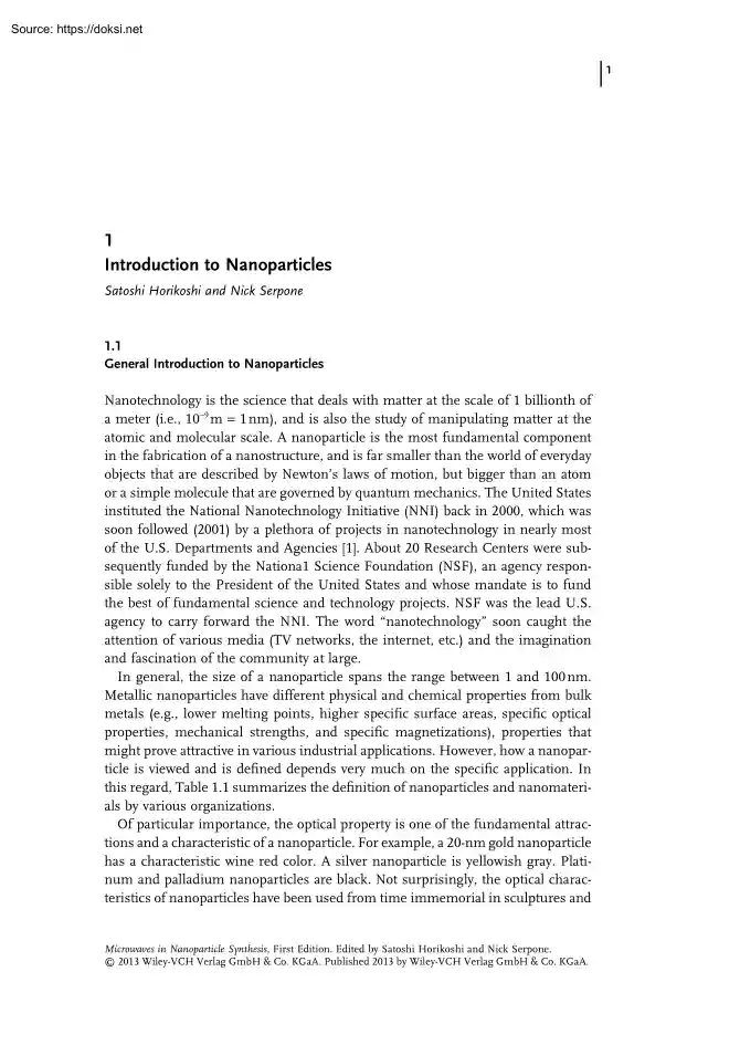
For example, a 20-nm gold nanoparticle has a characteristic wine red color. A silver nanoparticle is yellowish gray Platinum and palladium nanoparticles are black Not surprisingly, the optical characteristics of nanoparticles have been used from time immemorial in sculptures and Microwaves in Nanoparticle Synthesis, First Edition. Edited by Satoshi Horikoshi and Nick Serpone 2013 Wiley-VCH Verlag GmbH & Co. KGaA Published 2013 by Wiley-VCH Verlag GmbH & Co KGaA 2 1 Introduction to Nanoparticles Definitions of nanoparticles and nanomaterials by various organizations: International Organization for Standardization (ISO), American Society of Testing and Materials (ASTM), National Institute of Occupational Safety and Health (NIOSH), Scientific Committee on Consumer Products (SCCP), British Standards Institution (BSI), and Bundesanstalt für Arbeitsschutz und Arbeitsmedizin (BAuA). Table 1.1 Nanoparticle Nanomaterial ISO A particle spanning 1–100 nm (diameter) –
ASTM An ultrafine particle whose length in 2 or 3 places is 1–100 nm – NIOSH A particle with diameter between 1 and 100 nm, or a fiber spanning the range 1–100 nm. – SCCP At least one side is in the nanoscale range. Material for which at least one side or internal structure is in the nanoscale BSI All the fields or diameters are in the nanoscale range. Material for which at least one side or internal structure is in the nanoscale BAuA All the fields or diameters are in the nanoscale range. Material consisting of a nanostructure or a nanosubstance (a) (b) Figure 1.1 Photographs of the famous Lycurgus cup which displays a different color depending on whether it is illuminated externally (a) or internally (b). For details, consult the website of the British Museum [2]. paintings even before the 4th century AD. The most famous example is the Lycurgus cup (fourth century AD) illustrated in Figure 1.1 This extraordinary cup is the only complete historic example
of a very special type of glass, known as dichroic glass, that changes color when held up to the light. The opaque green cup turns to a glowing translucent red when light is shone through it internally (i.e, light is incident on the cup at 90° to the viewing direction) Analysis of the glass revealed that it contains a very small quantity of tiny 1.1 General Introduction to Nanoparticles (∼70 nm) metal crystals of Ag and Au in an approximate molar ratio of 14 : 1, which give it these unusual optical properties. It is the presence of these nanocrystals that gives the Lycurgus Cup its special color display. The reader can marvel at the cup now in the British Museum [2]. Until the Middle Ages, the reputation of soluble gold was based mostly on its fabulous curative powers of various diseases, for example, heart and venereal diseases, dysentery, epilepsy, and tumors; it was also used in the diagnosis of syphilis. The history of the nanoparticle from ancient times to the Middle Ages
has been summarized by Daniel and Astruc [3]. The first book on colloidal gold was published in 1618 by the philosopher and medical doctor Francisci Antonii. This book includes considerable information on the formation of colloidal gold sols and their medical uses, including successful practical cases. The book noted that soluble gold appeared around the fifth or fourth century B.C in Egypt and China. On the other hand, industrial manufacturing of stained glass with colloidal particles was established by Kunckel in the seventeenth century (1676). He also published a book whose Chapter 7 was concerned with “drinkable gold that contains metallic gold in a neutral, slightly pink solution that exerts curative properties for several diseases” [4]. He concluded that gold must be present in aqueous gold solutions to a degree of contamination such that it is not visible to the human eye. A colorant in glasses, that is, the “Purple of Cassius”, was a colloid resulting from the
presence of gold particles and tin dioxide and was highly popular in the seventeenth century. A complete treatise on colloidal gold was published in 1718 by Helcher [5]. In the treatise, this philosopher and doctor stated that the use of boiled starch in its drinkable gold preparation noticeably enhanced its stability. These ideas were common in the eighteenth century, as indicated in a French chemical dictionary dated 1769 [6], under the heading “or potable” it was said that drinkable gold contained gold in its elementary form, albeit under extreme sub-division suspended in a liquid. In 1794, Fuhlame reported in a book that she had dyed silk with colloidal gold [7]. In 1818, Jeremias Benjamin Richters suggested an explanation for the differences in color shown by various preparations of drinkable pink or purple gold solutions in that these solutions contained gold in the finest degree of subdivision, whereas yellow solutions were found when the fine particles had aggregated. In
1857, in a well-known publication, Michael Faraday [8] reported the formation of deep red solutions of colloidal gold by reduction of an aqueous solution of chloroaurate (AuCl4−) by phosphorus in CS2 (a two-phase system). He also investigated the optical properties of thin films prepared from dried colloidal solutions and observed reversible color changes of the films upon mechanical compression (from bluish-purple to green). Since that pioneering work, thousands of scientific papers have been published on the synthesis, modification, properties, and assembly of metal nanoparticles, using a wide variety of solvents and other substrates. Nanotechnology is easily evident in various old churches. A well-known application of early nanotechnology is the ruby red color that was used for stained glass windows during the Middle Ages. Beautiful examples of these applications can be found in glass windows of many Gothic European cathedrals, among which the 3 4 1 Introduction to
Nanoparticles Red: Ag (~100 nm, Triangle) Yellow: Au (~100 nm, Spheres) Green: Au (~50 nm, Spheres) Light blue: Ag (~90 nm, Spheres) Blue: Ag (~40 nm, Spheres) Figure 1.2 Rosace nord stained glass in the Cathédrale Notre-Dame de Chartres (France), color changes depend on the size and shape of gold and silver nanoparticle. From ref. [9] León Cathedral (Spain) represents one of these unique masterpieces, located on the medieval French pilgrimage path to Santiago de Compostela (Spain); its impressive 2000 m2 colored windows offer a unique view that certainly warrants a visit. Of course, the medieval artisans were unaware that they were using nanotechnology They just knew that a particular process produced a beautiful effect For example, the stained glass of a wonderful rose can be seen at the world heritage Cathédrale Notre-Dame de Chartres in France. The stained glass made in medieval times is displayed in Figure 1.2 Later chemistry clarified the reasons behind the generation of
the color. These vivid colors were controlled by the size and the form (or shape) of the nanoparticles of gold and silver. The relation between particles and their associated colors has been discussed recently by Jin and coworkers [9]. In an article of 22 February 2005, the New York Times [10] summarized the relationship between the color of stained glass and the size/shape of the nanoparticles (see Figure 1.3) After several decades, the ingredients present in the stained glass (colored glass) of various churches were clarified subsequent to the development of analytical instruments. People without professional expertise in nanotechnology are also increasingly contributing to the technology. An outline of the historical background in connection with nanoparticles (nanotechnology) is summarized in Table 1.2 The current technology that deals with nanoparticles, or simply nanotechnology, began from the special optical phenomenon and the establishment of a theory to describe the various
physical phenomena that were followed subsequent to the development of analytical instruments. This continues as we speak, with various nanostructures being proposed and discovered, and their applications described. 1.1 General Introduction to Nanoparticles The First Nanotechnologists Ancient stained-glass makers knew that by putting varying, tiny amounts of gold and silver in the glass, they could preduce the red and yellow found in stained-glass windows. Similarly, today’s scientists and engineers have found that it takes only small amounts of a nanoparticle, precisely placed, to change a material’s physical properties. Gold particles in glass Size*: 25 nm Shape: sphere Color reflected: Silver particles in glass Size*: 100 nm Shape: sphere Color reflected: 100 nanometers = 200 nm 0.0001 millimeter Had medieval artists been able to control the size and shape of the nanoparticles, they would have been able to use the two metals to produce other colors. Examples: Size*: 50 nm
Size*: 40 nm Shape: sphere Shape: sphere Color reflected: Color reflected: Size*: 100 nm Shape: sphere Color reflected: Size*: 100 nm Shape: sphere Color reflected: *Approximate Figure 1.3 Comparison of the effect of size and shape of nanoparticles on the coloring of stained glass (Stained Glass Museum, Great Britain); see ref. [10] Industrial production of nanomaterials saw its origins in the twentieth century. For example, nanoparticles of carbon black (tire soot) have been used in the fabrication of rubber tires of automobiles from the beginning of the twentieth century. Pigments such as SiO2 and TiO2 have been prepared by a high-temperature combustion method. Since the 1970s, the innovative development of nanoparticles is due to a combination of theory and experiments in the fields of physics, chemistry, materials science, and biosciences. Specific phenomena (chemical properties and physical properties), other than the optical property of a nanoparticle, have led to new
possibilities in various fields. Applications of nanoparticles in various fields require an inexpensive and simple process of synthesizing high quality shapednanoparticles. In this regard, recent years have witnessed significant research being done in the use of microwave radiation in nanoparticle syntheses. 5 6 Table 1.2 1 Introduction to Nanoparticles Chronological table of nanotechnology. Year Remarks Country/people 1200–1300 BC Discovery of soluble gold Egypt and China 290–325 AD Lycurgus cup Alexandria or Rome 1618 First book on colloidal gold F. Antonii 1676 Book published on drinkable gold that contains metallic gold in neutral media J. von Löwenstern-Kunckel (Germany) 1718 Publication of a complete treatise on colloidal gold Hans Heinrich Helcher 1857 Synthesis of colloidal gold M. Faraday (The Royal Institution of Great Britain) 1902 Surface plasmon resonance (SPR) R. W Wood (Johns Hopkins University, USA) 1908 Scattering and absorption
of electromagnetic fields by a nanosphere G. Mie (University of Göttingen, Germany) 1931 Transmission electron microscope (TEM) M. Knoll and E Ruska (Technical University of Berlin, Germany) 1937 Scanning electron microscope (SEM) M. von Ardenne (Forschungslaboratorium für Elektronenphysik, Germany) 1959 Feynman’s Lecture on “There’s Plenty of Room at the Bottom” R. P Feynman (California Institute of Technology, Pasadena, CA,USA) 1960 Microelectromechanical systems (MEMS) I. Igarashi (Toyota Central R&D Labs, Japan) 1960 Successful oscillation of a laser T. H Maiman (Hughes Research Laboratories, USA) 1962 The Kubo effect R. Kubo (University of Tokyo, Japan) 1965 Moore’s Law G. Moore (Fairchild Semiconductor Inc, USA) 1969 The Honda–Fujishima effect A. Fujishima and K Honda (University of Tokyo, Japan) 1972 Amorphous heterostructure photodiode created with bottom-up process E. Maruyama (Hitachi Co Ltd, Japan) 1974 Concept of
nanotechnology proposed N. Taniguchi (Tokyo University of Science, Japan) 1.1 General Introduction to Nanoparticles 7 Table 1.2 (Continued ) Year Remarks Country/people 1976 Carbon nanofiber M. Endo (Shinshu University, Japan) 1976 Amorphous silicon solar cells D. E Carlson and C R Wronski (RCA, USA) 1980 Quantum hall effect (Nobel Prize) K. von Klitzing (University of Würzburg, Germany) 1982 Scanning tunneling microscope (STM) (Nobel Prize) G. Binnig and H Rohrer (IBM Zurich Research Lab., Switzerland) 1986 Atomic force microscope (AFM) G. Binnig (IBM Zurich Research Lab, Switzerland) 1986 Three-dimensional space manipulation of atoms demonstrated (Nobel Prize) S. Chu (Bell Lab, USA) 1987 Gold nanoparticle catalysis M. Haruta (Industrial Research Institute of Osaka, Japan) 1990 Atoms controlled with scanning tunneling microscope (STM) D. M Eigler (IBM, USA) 1991 Carbon nanotubes discovered S. Iijima (NEC Co, Japan) 1992 Japan’s National
Project on Ultimate Manipulation of Atoms and Molecules begins 1995 Nano-imprinting S. Y Chou (University of Minnesota, USA) 1996 Nano sheets T. Sasaki (National Institute for Research in Inorganic Materials, Japan) 2000 National Nanotechnology Initiative (NNI), USA 2003 21st Century Nanotechnology Research and Development Act, USA 2005 Nanosciences and Nanotechnologies: An action plan, Europe Synthesis of nanoparticles using microwave heating has been on the increase in recent years. Fabrication of high quality nanoparticles can be achieved by simple operations compared with the more conventional nanoparticle synthetic methods. This chapter describes the various features and provides examples of the use of microwaves in nanoparticle synthesis. Moreover, in order to clarify the feature (or features) of the microwave method, a general description of the nanoparticle is also included. 1 Introduction to Nanoparticles 8 1.2 Methods of Nanoparticle Synthesis Various
preparation techniques for nanoparticles (nanomaterials) are summarized in Figure 1.4 Two approaches have been known in the preparation of ultrafine particles from ancient times. The first is the breakdown (top-down) method by which an external force is applied to a solid that leads to its break-up into smaller particles. The second is the build-up (bottom-up) method that produces nanoparticles starting from atoms of gas or liquids based on atomic transformations or molecular condensations. The top-down method is the method of breaking up a solid substance; it can be sub-divided into dry and wet grinding. A characteristic of particles in grain refining processes is that their surface energy increases, which causes the aggregation of particles to increase also. In the dry grinding method the solid substance is ground as a result of a shock, a compression, or by friction, using such popular methods as a jet mill, a hammer mill, a shearing mill, a roller mill, a shock shearing mill, a
ball mill, and a tumbling mill. Since condensation of small particles also takes place simultaneously with pulverization, it is difficult to obtain particle sizes of less than 3 μm by grain refining. On the other hand, wet grinding of a solid substrate is carried out using a tumbling ball mill, or a vibratory ball mill, a planetary ball mill, a centrifugal fluid mill, an agitating beads mill, a flow conduit beads mill, Grinding system Breakdown (top-down) Solid phase method Dry Wet grinding system Mechanochemical method (Mills and Ultrasonic wave) Mechanical alloying method Solid phase method Chemical method Physical method Grain refining of a substance Chemical vapor deposition (CVD: flame, plasma, laser, electric furnace) Thermal decomposition method Physical vapor deposition (PVD) Buildup (bottom-up) Liquid/Liquid method Liquid phase method Sedimentation method Plasma Induced heating Flame hydrolysis Electron beam Laser Molecular beam epitaxy Chemical reduction method
Indirect reduction method Spray drying process Spray pyrolysis process Solvothermal synthesis Supercritical Polyol Organic acid Sodium borohydride Sugar Photoreaction Gamma ray Ultrasonic wave Liquid plasma Sol-gel/Gel-sol co-Precipitation Alkaline precipitation Hydrolysis Colloidal chemistry Figure 1.4 Typical synthetic methods for nanoparticles for the top-down and bottom-up approaches. 1.2 Methods of Nanoparticle Synthesis an annular gap beads mill, or a wet jet mill. Compared with the dry method, the wet process is suitable for preventing the condensation of the nanoparticles so formed, and thus it is possible to obtain highly dispersed nanoparticles. Other than the above, the mechanochemical method and the mechanical alloying method are also known top-down methods. The bottom-up approach is roughly divided into gaseous phase methods and liquid phase methods. For the former, the chemical vapor deposition method (CVD) involves a chemical reaction, whereas the physical vapor
deposition method (PVD) uses cooling of the evaporated material. Although the gaseous phase methods minimize the occurrence of organic impurities in the particles compared to the liquid phase methods, they necessitate the use of complicated vacuum equipment whose disadvantages are the high costs involved and low productivity. The CVD procedure can produce ultrafine particles of less than 1 μm by the chemical reaction occurring in the gaseous phase. The manufacture of nanoparticles of 10 to 100 nm is possible by careful control of the reaction. Performing the high temperature chemical reaction in the CVD method requires heat sources such as a chemical flame, a plasma process, a laser, or an electric furnace. In the PVD method, the solid material or liquid material is evaporated and the resulting vapor is then cooled rapidly, yielding the desired nanoparticles. To achieve evaporation of the materials one can use an arc discharge method. The simple thermal decomposition method has been
particularly fruitful in the production of metal oxide or other types of particles and has been used extensively as a preferred synthetic method in the industrial world. For many years, liquid phase methods have been the major preparation methods of nanoparticles; they can be sub-divided into liquid/liquid methods, and sedimentation methods. Chemical reduction of metal ions is a typical example of a liquid/ liquid method, whose principal advantage is the facile fabrication of particles of various shapes, such as nanorods, nanowires, nanoprisms, nanoplates, and hollow nanoparticles. With the chemical reduction method it is possible to fine-tune the form (shape) and size of the nanoparticles by changing the reducing agent, the dispersing agent, the reaction time and the temperature. The chemical reduction method carries out chemical reduction of the metal ions to their 0 oxidation states (i.e, Mn+ M0); the process uses non-complicated equipment or instruments, and can yield large
quantities of nanoparticles at a low cost in a short time. Of particular interest in this regard is the use of microwave radiation as the heat source that can produce high quality nanoparticles in a short time period. Besides the chemical reduction method which adds a reducing agent (direct reduction method), other reduction methods are known, such as photoreduction using gamma rays, ultrasonic waves, and liquid plasma which can be used to prepare nanoparticles. These methods that do not use a chemical reducing substance have the attractive feature that no extraneous impurities are added to the nanoparticles. Other than these methods, spray drying, spray pyrolysis, solvothermal synthesis, and the supercritical method are also known. The general technique in the sedimentation method is a sol–gel process, which has been used extensively for the fabrication of metal oxide nanoparticles. This 9 10 1 Introduction to Nanoparticles procedure transforms a solution of a metal alkoxide
into a sol by hydrolysis, followed by polycondensation to a gel. Several books are available that provide details of the sol–gel process (see e.g, [11]) The wet process (liquid phase method) guarantees a high dispersivity of nanoparticles compared to the dry method However, if the resulting nanoparticles are dried, aggregation of the particles soon follows. In this case, re-dispersion can be carried out according to the process used in the solid phase method. Although various techniques have been summarized in Figure 1.4, there are some features to consider that are common to all the methods. That is, the synthesis of nanoparticles requires the use of a device or process that fulfills the following conditions: • control of particle size, size distribution, shape, crystal structure and composition distribution • improvement of the purity of nanoparticles (lower impurities) • control of aggregation • stabilization of physical properties, structures and reactants • higher
reproducibility • higher mass production, scale-up and lower costs 1.3 Surface Plasmon Resonance and Coloring The physical phenomenon of surface plasmon resonance (SPR) was reported long ago by Wood who could detect sub-monomolecular coverage [12]. Not only did Wood discover the plasmon resonance phenomenon, but also found that it changed with the composition of the liquid in touch with the metal surface. Although he speculated on how the light, grating and the metal interacted with each other, a clear rationalization of the phenomenon was not provided. He observed a pattern of “anomalous” dark and light bands in the refracted light when he shone polarized light on a mirror with a diffraction grating on its surface. The first theoretical treatment of these anomalies was put forward by Rayleigh in 1907 [13]. Rayleigh’s “dynamical theory of the grating” was based on an expansion of the scattered electromagnetic field in terms of outgoing waves only With this assumption,
he found that the scattered field was singular at wavelengths for which one of the spectral orders emerged from the grating at the grazing angle. He then observed that these wavelengths, which have come to be called the Rayleigh wavelengths, λR, correspond to the Wood anomalies. Further refinements were made by Fano [14], but a complete explanation of the phenomenon was not possible until 1968 when Otto [15], and in the same year Kretschmann and Raether [16], reported the excitation of the surface plasmon band. Surface plasmon resonance has also been similarly researched in solid state physics in recent years in application studies, especially in such applied research as biosensing, solar cells, and super high-density recording. Details on surface plasmon 1.3 Surface Plasmon Resonance and Coloring resonance from the point of view of solid state physics have been given by Schasfoort and Tudos [17]. In this section we present a simple outline of the relation between surface
plasmon resonance and the color of nanoparticles. In solid state physics, the plasmon represents the collective oscillation of a free charge in a metal, and may be considered as a kind of plasma wave. The positive electrical charge in the metal is fixed and the free electron is free to move around it. An applied external electric field, as from a light source, causes the free electrons at the surface of the metal to vibrate collectively, giving rise to surface plasmons. Since electrons are also particles with an electric charge, when they vibrate they also generate an electric field, and when the electric field from the vibration of free electrons and the applied external electric field (e.g, electromagnetic waves) resonate the resulting phenomenon is referred to as a surface plasmon resonance that takes place at the surface of the metal. However, if light irradiates a solution that contains dispersed metal nanoparticles smaller than the wavelength of light, then depending on the
electric field of light, the deviation produces a free electron at the surface of the metal. As a result, the weak or thick portions of the electric field appear on the nanoparticle surface (Figure 1.5) and can be considered as a kind of polarization. Such localized plasmon resonance is called localized surface plasmon resonance (LSPR). The LSPR is typically concentrated in a very narrow region on the surface of a nanoparticle. The electric field distribution on the nanoparticle surface caused by LSPR can be visualized using an electromagnetic field analysis software with a finite element method (Comsol Multiphysics 4.2a) The LSPR distribution on the surface of a 20-nm (diameter) Au nanoparticle is shown in Figure 1.6a When visible light at 520 nm, which corresponds to the maximum position of the LSPR band in the Au nanoparticle, is used to irradiate the nanoparticle, the electric field generated is concentrated on the right and left side of the Au nanoparticle, perpendicular to
the incident light direction. On the other hand, the electric field generated in two adjacent Au nanoparticles is concentrated within the gap between the two particles. Figure 16b illustrates two particles with a 4-nm gap, while Figure - - - + - - - + - - - + E-field + + + - - - Time Figure 1.5 Mechanism of a localized surface plasmon resonance. 11 12 (a) 1 Introduction to Nanoparticles (b) (c) high low Figure 1.6 Images of the electric field distribution on the Au nanoparticle surface (20 nm diameter) under visible light irradiation visualized with Comsol Multiphysics 4.2a: (a) single Au nanoparticle, (b) two Au nanoparticles with 4 nm gap, and (c) two Au nanoparticles with 1 nm gap. 1.6c displays two particles separated by a gap of 1 nm As the gap becomes narrower and narrower, the density of the generated electric field gets bigger and bigger. The wavelength corresponding to the LSPR depends on the kind of metal, the shape of the metal nanoparticle, and the
extent of aggregation of the metallic nanoparticles. Moreover, the surface plasma vibration also changes with the dielectric constant and the quality of the carrier fluid The plasma oscillations in the metal occur mainly in the ultraviolet (UV) region. However, in the case of Au, Ag, and Cu, the plasma shifts nearer to the visible light domain with the band due to electrons in the s atomic orbitals. For example, the wavelength of the surface plasmon resonance band maximum of a spherical Au nanoparticle is 520–550 nm. If a colloidal Au nanoparticle solution is now irradiated with visible light at these wavelengths (520–550 nm), the visible light corresponding to the green color is absorbed and the particles now display a red purple color, which is the complementary color to green. In a colloidal Ag nanoparticle solution which has a plasmon resonance band maximum near 400 nm, the blue color of the visible light is absorbed and the Ag particles now take on a yellow color, the
complementary color to blue. 1.4 Control of Size, Shape, and Structure 1.41 Size Control of Nanoparticles The physical and chemical properties of nanomaterials depend not only on their composition but also on the particle size [18] and shape [19]. Accordingly, a high quality synthesis protocol must first of all provide control over particle size and shape. For example, if the diameter of an Au nanosphere is made to increase, the surface plasmon resonance will be gradually shifted from 530 nm to the longer wavelength side (see Figure 1.7) [20] Thus, if nanoparticles differ in size, their optical characteristics will also change significantly. 1.4 Control of Size, Shape, and Structure Absorbance 1.0 0.8 0.6 0.4 0.2 0.0 400 Diameter/nm 9 22 48 99 500 600 700 Wavelength (nm) Figure 1.7 Visible-light spectra of Au nanospheres with various particle sizes From ref [20] Copyright 2006 by the American Chemical Society. In optical applications of nanoparticles, simplification of
the size distribution of the particles becomes a very important factor. Therefore, it is important to fabricate nanoparticles with a single target size in mind. Generally, in order to prepare monodispersed nanoparticles, it is imperative that the nanoparticles grow very slowly after the rapid generation of the seed particles [21]. If the size of the nanoparticles decreases (i.e, increase in specific surface area), then the increase in the surface energy of such nanoparticles will facilitate their aggregation. Consequently, after their growth to the desired optimal size, it will be necessary to stabilize the particulate surface by addition of a dispersing agent. The historical use of dispersing agents in nanoparticle syntheses is not new; for example, Ag colloids protected by citrate were reported by Lea way back in 1889 [22]. However, where the concentration of nanoparticles is unusually high, the decentralized stabilization will fall, because the protective action of the organic
substrate (citrate) is no longer strong enough to prevent aggregation. Thus, several studies of dispersing agents that maintain a high dispersivity of the nanoparticles, and also at various concentrations, have been reported. According to the hard and soft acids and bases (HSAB) rule [23], Ag+, Au+, Pd2+, Pt2+ are classified as soft acids in the Lewis sense (SA), and substrates possessing the thiol (R–SH) and the phospine (P–R3) functional groups, classified as soft bases, have proven to be suitable dispersing agents [24]. Early research that examined organic thiol molecules as possible dispersing agents was reported by Brust and coworkers [25]. As shown in Figure 18, if 1-dodecanethiol is used as the dispersing agent in Au nanoparticle synthesis the 1-dodecanethiol molecule can form a monomolecular layer on the Au nanoparticle surface, and firmly stabilize the dispersed Au nanoparticles. This particular paper has been the third most cited article in the journal Chemical
Communications ever since 1965 13 1 Introduction to Nanoparticles 14 HS SH M HS M+ + + SH M SH M M + + HS HS M HS M HS SH M HS S S S S S HS M M SH HS HS HS HS S S S M S S S S S S S S Agglomeration Reduction Figure 1.8 Mechanism for the capping of metal nanoparticles with 1-dodecanethiol From ref. [26] Copyright 1994 by the Royal Society of Chemistry (a) (b) (c) (d) (e) (f) Figure 1.9 Typical group diagram of a nanoparticle; (a) Random structure; (b) fractal structure (c) structural alignment; (d) close-packed structure; (e) ordered structure (dispersion); (f) ordered structure (dense). From ref [27] [26], and so can easily be said to have had a significant impact in the chemistry field. Moreover, an increase in the size of the nanoparticles can be achieved by the change in alkyl chain length from 1-dodecanethiol to alkyl chains of octane, decane and hexadecane, as well as with a decrease in steric hindrance. For this reason, the 1-dodecanethiol
dispersing agent is also used to control the particle size. Development of polymers as the dispersing agents has also been studied. In this case, the protection capability is determined by the affinity of the nanoparticle surface and by the molecular weight of the polymer. It is important to realize that the physical properties of a nanoparticle can change with the aggregation ratio, even though the colloidal solution may contain nanoparticles of identical size [27]. The images and the characteristics of the state of aggregation of nanoparticles are depicted in Figure 1.9 In the dispersed random structure shown in Figure 1.9a, the dynamical physical properties and the optical properties are significant. On the other hand, the electronic properties are displayed by the fractal structure shown in Figure 19b, and ion and electronic transport properties appear in the structure orientation of Figure 1.9c The optical properties appear in the close-packed structure of the nanoparticles
(Figure 1.9d), whereas the discrete structures or otherwise orderly structures of Figure 1.9e and f display dynamical physical properties, magnetism, optical, and electronic properties. Methods to separate out particles of a given target size from a colloidal solution which contains nanoparticles of various sizes are known. They are (i) separation 1.4 Control of Size, Shape, and Structure by precipitation, (ii) centrifugal separation, (iii) gel filtration column, and (iv) gel electrophoresis. As a feature of each screening method, the precipitation separation is suitable for a large distribution of colloid nanoparticles in the solution The centrifugal separation and the gel filtration column are well suited for solutions of colloidal nanoparticles with a narrow size distribution. Gel electrophoresis is a suitable method to separate nanoparticles taking advantage of the difference in charge density of the particles, and is suitable for separating particles with a small cluster
size. In fact, a combination of these various methods might prove advantageous However, a problem with sorting the various sized nanoparticles using these methods is that only a fraction of the nanoparticles of a given size may be collected, and then only in small quantities. The digestive ripening method and high temperature melting technique have been proposed to resolve this problem [28]. 1.42 Shape Control of Nanoparticles The shape of nanoparticles is an important factor that determines the nature of the surface plasmon resonance band just as the size of the nanoparticles did (see Figure 1.7) Absorption spectra in the visible spectral region of various Au rodshaped nanoparticles (ie, nanorods) with changes in the aspect ratio (length of long side and short side) are shown in Figure 1.10 [29] The diameters of the Au nanorods espousing a pillar form and used in this experiment ranged from 5 to 20 nm and the lengths from 20 to 150 nm. It is worth noting that the change in Figure
1.10 Visible-light spectra of Au rod-shaped nanoparticles with various aspect ratios (long side to short side in the rod-shaped nanoparticle). From ref [29] Copyright 2006 by the American Chemical Society. 15 16 1 Introduction to Nanoparticles the ratio of a nanorod is related to the size ratio of a crystal face. An increase in the size ratio (aspect ratio) shifts the maximal absorption band to longer wavelengths. Therefore, the physical composition of the nanorods can easily change their spectroscopic features, such that various studies have been required to understand these characteristics. The preparation of Au nanorods using surfactants has been reported by Yu and coworkers [29]. Gold nanorods were synthesized using an Au anode under ultrasonic irradiation with a template consisting of the cationic surfactant hexadecyltrimethylammonium bromide (CTAB) Au exfoliates as a cluster from the electrode and is molded into the shape of a rod through the interaction with the CTAB
micelle (at concentrations above the cmc). In the growth mechanism of nanorods, the CTAB dispersing agent is selectively adsorbed onto the {100} and {110} crystal faces of the Au nanoparticles. For this reason, the {111} crystal face grows and a rod-like metal nanoparticle is generated as a result. The use of CTAB as the dispersing agent subsequently quickly led to reports on nanoparticle research [30, 31]. Nanoparticles of various forms and shapes have been prepared using the adsorption characteristics of a dispersing agent. Chen and coworkers reported an unusual composition of branched Au nanoparticles (see Figure 1.11) using high concentrations of CTAB [32]. Evidently, the molecular association of a surfactant as a dispersing agent determines the various shape features of metallic nanoparticles. The physical aspects of Au nanorods prepared using a hard template, such as mesoporous alumina, are similar to those when using a soft template like CTAB. In an early report that made use of
a hard template, the Au nanorods were (a) (b) (110) [101] [011] 0.144 nm 0.144 nm (111) (011) (c) 10 nm (d) (e) [110] (101) (f) Figure 1.11 (a) TEM image of a regular tripod nanocrystal and (b) high-resolution image of the pod end as marked by a white frame in panel (a); (c) diagram showing the crystal planes and pod directions. The lower (g) row of panels exhibits the particles developed at various stages: (d) embryo of a triangular shape, (e) monopod, (f) V-shaped bipod, and (g) Y-shaped tripod. From ref [32] Copyright 2003 by the American Chemical Society. 1.4 Control of Size, Shape, and Structure synthesized in the inner fine pores of mesoporous alumina [33]. In the initial stage, the nanosize porous alumina electrode is produced and the metal is then electrochemically deposited sequentially in the fine pores, which provide a firm mold; the diameter of the short axis of the Au nanorod which grows inside the fine pores is regulated by the size of the pores.
Subsequently, the alumina mold is dissolved and removed; the so-formed Au nanorods are then taken out of the template. An interesting feature of the above method is the fabrication of nanorods of multiple layers of different metals such as Au–Ag–Au. Therefore, a nanoparticle with various features can be synthesized. As for the plural layer-type nanorod, applied research can lead to a nanosize system that might be considered a nanosized bar code [34]. 1.43 Structure Control of Nanoparticles Nanoparticles that are composed of two or more metals differ in their catalytic, magnetic, and optical characteristics from nanoparticles that consist of a single metal. Such nanoparticles can be sub-divided into three kinds of structures: (i) the alloy structure that exists randomly in a crystal (Figure 1.12a); (ii) the core–shell structure in which the metal at the center differs from the peripheral metal (Figure 1.12b); and (iii) the twinned hemisphere structure wherein two sorts of
hemispheres are joined. The latter heterojunction structure facilitates phase separation (Figure 1.12c) Nanostructures consisting of complex metal nanoparticles tend to hide the various new features. The core–shell structure is comparatively easy to fabricate in complex metal nanoparticles with effective functional control, which has led to several studies and reports in the literature. For instance, although the color of an Au nanoparticle liquid dispersion is purplish red (the purple of Cassius) and that of an Ag nanoparticle liquid dispersion appears yellow, whenever Au forms the core and Ag the shell the structure then takes an orange color. Moreover, if a structured matter (a) (b) (c) Figure 1.12 Schematic images of bimetal nanoparticles: alloy structure (a), core–shell structure (b), and heterojunction structure (c) of complex metal nanoparticles. 17 18 1 Introduction to Nanoparticles Figure 1.13 SEM image of gold nanotubes that had been broken through sonication to
show their cross-sections. The gold nanotubes were prepared by reacting silver nanowires with an aqueous HAuCl4 solution. From ref [37] Copyright 2003 by the American Chemical Society has magnetic properties, such as magnetite nanoparticles, then the magnetic metal particles could be used to form the structure’s core, such that the structure will now be embodied with both magnetic and optical characteristics. Synthetic methods of preparing core–shell nanoparticles are roughly divided into two categories: (i) involving a simultaneous reduction reaction and (ii) involving a sequential one-electron reduction reaction. As an example of the simultaneous reduction reaction, consider the core being made up of Pt nanoparticles and the shell composed of Pd nanoparticles [35]. A unique method that uses differences in the oxidation potentials of Ag and Au has also been reported [36] Here, a silver nanoparticle is added to an HAuCl4 solution, following which an oxidation– reduction reaction
takes place (Eq. 11) wherein gold is deposited on the surface of a Ag nanoparticle yielding the core–shell structure. 3Ag(s) + HAuCl 4 (aq) Au(s) + 3AgCl (aq) + HCl (aq) (1.1) The development of this method has led to the fabrication of Au nanotubes by first making the pentagonal prismatic Ag nanowires to use as the template (Figure 1.13) [37] 1.5 Reducing Agent in Nanoparticle Synthesis Gold hydrosols have been synthesized through reduction of a gold chloride solution under an atmosphere of phosphorus; the method succeeded in controlling the size of Ag nanoparticles [8]. Decades later, Turkevich and coworkers examined the mechanism of metal salt reduction with citric acid [38]. The latter acid has been used widely as a reducing agent to fabricate various metal nanoparticles. The 1.6 Applications of Metallic Nanoparticles reduction of hexachloroplatinic acid with sodium borohydride has also been investigated, together with hydroxylamine hydrochloride, dimethylaminoborane,
sodium citrate, hydrazine hydrate, sodium formate, boranetrimethylamine complex, sodium borohydride and formaldehyde as the reducing agents; the various features of the resulting nanoparticles were examined [39]. More recently, the polyol method using ethylene glycol has become quite popular. Ethylene glycol can be both the reaction solvent and the reducing agent in the synthesis of nanoparticles. What made ethylene glycol attractive was its polar nature, which is useful in dissolving the metal salt and can also play the role of a dispersing agent, and since it has a high boiling point (198 °C) it is suitable for the preparation of the base metal. On the other hand, the disadvantage of this polyol is the high boiling point making removal of the solvent difficult. 1.6 Applications of Metallic Nanoparticles The various characteristics of different nanoparticles relative to bulk metals are summarized below. Optical function: The surface absorption plasmon of Au and Ag can express
various colors by changing the size of the particle, the form or shape of the particle, and the rate of condensation. A new paint that has the durability of an inorganic pigment and the vivid color of an organic substrate can be made. Nanoparticles smaller than the wavelength of light can be used to make highpenetration conductivity materials (there is little absorption, dispersion, and reflection). Catalyst function: Reaction efficiencies can be enhanced since the specific surface area of such nanoparticles is large compared with existing particles; to the extent that the surface terrace is regular at the atomic level, a hyperactive catalyst with high selectivity can be made: for example, Au nanoparticles. Thermal function: When the particle diameter is small (less than 10 nm), the melting point is also lower than a bulk metal. Electronic wiring can be made with nanoparticles that have a low boiling point, for example, a polymer. Electrical function: Since superconductivity
transition temperature rises so that particle diameter is small (less than 1 nm), it can be used to make hightemperature superconductivity material. Mechanical function: Since the mechanical characteristics improve, mechanical strength can be sharply raised by mixing the nanoparticles with metals or ceramics. Magnetic function: The attractive force of a magnetic metal increases on reduction of the particle diameter, such that soft-magnetic materials can be made in the form of an alloy of nanoparticles. Moreover, a permanent magnet can be made 19 20 1 Introduction to Nanoparticles if the nanoparticles are smaller than the magnetic domain made to magnetize. 1.61 Application of Nanoparticles in Paints One of the most interesting aspects of metal nanoparticles is that their optical properties depend strongly upon the particle size and shape. Bulk Au looks yellowish in reflected light, but thin Au films look blue in transmission This characteristic blue color steadily changes to
orange, through several tones of purple and red, as the particle size is reduced down to ∼3 nm. The nanoparticles attracted attention as color materials and the possibility of their use has been examined in various fields. Figure 114 illustrates the photograph of a car to which was applied a “clear colored coating” containing gold nanoparticles on a base coating containing red pearl mica [40]. Spraying with the clear colored coating containing the nanoparticles increased the depth of the red background even more, and since the car is in the shade there is almost no diffuse reflection. The red color becomes a feature of paints containing nanoparticles. Paints that contain nanoparticles cannot be removed as easily as can classical paint. However, because of high costs, paints with nanoparticles are used only in limited applications. Metal nanoparticles have also been used in enamel color paints in pottery. Conventional enamel color has used paints with mixed transition metals in
the pulverization (glass frit) of glass If, instead of transition metal paints, Au nanoparticles were used, then high quality red paint could be made with high transparency. Research into iron oxide nanoparticles in paints has also been carried out. 1.62 Application in Chemical Catalysis Ni, Pd, Ag, and Pt have been used as typical metal catalysts in chemical reactions. However, the dissociative adsorption of hydrogen or oxygen molecules cannot be Figure 1.14 Photograph of a car to which was applied a clear coating containing gold nanoparticles on a red colored base coating. From ref [40] 1.6 Applications of Metallic Nanoparticles carried out on an Au smooth surface and at a temperature of less than 200 °C [41]. Therefore, such a gold material is inactive as a catalyst in hydrogenation and oxidation reactions. However, when Au nanoparticles are used, they work effectively as catalysts, as discovered by Haruta [42]. The ratio of the corner to the edge of an Au nanoparticle of
several nanometers in size becomes large compared with Au particles of larger size. Thus, both the adsorption and the catalytic characteristics of the Au surface increase. In an icosahedron consisting of 2054 Au atoms, the percentage of Au atoms exposed on the surface is 15% in Au nanoparticles of 4.9 nm size (external diameters), whereas the surface exposure of an Au atom reaches 52% in 2.7 nm sized nanoparticles (309 Au atoms) If the number of Au atoms in a nanoparticle was to become even smaller, the number of atoms that constitutes the whole, as well as the electrons, will become limited since the electronic structure of the nanoparticle would then become discontinuous [43]. This state takes on a cluster structure and a quantum size effect shows up in the physical properties. Generally, metals that form clusters of such a small size tend to be unstable to the atmosphere. However, Au clusters are stable and so Au can be used as a catalyst. The catalytic action is rapid as the size
of the Au nanoparticle is small in catalyzed oxidation reactions. For example, in order to oxidize CO with a Pt catalyst, a temperature of not less than 100 °C is needed However, with an Au nanoparticle as the catalyst, reaction can occur even at temperatures below 0 °C (see Figure 1.15) These effects are the result of changes in the so-called surface plasmon resonance [44], which is observed at the frequency at which conduction electrons oscillate in response to the alternating electric field of the incident electromagnetic radiation. However, only metals with free electrons (essentially Au, Ag, Cu, and the alkali metals) possess plasmon resonances in the visible spectral region, which give rise to such intense colors for these metals. Elongated nanoparticles (ellipsoids and nanorods) display two distinct plasmon bands related to transverse and longitudinal electron oscillations. Figure 1.15 Particle dependence of Au catalyst and Pt catalyst in the CO oxidation reaction (TOF:
turnover frequency). 21 22 1 Introduction to Nanoparticles 1.63 Application of Nanoparticles in Micro-wiring Metal nanoparticle paste is used for circuit pattern formation of a printed wired board in the electronic industry [45]. The melting point of metal nanoparticles decreases relative to bulk metals, so that circuit formation impossible on polymer base material is attainable using a conventional electric conduction paste. Furthermore, whenever particles at the nanoscale are used, the wiring width is thin to a nano level. Formation of nanoparticle wiring can use an ink-jet method, a method that is both inexpensive and requires shorter times than vacuum evaporation and photolithographic methods that are typically used. Generally, Au is used to make the metal nanoparticle paste. However, it is expensive, so that substitution of Cu nanoparticles has been proposed. Cu nanoparticles tend to be oxidized so that the process requires the presence of anti-oxidants. 1.64 Application of
Nanoparticles in Medical Treatments Just as the surface plasmon resonance is seen in a metal nanoparticle, an increase in the quantity of nanoparticles raises the scattering intensity. Taking advantage of this feature, the application to specific molecule recognition in a living body tissue is expected (see e.g, refs [46, 47]) For example, by covering the cancer cell surface it becomes possible to distinguish a healthy cell from a cancer cell by the presence of antibodies joined to the Au nanoparticle. Although the Au nanoparticle junction with the antibody is nicely distributed in the healthy cell (Figure 1.16a), when a cancer cell exists the antibodies are concentrated mostly at the Au nanoparticle (Figure 1.16b) The imaging at various wavelengths is performed by a change in the shape of the nanoparticle [48]. Moreover, if a protein and a functional molecule were joined to the Au nanoparticle, it could also be used for imaging cells other than cancer cells. In addition, to the
extent that Au nanorods (a) (b) Figure 1.16 Molecular-specific imaging of cancer cells using Au nanoparticle/anti-EGFR conjugates. (a) Dispersed Au nanoparticle in healthy cells, (b) Concentrated Au nanoparticles about a cancer cell. From ref [48] Copyright 2008 by the American Chemical Society References also display a plasmon resonance in the near-infrared domain, and that such Au nanorods congregate about the circumference of an abnormal cell, it becomes possible to treat cancer using a near-infrared laser. References 1 For details about NNI see the website: www.nanogov 2 For details about the British Museum see the website: http://www. britishmuseum.org/explore/highlight image.aspx?image=k741 jpg&retpage=20945. 3 Daniel, M.-C, and Astruc, D (2004) Chem. Rev, 104, 293–346 4 Kunckel, J. (1676) Ars Vitraria Experimentals oder Vollkommene Glasmacherkunst, Frankfurt, Germany. 5 Helcher, H.H (1718) Aurum Potabile Oder Gold Tinstur, J. Herbord Klossen, Breslau and
Leipzig, Germany. 6 (1769) Dictionaire de Chymie, Lacombe, Paris. 7 Fulhame, M. (1794) An Essay on Combustion with a View to a New Art of Dying and Painting, J. Cooper, London, UK. 8 Faraday, M. (1857) Philos Trans R Soc London, 147, 145–181. 9 Jin, R., Cao, Y, Mirkin, CA, Kelly, KL, Schatz, G.C, and Zheng, JG (2001) Science, 294, 1901–1903. 10 For the details about The New York Times article of February 22, 2005 see: http://www.nytimescom/ imagepages/2005/02/21/ science/20050222 NANO1 GRAPHIC.html 11 See e.g (a) Brinker, CJ and Scherer, G.W (1989) Sol-Gel Science: The Physics and Chemistry of Sol-Gel Processing, Elsevier Science, Amsterdam; (b) Hench, L.L, and West, J.K (1990) Chem Rev, 90, 33–72. 12 (a) Wood, R.W (1902) Proc Phys Soc London, 18, 269–275; (b) Wood, R.W (1902) Philos. Mag, 4, 396–402; Wood, R.W (1912) Philys Mag, 23, 310–317 13 Rayleigh, L. (1907) Proc R Soc London Ser. A, 79, 399–416 14 Fano, U. (1941) J Opt Soc Am, 31, 213–222. 15 Otto, A. (1968) Z
Phys, 216, 398–410 16 Kretschmann, E., and Raether, H (1968) Z. Naturforsch Teil A, 23, 2135–2136 17 see e.g Schasfoort, RBM and Tudos, A.J (2008) Handbook of Surface Plasmon Resonance, The Royal Society of Chemistry Publishing, Cambridge, UK. 18 Henglein, A. (1989) Chem Rev, 89, 1861–1873. 19 Burda, C., Chen, X, Narayanan, R, and El-Sayed, M.A (2005) Chem Rev, 105, 1025–1102. 20 Liz-Marzán, L.M (2006) Langmuir, 22, 32–41. 21 Sugimoto, T. (2000) Fine Particles: Synthesis, Characterization, and Mechanisms of Growth, Surfactant Sci. Series Vol. 92, Marcel Dekker Inc, New York. 22 Lea, M.C (1889) Am J Sci, 37, 476–491. 23 Pearson, R.G (1963) J Am Chem Soc, 85, 3533–3539. 24 Prasad, B.LV, Stoeva, SI, Sorensen, C.M, and Klabunde, KJ (2003) Chem Mater., 15, 935–942 25 Brust, M., Walker, M, Bethell, D, Schiffrin, D.J, and Whyman, R (1994) Chem. Commun, 801–802 26 See http://www.rscorg/Publishing/ Journals/cc/News/ Top40MostCitedArticles.asp 27 Yamaguchi, Y. (2008)
Kagakukougaku, 72, 344–348. 28 Stoeva, S., Klabunde, KJ, Sorensen, C.M, and Dragieva, I (2002) J Am Chem. Soc, 124, 2305–2311 29 Yu, Y.-Y, Chang, S-S, Lee, C-L, and Wang, C.RC (1997) J Phys Chem B, 101, 6661–6664. 30 (a) Jana, N.R, Gearheart, L, and Murphy, C.J (2001) J Phys Chem B, 105, 4065–4067; (b) Jana, N.R, Gearheart, L, 23 24 1 Introduction to Nanoparticles and Murphy, C.J (2001) Chem Mater, 13, 2313–2322. 31 Nikoobakht, B., and El-Sayed, MA (2001) Langmuir, 17, 6368–6374. 32 Chen, S., Wang, ZL, Ballato, J, Foulger, S.H, and Carroll, DL (2003) J Am Chem. Soc, 125, 16186–16187 33 van der Zande, B.MI, Böhmer, MR, Fokkink, L.GJ, and Schöneberger, C (1997) J. Phys Chem B, 101, 852–854 34 Nicewarner-Peña, S.R, Freeman, GP, Reiss, B.D, He, L, Peña, DJ, Walton, I.D, Cromer, R, Keating, CD, and Natan, M.J (2001) Science, 294, 137–141 35 Toshima, N., Yonezawa, T, and Kushihashi, K. (1993) J Chem Soc Faraday Trans., 89, 2537–2543 36 Sun, Y., Mayers, B,
Herricks, T, and Xia, Y. (2003) Nano Lett, 3, 955–960 37 Sun, Y., and Xia, Y (2002) Science, 298, 2176–2179. 38 Turkevich, J., Stevenson, PC, and Hillier, J. (1951) Discuss Faraday Soc, 11, 55–75. 39 Rheenen, P.RV, McKelvy, MJ, and Glaunsinger, W.S (1987) J Solid State Chem., 67, 151–169 40 Iwakoshi, A. (2008) Techno-cosmos, 21, 32–38. 41 Saliba, N., Parker, DH, and Koel, BE (1998) Surf. Sci, 410, 270–282 42 Haruta, M. (2003) Chem Rec, 3, 75–87 43 Haruta, M. (2008) J Vac Soc Jpn, 51, 721–726. 44 Kreibig, U., and Vollmer, M (1995) Optical Properties of Metal Clusters, Springer-Verlag, Berlin. 45 Kawazome, M., Kim, K, Hatamura, M, and Suganuma, K. (2006/2007) Funsai, 50, 27–31. 46 Bendayan, M. (1989) Colloidal Gold, Volume 1: Principles, Methods, and Applications (ed. MA Hayat), Academic press, Inc., London, pp 34–88 (Chapter 3). 47 Wang, L., Li, J, Song, S, Li, D, and Fan, C. (2009) J Phys D Appl Phys, 42, 203001–203012. 48 Jain, P.K, Huang, X, El-Sayed, IH,
and El-Sayed, M.A (2008) Acc Chem Res, 41, 1578–1586
best of fundamental science and technology projects. NSF was the lead US agency to carry forward the NNI. The word “nanotechnology” soon caught the attention of various media (TV networks, the internet, etc.) and the imagination and fascination of the community at large. In general, the size of a nanoparticle spans the range between 1 and 100 nm. Metallic nanoparticles have different physical and chemical properties from bulk metals (e.g, lower melting points, higher specific surface areas, specific optical properties, mechanical strengths, and specific magnetizations), properties that might prove attractive in various industrial applications. However, how a nanoparticle is viewed and is defined depends very much on the specific application In this regard, Table 1.1 summarizes the definition of nanoparticles and nanomaterials by various organizations Of particular importance, the optical property is one of the fundamental attractions and a characteristic of a nanoparticle.
For example, a 20-nm gold nanoparticle has a characteristic wine red color. A silver nanoparticle is yellowish gray Platinum and palladium nanoparticles are black Not surprisingly, the optical characteristics of nanoparticles have been used from time immemorial in sculptures and Microwaves in Nanoparticle Synthesis, First Edition. Edited by Satoshi Horikoshi and Nick Serpone 2013 Wiley-VCH Verlag GmbH & Co. KGaA Published 2013 by Wiley-VCH Verlag GmbH & Co KGaA 2 1 Introduction to Nanoparticles Definitions of nanoparticles and nanomaterials by various organizations: International Organization for Standardization (ISO), American Society of Testing and Materials (ASTM), National Institute of Occupational Safety and Health (NIOSH), Scientific Committee on Consumer Products (SCCP), British Standards Institution (BSI), and Bundesanstalt für Arbeitsschutz und Arbeitsmedizin (BAuA). Table 1.1 Nanoparticle Nanomaterial ISO A particle spanning 1–100 nm (diameter) –
ASTM An ultrafine particle whose length in 2 or 3 places is 1–100 nm – NIOSH A particle with diameter between 1 and 100 nm, or a fiber spanning the range 1–100 nm. – SCCP At least one side is in the nanoscale range. Material for which at least one side or internal structure is in the nanoscale BSI All the fields or diameters are in the nanoscale range. Material for which at least one side or internal structure is in the nanoscale BAuA All the fields or diameters are in the nanoscale range. Material consisting of a nanostructure or a nanosubstance (a) (b) Figure 1.1 Photographs of the famous Lycurgus cup which displays a different color depending on whether it is illuminated externally (a) or internally (b). For details, consult the website of the British Museum [2]. paintings even before the 4th century AD. The most famous example is the Lycurgus cup (fourth century AD) illustrated in Figure 1.1 This extraordinary cup is the only complete historic example
of a very special type of glass, known as dichroic glass, that changes color when held up to the light. The opaque green cup turns to a glowing translucent red when light is shone through it internally (i.e, light is incident on the cup at 90° to the viewing direction) Analysis of the glass revealed that it contains a very small quantity of tiny 1.1 General Introduction to Nanoparticles (∼70 nm) metal crystals of Ag and Au in an approximate molar ratio of 14 : 1, which give it these unusual optical properties. It is the presence of these nanocrystals that gives the Lycurgus Cup its special color display. The reader can marvel at the cup now in the British Museum [2]. Until the Middle Ages, the reputation of soluble gold was based mostly on its fabulous curative powers of various diseases, for example, heart and venereal diseases, dysentery, epilepsy, and tumors; it was also used in the diagnosis of syphilis. The history of the nanoparticle from ancient times to the Middle Ages
has been summarized by Daniel and Astruc [3]. The first book on colloidal gold was published in 1618 by the philosopher and medical doctor Francisci Antonii. This book includes considerable information on the formation of colloidal gold sols and their medical uses, including successful practical cases. The book noted that soluble gold appeared around the fifth or fourth century B.C in Egypt and China. On the other hand, industrial manufacturing of stained glass with colloidal particles was established by Kunckel in the seventeenth century (1676). He also published a book whose Chapter 7 was concerned with “drinkable gold that contains metallic gold in a neutral, slightly pink solution that exerts curative properties for several diseases” [4]. He concluded that gold must be present in aqueous gold solutions to a degree of contamination such that it is not visible to the human eye. A colorant in glasses, that is, the “Purple of Cassius”, was a colloid resulting from the
presence of gold particles and tin dioxide and was highly popular in the seventeenth century. A complete treatise on colloidal gold was published in 1718 by Helcher [5]. In the treatise, this philosopher and doctor stated that the use of boiled starch in its drinkable gold preparation noticeably enhanced its stability. These ideas were common in the eighteenth century, as indicated in a French chemical dictionary dated 1769 [6], under the heading “or potable” it was said that drinkable gold contained gold in its elementary form, albeit under extreme sub-division suspended in a liquid. In 1794, Fuhlame reported in a book that she had dyed silk with colloidal gold [7]. In 1818, Jeremias Benjamin Richters suggested an explanation for the differences in color shown by various preparations of drinkable pink or purple gold solutions in that these solutions contained gold in the finest degree of subdivision, whereas yellow solutions were found when the fine particles had aggregated. In
1857, in a well-known publication, Michael Faraday [8] reported the formation of deep red solutions of colloidal gold by reduction of an aqueous solution of chloroaurate (AuCl4−) by phosphorus in CS2 (a two-phase system). He also investigated the optical properties of thin films prepared from dried colloidal solutions and observed reversible color changes of the films upon mechanical compression (from bluish-purple to green). Since that pioneering work, thousands of scientific papers have been published on the synthesis, modification, properties, and assembly of metal nanoparticles, using a wide variety of solvents and other substrates. Nanotechnology is easily evident in various old churches. A well-known application of early nanotechnology is the ruby red color that was used for stained glass windows during the Middle Ages. Beautiful examples of these applications can be found in glass windows of many Gothic European cathedrals, among which the 3 4 1 Introduction to
Nanoparticles Red: Ag (~100 nm, Triangle) Yellow: Au (~100 nm, Spheres) Green: Au (~50 nm, Spheres) Light blue: Ag (~90 nm, Spheres) Blue: Ag (~40 nm, Spheres) Figure 1.2 Rosace nord stained glass in the Cathédrale Notre-Dame de Chartres (France), color changes depend on the size and shape of gold and silver nanoparticle. From ref. [9] León Cathedral (Spain) represents one of these unique masterpieces, located on the medieval French pilgrimage path to Santiago de Compostela (Spain); its impressive 2000 m2 colored windows offer a unique view that certainly warrants a visit. Of course, the medieval artisans were unaware that they were using nanotechnology They just knew that a particular process produced a beautiful effect For example, the stained glass of a wonderful rose can be seen at the world heritage Cathédrale Notre-Dame de Chartres in France. The stained glass made in medieval times is displayed in Figure 1.2 Later chemistry clarified the reasons behind the generation of
the color. These vivid colors were controlled by the size and the form (or shape) of the nanoparticles of gold and silver. The relation between particles and their associated colors has been discussed recently by Jin and coworkers [9]. In an article of 22 February 2005, the New York Times [10] summarized the relationship between the color of stained glass and the size/shape of the nanoparticles (see Figure 1.3) After several decades, the ingredients present in the stained glass (colored glass) of various churches were clarified subsequent to the development of analytical instruments. People without professional expertise in nanotechnology are also increasingly contributing to the technology. An outline of the historical background in connection with nanoparticles (nanotechnology) is summarized in Table 1.2 The current technology that deals with nanoparticles, or simply nanotechnology, began from the special optical phenomenon and the establishment of a theory to describe the various
physical phenomena that were followed subsequent to the development of analytical instruments. This continues as we speak, with various nanostructures being proposed and discovered, and their applications described. 1.1 General Introduction to Nanoparticles The First Nanotechnologists Ancient stained-glass makers knew that by putting varying, tiny amounts of gold and silver in the glass, they could preduce the red and yellow found in stained-glass windows. Similarly, today’s scientists and engineers have found that it takes only small amounts of a nanoparticle, precisely placed, to change a material’s physical properties. Gold particles in glass Size*: 25 nm Shape: sphere Color reflected: Silver particles in glass Size*: 100 nm Shape: sphere Color reflected: 100 nanometers = 200 nm 0.0001 millimeter Had medieval artists been able to control the size and shape of the nanoparticles, they would have been able to use the two metals to produce other colors. Examples: Size*: 50 nm
Size*: 40 nm Shape: sphere Shape: sphere Color reflected: Color reflected: Size*: 100 nm Shape: sphere Color reflected: Size*: 100 nm Shape: sphere Color reflected: *Approximate Figure 1.3 Comparison of the effect of size and shape of nanoparticles on the coloring of stained glass (Stained Glass Museum, Great Britain); see ref. [10] Industrial production of nanomaterials saw its origins in the twentieth century. For example, nanoparticles of carbon black (tire soot) have been used in the fabrication of rubber tires of automobiles from the beginning of the twentieth century. Pigments such as SiO2 and TiO2 have been prepared by a high-temperature combustion method. Since the 1970s, the innovative development of nanoparticles is due to a combination of theory and experiments in the fields of physics, chemistry, materials science, and biosciences. Specific phenomena (chemical properties and physical properties), other than the optical property of a nanoparticle, have led to new
possibilities in various fields. Applications of nanoparticles in various fields require an inexpensive and simple process of synthesizing high quality shapednanoparticles. In this regard, recent years have witnessed significant research being done in the use of microwave radiation in nanoparticle syntheses. 5 6 Table 1.2 1 Introduction to Nanoparticles Chronological table of nanotechnology. Year Remarks Country/people 1200–1300 BC Discovery of soluble gold Egypt and China 290–325 AD Lycurgus cup Alexandria or Rome 1618 First book on colloidal gold F. Antonii 1676 Book published on drinkable gold that contains metallic gold in neutral media J. von Löwenstern-Kunckel (Germany) 1718 Publication of a complete treatise on colloidal gold Hans Heinrich Helcher 1857 Synthesis of colloidal gold M. Faraday (The Royal Institution of Great Britain) 1902 Surface plasmon resonance (SPR) R. W Wood (Johns Hopkins University, USA) 1908 Scattering and absorption
of electromagnetic fields by a nanosphere G. Mie (University of Göttingen, Germany) 1931 Transmission electron microscope (TEM) M. Knoll and E Ruska (Technical University of Berlin, Germany) 1937 Scanning electron microscope (SEM) M. von Ardenne (Forschungslaboratorium für Elektronenphysik, Germany) 1959 Feynman’s Lecture on “There’s Plenty of Room at the Bottom” R. P Feynman (California Institute of Technology, Pasadena, CA,USA) 1960 Microelectromechanical systems (MEMS) I. Igarashi (Toyota Central R&D Labs, Japan) 1960 Successful oscillation of a laser T. H Maiman (Hughes Research Laboratories, USA) 1962 The Kubo effect R. Kubo (University of Tokyo, Japan) 1965 Moore’s Law G. Moore (Fairchild Semiconductor Inc, USA) 1969 The Honda–Fujishima effect A. Fujishima and K Honda (University of Tokyo, Japan) 1972 Amorphous heterostructure photodiode created with bottom-up process E. Maruyama (Hitachi Co Ltd, Japan) 1974 Concept of
nanotechnology proposed N. Taniguchi (Tokyo University of Science, Japan) 1.1 General Introduction to Nanoparticles 7 Table 1.2 (Continued ) Year Remarks Country/people 1976 Carbon nanofiber M. Endo (Shinshu University, Japan) 1976 Amorphous silicon solar cells D. E Carlson and C R Wronski (RCA, USA) 1980 Quantum hall effect (Nobel Prize) K. von Klitzing (University of Würzburg, Germany) 1982 Scanning tunneling microscope (STM) (Nobel Prize) G. Binnig and H Rohrer (IBM Zurich Research Lab., Switzerland) 1986 Atomic force microscope (AFM) G. Binnig (IBM Zurich Research Lab, Switzerland) 1986 Three-dimensional space manipulation of atoms demonstrated (Nobel Prize) S. Chu (Bell Lab, USA) 1987 Gold nanoparticle catalysis M. Haruta (Industrial Research Institute of Osaka, Japan) 1990 Atoms controlled with scanning tunneling microscope (STM) D. M Eigler (IBM, USA) 1991 Carbon nanotubes discovered S. Iijima (NEC Co, Japan) 1992 Japan’s National
Project on Ultimate Manipulation of Atoms and Molecules begins 1995 Nano-imprinting S. Y Chou (University of Minnesota, USA) 1996 Nano sheets T. Sasaki (National Institute for Research in Inorganic Materials, Japan) 2000 National Nanotechnology Initiative (NNI), USA 2003 21st Century Nanotechnology Research and Development Act, USA 2005 Nanosciences and Nanotechnologies: An action plan, Europe Synthesis of nanoparticles using microwave heating has been on the increase in recent years. Fabrication of high quality nanoparticles can be achieved by simple operations compared with the more conventional nanoparticle synthetic methods. This chapter describes the various features and provides examples of the use of microwaves in nanoparticle synthesis. Moreover, in order to clarify the feature (or features) of the microwave method, a general description of the nanoparticle is also included. 1 Introduction to Nanoparticles 8 1.2 Methods of Nanoparticle Synthesis Various
preparation techniques for nanoparticles (nanomaterials) are summarized in Figure 1.4 Two approaches have been known in the preparation of ultrafine particles from ancient times. The first is the breakdown (top-down) method by which an external force is applied to a solid that leads to its break-up into smaller particles. The second is the build-up (bottom-up) method that produces nanoparticles starting from atoms of gas or liquids based on atomic transformations or molecular condensations. The top-down method is the method of breaking up a solid substance; it can be sub-divided into dry and wet grinding. A characteristic of particles in grain refining processes is that their surface energy increases, which causes the aggregation of particles to increase also. In the dry grinding method the solid substance is ground as a result of a shock, a compression, or by friction, using such popular methods as a jet mill, a hammer mill, a shearing mill, a roller mill, a shock shearing mill, a
ball mill, and a tumbling mill. Since condensation of small particles also takes place simultaneously with pulverization, it is difficult to obtain particle sizes of less than 3 μm by grain refining. On the other hand, wet grinding of a solid substrate is carried out using a tumbling ball mill, or a vibratory ball mill, a planetary ball mill, a centrifugal fluid mill, an agitating beads mill, a flow conduit beads mill, Grinding system Breakdown (top-down) Solid phase method Dry Wet grinding system Mechanochemical method (Mills and Ultrasonic wave) Mechanical alloying method Solid phase method Chemical method Physical method Grain refining of a substance Chemical vapor deposition (CVD: flame, plasma, laser, electric furnace) Thermal decomposition method Physical vapor deposition (PVD) Buildup (bottom-up) Liquid/Liquid method Liquid phase method Sedimentation method Plasma Induced heating Flame hydrolysis Electron beam Laser Molecular beam epitaxy Chemical reduction method
Indirect reduction method Spray drying process Spray pyrolysis process Solvothermal synthesis Supercritical Polyol Organic acid Sodium borohydride Sugar Photoreaction Gamma ray Ultrasonic wave Liquid plasma Sol-gel/Gel-sol co-Precipitation Alkaline precipitation Hydrolysis Colloidal chemistry Figure 1.4 Typical synthetic methods for nanoparticles for the top-down and bottom-up approaches. 1.2 Methods of Nanoparticle Synthesis an annular gap beads mill, or a wet jet mill. Compared with the dry method, the wet process is suitable for preventing the condensation of the nanoparticles so formed, and thus it is possible to obtain highly dispersed nanoparticles. Other than the above, the mechanochemical method and the mechanical alloying method are also known top-down methods. The bottom-up approach is roughly divided into gaseous phase methods and liquid phase methods. For the former, the chemical vapor deposition method (CVD) involves a chemical reaction, whereas the physical vapor
deposition method (PVD) uses cooling of the evaporated material. Although the gaseous phase methods minimize the occurrence of organic impurities in the particles compared to the liquid phase methods, they necessitate the use of complicated vacuum equipment whose disadvantages are the high costs involved and low productivity. The CVD procedure can produce ultrafine particles of less than 1 μm by the chemical reaction occurring in the gaseous phase. The manufacture of nanoparticles of 10 to 100 nm is possible by careful control of the reaction. Performing the high temperature chemical reaction in the CVD method requires heat sources such as a chemical flame, a plasma process, a laser, or an electric furnace. In the PVD method, the solid material or liquid material is evaporated and the resulting vapor is then cooled rapidly, yielding the desired nanoparticles. To achieve evaporation of the materials one can use an arc discharge method. The simple thermal decomposition method has been
particularly fruitful in the production of metal oxide or other types of particles and has been used extensively as a preferred synthetic method in the industrial world. For many years, liquid phase methods have been the major preparation methods of nanoparticles; they can be sub-divided into liquid/liquid methods, and sedimentation methods. Chemical reduction of metal ions is a typical example of a liquid/ liquid method, whose principal advantage is the facile fabrication of particles of various shapes, such as nanorods, nanowires, nanoprisms, nanoplates, and hollow nanoparticles. With the chemical reduction method it is possible to fine-tune the form (shape) and size of the nanoparticles by changing the reducing agent, the dispersing agent, the reaction time and the temperature. The chemical reduction method carries out chemical reduction of the metal ions to their 0 oxidation states (i.e, Mn+ M0); the process uses non-complicated equipment or instruments, and can yield large
quantities of nanoparticles at a low cost in a short time. Of particular interest in this regard is the use of microwave radiation as the heat source that can produce high quality nanoparticles in a short time period. Besides the chemical reduction method which adds a reducing agent (direct reduction method), other reduction methods are known, such as photoreduction using gamma rays, ultrasonic waves, and liquid plasma which can be used to prepare nanoparticles. These methods that do not use a chemical reducing substance have the attractive feature that no extraneous impurities are added to the nanoparticles. Other than these methods, spray drying, spray pyrolysis, solvothermal synthesis, and the supercritical method are also known. The general technique in the sedimentation method is a sol–gel process, which has been used extensively for the fabrication of metal oxide nanoparticles. This 9 10 1 Introduction to Nanoparticles procedure transforms a solution of a metal alkoxide
into a sol by hydrolysis, followed by polycondensation to a gel. Several books are available that provide details of the sol–gel process (see e.g, [11]) The wet process (liquid phase method) guarantees a high dispersivity of nanoparticles compared to the dry method However, if the resulting nanoparticles are dried, aggregation of the particles soon follows. In this case, re-dispersion can be carried out according to the process used in the solid phase method. Although various techniques have been summarized in Figure 1.4, there are some features to consider that are common to all the methods. That is, the synthesis of nanoparticles requires the use of a device or process that fulfills the following conditions: • control of particle size, size distribution, shape, crystal structure and composition distribution • improvement of the purity of nanoparticles (lower impurities) • control of aggregation • stabilization of physical properties, structures and reactants • higher
reproducibility • higher mass production, scale-up and lower costs 1.3 Surface Plasmon Resonance and Coloring The physical phenomenon of surface plasmon resonance (SPR) was reported long ago by Wood who could detect sub-monomolecular coverage [12]. Not only did Wood discover the plasmon resonance phenomenon, but also found that it changed with the composition of the liquid in touch with the metal surface. Although he speculated on how the light, grating and the metal interacted with each other, a clear rationalization of the phenomenon was not provided. He observed a pattern of “anomalous” dark and light bands in the refracted light when he shone polarized light on a mirror with a diffraction grating on its surface. The first theoretical treatment of these anomalies was put forward by Rayleigh in 1907 [13]. Rayleigh’s “dynamical theory of the grating” was based on an expansion of the scattered electromagnetic field in terms of outgoing waves only With this assumption,
he found that the scattered field was singular at wavelengths for which one of the spectral orders emerged from the grating at the grazing angle. He then observed that these wavelengths, which have come to be called the Rayleigh wavelengths, λR, correspond to the Wood anomalies. Further refinements were made by Fano [14], but a complete explanation of the phenomenon was not possible until 1968 when Otto [15], and in the same year Kretschmann and Raether [16], reported the excitation of the surface plasmon band. Surface plasmon resonance has also been similarly researched in solid state physics in recent years in application studies, especially in such applied research as biosensing, solar cells, and super high-density recording. Details on surface plasmon 1.3 Surface Plasmon Resonance and Coloring resonance from the point of view of solid state physics have been given by Schasfoort and Tudos [17]. In this section we present a simple outline of the relation between surface
plasmon resonance and the color of nanoparticles. In solid state physics, the plasmon represents the collective oscillation of a free charge in a metal, and may be considered as a kind of plasma wave. The positive electrical charge in the metal is fixed and the free electron is free to move around it. An applied external electric field, as from a light source, causes the free electrons at the surface of the metal to vibrate collectively, giving rise to surface plasmons. Since electrons are also particles with an electric charge, when they vibrate they also generate an electric field, and when the electric field from the vibration of free electrons and the applied external electric field (e.g, electromagnetic waves) resonate the resulting phenomenon is referred to as a surface plasmon resonance that takes place at the surface of the metal. However, if light irradiates a solution that contains dispersed metal nanoparticles smaller than the wavelength of light, then depending on the
electric field of light, the deviation produces a free electron at the surface of the metal. As a result, the weak or thick portions of the electric field appear on the nanoparticle surface (Figure 1.5) and can be considered as a kind of polarization. Such localized plasmon resonance is called localized surface plasmon resonance (LSPR). The LSPR is typically concentrated in a very narrow region on the surface of a nanoparticle. The electric field distribution on the nanoparticle surface caused by LSPR can be visualized using an electromagnetic field analysis software with a finite element method (Comsol Multiphysics 4.2a) The LSPR distribution on the surface of a 20-nm (diameter) Au nanoparticle is shown in Figure 1.6a When visible light at 520 nm, which corresponds to the maximum position of the LSPR band in the Au nanoparticle, is used to irradiate the nanoparticle, the electric field generated is concentrated on the right and left side of the Au nanoparticle, perpendicular to
the incident light direction. On the other hand, the electric field generated in two adjacent Au nanoparticles is concentrated within the gap between the two particles. Figure 16b illustrates two particles with a 4-nm gap, while Figure - - - + - - - + - - - + E-field + + + - - - Time Figure 1.5 Mechanism of a localized surface plasmon resonance. 11 12 (a) 1 Introduction to Nanoparticles (b) (c) high low Figure 1.6 Images of the electric field distribution on the Au nanoparticle surface (20 nm diameter) under visible light irradiation visualized with Comsol Multiphysics 4.2a: (a) single Au nanoparticle, (b) two Au nanoparticles with 4 nm gap, and (c) two Au nanoparticles with 1 nm gap. 1.6c displays two particles separated by a gap of 1 nm As the gap becomes narrower and narrower, the density of the generated electric field gets bigger and bigger. The wavelength corresponding to the LSPR depends on the kind of metal, the shape of the metal nanoparticle, and the
extent of aggregation of the metallic nanoparticles. Moreover, the surface plasma vibration also changes with the dielectric constant and the quality of the carrier fluid The plasma oscillations in the metal occur mainly in the ultraviolet (UV) region. However, in the case of Au, Ag, and Cu, the plasma shifts nearer to the visible light domain with the band due to electrons in the s atomic orbitals. For example, the wavelength of the surface plasmon resonance band maximum of a spherical Au nanoparticle is 520–550 nm. If a colloidal Au nanoparticle solution is now irradiated with visible light at these wavelengths (520–550 nm), the visible light corresponding to the green color is absorbed and the particles now display a red purple color, which is the complementary color to green. In a colloidal Ag nanoparticle solution which has a plasmon resonance band maximum near 400 nm, the blue color of the visible light is absorbed and the Ag particles now take on a yellow color, the
complementary color to blue. 1.4 Control of Size, Shape, and Structure 1.41 Size Control of Nanoparticles The physical and chemical properties of nanomaterials depend not only on their composition but also on the particle size [18] and shape [19]. Accordingly, a high quality synthesis protocol must first of all provide control over particle size and shape. For example, if the diameter of an Au nanosphere is made to increase, the surface plasmon resonance will be gradually shifted from 530 nm to the longer wavelength side (see Figure 1.7) [20] Thus, if nanoparticles differ in size, their optical characteristics will also change significantly. 1.4 Control of Size, Shape, and Structure Absorbance 1.0 0.8 0.6 0.4 0.2 0.0 400 Diameter/nm 9 22 48 99 500 600 700 Wavelength (nm) Figure 1.7 Visible-light spectra of Au nanospheres with various particle sizes From ref [20] Copyright 2006 by the American Chemical Society. In optical applications of nanoparticles, simplification of
the size distribution of the particles becomes a very important factor. Therefore, it is important to fabricate nanoparticles with a single target size in mind. Generally, in order to prepare monodispersed nanoparticles, it is imperative that the nanoparticles grow very slowly after the rapid generation of the seed particles [21]. If the size of the nanoparticles decreases (i.e, increase in specific surface area), then the increase in the surface energy of such nanoparticles will facilitate their aggregation. Consequently, after their growth to the desired optimal size, it will be necessary to stabilize the particulate surface by addition of a dispersing agent. The historical use of dispersing agents in nanoparticle syntheses is not new; for example, Ag colloids protected by citrate were reported by Lea way back in 1889 [22]. However, where the concentration of nanoparticles is unusually high, the decentralized stabilization will fall, because the protective action of the organic
substrate (citrate) is no longer strong enough to prevent aggregation. Thus, several studies of dispersing agents that maintain a high dispersivity of the nanoparticles, and also at various concentrations, have been reported. According to the hard and soft acids and bases (HSAB) rule [23], Ag+, Au+, Pd2+, Pt2+ are classified as soft acids in the Lewis sense (SA), and substrates possessing the thiol (R–SH) and the phospine (P–R3) functional groups, classified as soft bases, have proven to be suitable dispersing agents [24]. Early research that examined organic thiol molecules as possible dispersing agents was reported by Brust and coworkers [25]. As shown in Figure 18, if 1-dodecanethiol is used as the dispersing agent in Au nanoparticle synthesis the 1-dodecanethiol molecule can form a monomolecular layer on the Au nanoparticle surface, and firmly stabilize the dispersed Au nanoparticles. This particular paper has been the third most cited article in the journal Chemical
Communications ever since 1965 13 1 Introduction to Nanoparticles 14 HS SH M HS M+ + + SH M SH M M + + HS HS M HS M HS SH M HS S S S S S HS M M SH HS HS HS HS S S S M S S S S S S S S Agglomeration Reduction Figure 1.8 Mechanism for the capping of metal nanoparticles with 1-dodecanethiol From ref. [26] Copyright 1994 by the Royal Society of Chemistry (a) (b) (c) (d) (e) (f) Figure 1.9 Typical group diagram of a nanoparticle; (a) Random structure; (b) fractal structure (c) structural alignment; (d) close-packed structure; (e) ordered structure (dispersion); (f) ordered structure (dense). From ref [27] [26], and so can easily be said to have had a significant impact in the chemistry field. Moreover, an increase in the size of the nanoparticles can be achieved by the change in alkyl chain length from 1-dodecanethiol to alkyl chains of octane, decane and hexadecane, as well as with a decrease in steric hindrance. For this reason, the 1-dodecanethiol
dispersing agent is also used to control the particle size. Development of polymers as the dispersing agents has also been studied. In this case, the protection capability is determined by the affinity of the nanoparticle surface and by the molecular weight of the polymer. It is important to realize that the physical properties of a nanoparticle can change with the aggregation ratio, even though the colloidal solution may contain nanoparticles of identical size [27]. The images and the characteristics of the state of aggregation of nanoparticles are depicted in Figure 1.9 In the dispersed random structure shown in Figure 1.9a, the dynamical physical properties and the optical properties are significant. On the other hand, the electronic properties are displayed by the fractal structure shown in Figure 19b, and ion and electronic transport properties appear in the structure orientation of Figure 1.9c The optical properties appear in the close-packed structure of the nanoparticles
(Figure 1.9d), whereas the discrete structures or otherwise orderly structures of Figure 1.9e and f display dynamical physical properties, magnetism, optical, and electronic properties. Methods to separate out particles of a given target size from a colloidal solution which contains nanoparticles of various sizes are known. They are (i) separation 1.4 Control of Size, Shape, and Structure by precipitation, (ii) centrifugal separation, (iii) gel filtration column, and (iv) gel electrophoresis. As a feature of each screening method, the precipitation separation is suitable for a large distribution of colloid nanoparticles in the solution The centrifugal separation and the gel filtration column are well suited for solutions of colloidal nanoparticles with a narrow size distribution. Gel electrophoresis is a suitable method to separate nanoparticles taking advantage of the difference in charge density of the particles, and is suitable for separating particles with a small cluster
size. In fact, a combination of these various methods might prove advantageous However, a problem with sorting the various sized nanoparticles using these methods is that only a fraction of the nanoparticles of a given size may be collected, and then only in small quantities. The digestive ripening method and high temperature melting technique have been proposed to resolve this problem [28]. 1.42 Shape Control of Nanoparticles The shape of nanoparticles is an important factor that determines the nature of the surface plasmon resonance band just as the size of the nanoparticles did (see Figure 1.7) Absorption spectra in the visible spectral region of various Au rodshaped nanoparticles (ie, nanorods) with changes in the aspect ratio (length of long side and short side) are shown in Figure 1.10 [29] The diameters of the Au nanorods espousing a pillar form and used in this experiment ranged from 5 to 20 nm and the lengths from 20 to 150 nm. It is worth noting that the change in Figure
1.10 Visible-light spectra of Au rod-shaped nanoparticles with various aspect ratios (long side to short side in the rod-shaped nanoparticle). From ref [29] Copyright 2006 by the American Chemical Society. 15 16 1 Introduction to Nanoparticles the ratio of a nanorod is related to the size ratio of a crystal face. An increase in the size ratio (aspect ratio) shifts the maximal absorption band to longer wavelengths. Therefore, the physical composition of the nanorods can easily change their spectroscopic features, such that various studies have been required to understand these characteristics. The preparation of Au nanorods using surfactants has been reported by Yu and coworkers [29]. Gold nanorods were synthesized using an Au anode under ultrasonic irradiation with a template consisting of the cationic surfactant hexadecyltrimethylammonium bromide (CTAB) Au exfoliates as a cluster from the electrode and is molded into the shape of a rod through the interaction with the CTAB
micelle (at concentrations above the cmc). In the growth mechanism of nanorods, the CTAB dispersing agent is selectively adsorbed onto the {100} and {110} crystal faces of the Au nanoparticles. For this reason, the {111} crystal face grows and a rod-like metal nanoparticle is generated as a result. The use of CTAB as the dispersing agent subsequently quickly led to reports on nanoparticle research [30, 31]. Nanoparticles of various forms and shapes have been prepared using the adsorption characteristics of a dispersing agent. Chen and coworkers reported an unusual composition of branched Au nanoparticles (see Figure 1.11) using high concentrations of CTAB [32]. Evidently, the molecular association of a surfactant as a dispersing agent determines the various shape features of metallic nanoparticles. The physical aspects of Au nanorods prepared using a hard template, such as mesoporous alumina, are similar to those when using a soft template like CTAB. In an early report that made use of
a hard template, the Au nanorods were (a) (b) (110) [101] [011] 0.144 nm 0.144 nm (111) (011) (c) 10 nm (d) (e) [110] (101) (f) Figure 1.11 (a) TEM image of a regular tripod nanocrystal and (b) high-resolution image of the pod end as marked by a white frame in panel (a); (c) diagram showing the crystal planes and pod directions. The lower (g) row of panels exhibits the particles developed at various stages: (d) embryo of a triangular shape, (e) monopod, (f) V-shaped bipod, and (g) Y-shaped tripod. From ref [32] Copyright 2003 by the American Chemical Society. 1.4 Control of Size, Shape, and Structure synthesized in the inner fine pores of mesoporous alumina [33]. In the initial stage, the nanosize porous alumina electrode is produced and the metal is then electrochemically deposited sequentially in the fine pores, which provide a firm mold; the diameter of the short axis of the Au nanorod which grows inside the fine pores is regulated by the size of the pores.
Subsequently, the alumina mold is dissolved and removed; the so-formed Au nanorods are then taken out of the template. An interesting feature of the above method is the fabrication of nanorods of multiple layers of different metals such as Au–Ag–Au. Therefore, a nanoparticle with various features can be synthesized. As for the plural layer-type nanorod, applied research can lead to a nanosize system that might be considered a nanosized bar code [34]. 1.43 Structure Control of Nanoparticles Nanoparticles that are composed of two or more metals differ in their catalytic, magnetic, and optical characteristics from nanoparticles that consist of a single metal. Such nanoparticles can be sub-divided into three kinds of structures: (i) the alloy structure that exists randomly in a crystal (Figure 1.12a); (ii) the core–shell structure in which the metal at the center differs from the peripheral metal (Figure 1.12b); and (iii) the twinned hemisphere structure wherein two sorts of
hemispheres are joined. The latter heterojunction structure facilitates phase separation (Figure 1.12c) Nanostructures consisting of complex metal nanoparticles tend to hide the various new features. The core–shell structure is comparatively easy to fabricate in complex metal nanoparticles with effective functional control, which has led to several studies and reports in the literature. For instance, although the color of an Au nanoparticle liquid dispersion is purplish red (the purple of Cassius) and that of an Ag nanoparticle liquid dispersion appears yellow, whenever Au forms the core and Ag the shell the structure then takes an orange color. Moreover, if a structured matter (a) (b) (c) Figure 1.12 Schematic images of bimetal nanoparticles: alloy structure (a), core–shell structure (b), and heterojunction structure (c) of complex metal nanoparticles. 17 18 1 Introduction to Nanoparticles Figure 1.13 SEM image of gold nanotubes that had been broken through sonication to
show their cross-sections. The gold nanotubes were prepared by reacting silver nanowires with an aqueous HAuCl4 solution. From ref [37] Copyright 2003 by the American Chemical Society has magnetic properties, such as magnetite nanoparticles, then the magnetic metal particles could be used to form the structure’s core, such that the structure will now be embodied with both magnetic and optical characteristics. Synthetic methods of preparing core–shell nanoparticles are roughly divided into two categories: (i) involving a simultaneous reduction reaction and (ii) involving a sequential one-electron reduction reaction. As an example of the simultaneous reduction reaction, consider the core being made up of Pt nanoparticles and the shell composed of Pd nanoparticles [35]. A unique method that uses differences in the oxidation potentials of Ag and Au has also been reported [36] Here, a silver nanoparticle is added to an HAuCl4 solution, following which an oxidation– reduction reaction
takes place (Eq. 11) wherein gold is deposited on the surface of a Ag nanoparticle yielding the core–shell structure. 3Ag(s) + HAuCl 4 (aq) Au(s) + 3AgCl (aq) + HCl (aq) (1.1) The development of this method has led to the fabrication of Au nanotubes by first making the pentagonal prismatic Ag nanowires to use as the template (Figure 1.13) [37] 1.5 Reducing Agent in Nanoparticle Synthesis Gold hydrosols have been synthesized through reduction of a gold chloride solution under an atmosphere of phosphorus; the method succeeded in controlling the size of Ag nanoparticles [8]. Decades later, Turkevich and coworkers examined the mechanism of metal salt reduction with citric acid [38]. The latter acid has been used widely as a reducing agent to fabricate various metal nanoparticles. The 1.6 Applications of Metallic Nanoparticles reduction of hexachloroplatinic acid with sodium borohydride has also been investigated, together with hydroxylamine hydrochloride, dimethylaminoborane,
sodium citrate, hydrazine hydrate, sodium formate, boranetrimethylamine complex, sodium borohydride and formaldehyde as the reducing agents; the various features of the resulting nanoparticles were examined [39]. More recently, the polyol method using ethylene glycol has become quite popular. Ethylene glycol can be both the reaction solvent and the reducing agent in the synthesis of nanoparticles. What made ethylene glycol attractive was its polar nature, which is useful in dissolving the metal salt and can also play the role of a dispersing agent, and since it has a high boiling point (198 °C) it is suitable for the preparation of the base metal. On the other hand, the disadvantage of this polyol is the high boiling point making removal of the solvent difficult. 1.6 Applications of Metallic Nanoparticles The various characteristics of different nanoparticles relative to bulk metals are summarized below. Optical function: The surface absorption plasmon of Au and Ag can express
various colors by changing the size of the particle, the form or shape of the particle, and the rate of condensation. A new paint that has the durability of an inorganic pigment and the vivid color of an organic substrate can be made. Nanoparticles smaller than the wavelength of light can be used to make highpenetration conductivity materials (there is little absorption, dispersion, and reflection). Catalyst function: Reaction efficiencies can be enhanced since the specific surface area of such nanoparticles is large compared with existing particles; to the extent that the surface terrace is regular at the atomic level, a hyperactive catalyst with high selectivity can be made: for example, Au nanoparticles. Thermal function: When the particle diameter is small (less than 10 nm), the melting point is also lower than a bulk metal. Electronic wiring can be made with nanoparticles that have a low boiling point, for example, a polymer. Electrical function: Since superconductivity
transition temperature rises so that particle diameter is small (less than 1 nm), it can be used to make hightemperature superconductivity material. Mechanical function: Since the mechanical characteristics improve, mechanical strength can be sharply raised by mixing the nanoparticles with metals or ceramics. Magnetic function: The attractive force of a magnetic metal increases on reduction of the particle diameter, such that soft-magnetic materials can be made in the form of an alloy of nanoparticles. Moreover, a permanent magnet can be made 19 20 1 Introduction to Nanoparticles if the nanoparticles are smaller than the magnetic domain made to magnetize. 1.61 Application of Nanoparticles in Paints One of the most interesting aspects of metal nanoparticles is that their optical properties depend strongly upon the particle size and shape. Bulk Au looks yellowish in reflected light, but thin Au films look blue in transmission This characteristic blue color steadily changes to
orange, through several tones of purple and red, as the particle size is reduced down to ∼3 nm. The nanoparticles attracted attention as color materials and the possibility of their use has been examined in various fields. Figure 114 illustrates the photograph of a car to which was applied a “clear colored coating” containing gold nanoparticles on a base coating containing red pearl mica [40]. Spraying with the clear colored coating containing the nanoparticles increased the depth of the red background even more, and since the car is in the shade there is almost no diffuse reflection. The red color becomes a feature of paints containing nanoparticles. Paints that contain nanoparticles cannot be removed as easily as can classical paint. However, because of high costs, paints with nanoparticles are used only in limited applications. Metal nanoparticles have also been used in enamel color paints in pottery. Conventional enamel color has used paints with mixed transition metals in
the pulverization (glass frit) of glass If, instead of transition metal paints, Au nanoparticles were used, then high quality red paint could be made with high transparency. Research into iron oxide nanoparticles in paints has also been carried out. 1.62 Application in Chemical Catalysis Ni, Pd, Ag, and Pt have been used as typical metal catalysts in chemical reactions. However, the dissociative adsorption of hydrogen or oxygen molecules cannot be Figure 1.14 Photograph of a car to which was applied a clear coating containing gold nanoparticles on a red colored base coating. From ref [40] 1.6 Applications of Metallic Nanoparticles carried out on an Au smooth surface and at a temperature of less than 200 °C [41]. Therefore, such a gold material is inactive as a catalyst in hydrogenation and oxidation reactions. However, when Au nanoparticles are used, they work effectively as catalysts, as discovered by Haruta [42]. The ratio of the corner to the edge of an Au nanoparticle of
several nanometers in size becomes large compared with Au particles of larger size. Thus, both the adsorption and the catalytic characteristics of the Au surface increase. In an icosahedron consisting of 2054 Au atoms, the percentage of Au atoms exposed on the surface is 15% in Au nanoparticles of 4.9 nm size (external diameters), whereas the surface exposure of an Au atom reaches 52% in 2.7 nm sized nanoparticles (309 Au atoms) If the number of Au atoms in a nanoparticle was to become even smaller, the number of atoms that constitutes the whole, as well as the electrons, will become limited since the electronic structure of the nanoparticle would then become discontinuous [43]. This state takes on a cluster structure and a quantum size effect shows up in the physical properties. Generally, metals that form clusters of such a small size tend to be unstable to the atmosphere. However, Au clusters are stable and so Au can be used as a catalyst. The catalytic action is rapid as the size
of the Au nanoparticle is small in catalyzed oxidation reactions. For example, in order to oxidize CO with a Pt catalyst, a temperature of not less than 100 °C is needed However, with an Au nanoparticle as the catalyst, reaction can occur even at temperatures below 0 °C (see Figure 1.15) These effects are the result of changes in the so-called surface plasmon resonance [44], which is observed at the frequency at which conduction electrons oscillate in response to the alternating electric field of the incident electromagnetic radiation. However, only metals with free electrons (essentially Au, Ag, Cu, and the alkali metals) possess plasmon resonances in the visible spectral region, which give rise to such intense colors for these metals. Elongated nanoparticles (ellipsoids and nanorods) display two distinct plasmon bands related to transverse and longitudinal electron oscillations. Figure 1.15 Particle dependence of Au catalyst and Pt catalyst in the CO oxidation reaction (TOF:
turnover frequency). 21 22 1 Introduction to Nanoparticles 1.63 Application of Nanoparticles in Micro-wiring Metal nanoparticle paste is used for circuit pattern formation of a printed wired board in the electronic industry [45]. The melting point of metal nanoparticles decreases relative to bulk metals, so that circuit formation impossible on polymer base material is attainable using a conventional electric conduction paste. Furthermore, whenever particles at the nanoscale are used, the wiring width is thin to a nano level. Formation of nanoparticle wiring can use an ink-jet method, a method that is both inexpensive and requires shorter times than vacuum evaporation and photolithographic methods that are typically used. Generally, Au is used to make the metal nanoparticle paste. However, it is expensive, so that substitution of Cu nanoparticles has been proposed. Cu nanoparticles tend to be oxidized so that the process requires the presence of anti-oxidants. 1.64 Application of
Nanoparticles in Medical Treatments Just as the surface plasmon resonance is seen in a metal nanoparticle, an increase in the quantity of nanoparticles raises the scattering intensity. Taking advantage of this feature, the application to specific molecule recognition in a living body tissue is expected (see e.g, refs [46, 47]) For example, by covering the cancer cell surface it becomes possible to distinguish a healthy cell from a cancer cell by the presence of antibodies joined to the Au nanoparticle. Although the Au nanoparticle junction with the antibody is nicely distributed in the healthy cell (Figure 1.16a), when a cancer cell exists the antibodies are concentrated mostly at the Au nanoparticle (Figure 1.16b) The imaging at various wavelengths is performed by a change in the shape of the nanoparticle [48]. Moreover, if a protein and a functional molecule were joined to the Au nanoparticle, it could also be used for imaging cells other than cancer cells. In addition, to the
extent that Au nanorods (a) (b) Figure 1.16 Molecular-specific imaging of cancer cells using Au nanoparticle/anti-EGFR conjugates. (a) Dispersed Au nanoparticle in healthy cells, (b) Concentrated Au nanoparticles about a cancer cell. From ref [48] Copyright 2008 by the American Chemical Society References also display a plasmon resonance in the near-infrared domain, and that such Au nanorods congregate about the circumference of an abnormal cell, it becomes possible to treat cancer using a near-infrared laser. References 1 For details about NNI see the website: www.nanogov 2 For details about the British Museum see the website: http://www. britishmuseum.org/explore/highlight image.aspx?image=k741 jpg&retpage=20945. 3 Daniel, M.-C, and Astruc, D (2004) Chem. Rev, 104, 293–346 4 Kunckel, J. (1676) Ars Vitraria Experimentals oder Vollkommene Glasmacherkunst, Frankfurt, Germany. 5 Helcher, H.H (1718) Aurum Potabile Oder Gold Tinstur, J. Herbord Klossen, Breslau and
Leipzig, Germany. 6 (1769) Dictionaire de Chymie, Lacombe, Paris. 7 Fulhame, M. (1794) An Essay on Combustion with a View to a New Art of Dying and Painting, J. Cooper, London, UK. 8 Faraday, M. (1857) Philos Trans R Soc London, 147, 145–181. 9 Jin, R., Cao, Y, Mirkin, CA, Kelly, KL, Schatz, G.C, and Zheng, JG (2001) Science, 294, 1901–1903. 10 For the details about The New York Times article of February 22, 2005 see: http://www.nytimescom/ imagepages/2005/02/21/ science/20050222 NANO1 GRAPHIC.html 11 See e.g (a) Brinker, CJ and Scherer, G.W (1989) Sol-Gel Science: The Physics and Chemistry of Sol-Gel Processing, Elsevier Science, Amsterdam; (b) Hench, L.L, and West, J.K (1990) Chem Rev, 90, 33–72. 12 (a) Wood, R.W (1902) Proc Phys Soc London, 18, 269–275; (b) Wood, R.W (1902) Philos. Mag, 4, 396–402; Wood, R.W (1912) Philys Mag, 23, 310–317 13 Rayleigh, L. (1907) Proc R Soc London Ser. A, 79, 399–416 14 Fano, U. (1941) J Opt Soc Am, 31, 213–222. 15 Otto, A. (1968) Z
Phys, 216, 398–410 16 Kretschmann, E., and Raether, H (1968) Z. Naturforsch Teil A, 23, 2135–2136 17 see e.g Schasfoort, RBM and Tudos, A.J (2008) Handbook of Surface Plasmon Resonance, The Royal Society of Chemistry Publishing, Cambridge, UK. 18 Henglein, A. (1989) Chem Rev, 89, 1861–1873. 19 Burda, C., Chen, X, Narayanan, R, and El-Sayed, M.A (2005) Chem Rev, 105, 1025–1102. 20 Liz-Marzán, L.M (2006) Langmuir, 22, 32–41. 21 Sugimoto, T. (2000) Fine Particles: Synthesis, Characterization, and Mechanisms of Growth, Surfactant Sci. Series Vol. 92, Marcel Dekker Inc, New York. 22 Lea, M.C (1889) Am J Sci, 37, 476–491. 23 Pearson, R.G (1963) J Am Chem Soc, 85, 3533–3539. 24 Prasad, B.LV, Stoeva, SI, Sorensen, C.M, and Klabunde, KJ (2003) Chem Mater., 15, 935–942 25 Brust, M., Walker, M, Bethell, D, Schiffrin, D.J, and Whyman, R (1994) Chem. Commun, 801–802 26 See http://www.rscorg/Publishing/ Journals/cc/News/ Top40MostCitedArticles.asp 27 Yamaguchi, Y. (2008)
Kagakukougaku, 72, 344–348. 28 Stoeva, S., Klabunde, KJ, Sorensen, C.M, and Dragieva, I (2002) J Am Chem. Soc, 124, 2305–2311 29 Yu, Y.-Y, Chang, S-S, Lee, C-L, and Wang, C.RC (1997) J Phys Chem B, 101, 6661–6664. 30 (a) Jana, N.R, Gearheart, L, and Murphy, C.J (2001) J Phys Chem B, 105, 4065–4067; (b) Jana, N.R, Gearheart, L, 23 24 1 Introduction to Nanoparticles and Murphy, C.J (2001) Chem Mater, 13, 2313–2322. 31 Nikoobakht, B., and El-Sayed, MA (2001) Langmuir, 17, 6368–6374. 32 Chen, S., Wang, ZL, Ballato, J, Foulger, S.H, and Carroll, DL (2003) J Am Chem. Soc, 125, 16186–16187 33 van der Zande, B.MI, Böhmer, MR, Fokkink, L.GJ, and Schöneberger, C (1997) J. Phys Chem B, 101, 852–854 34 Nicewarner-Peña, S.R, Freeman, GP, Reiss, B.D, He, L, Peña, DJ, Walton, I.D, Cromer, R, Keating, CD, and Natan, M.J (2001) Science, 294, 137–141 35 Toshima, N., Yonezawa, T, and Kushihashi, K. (1993) J Chem Soc Faraday Trans., 89, 2537–2543 36 Sun, Y., Mayers, B,
Herricks, T, and Xia, Y. (2003) Nano Lett, 3, 955–960 37 Sun, Y., and Xia, Y (2002) Science, 298, 2176–2179. 38 Turkevich, J., Stevenson, PC, and Hillier, J. (1951) Discuss Faraday Soc, 11, 55–75. 39 Rheenen, P.RV, McKelvy, MJ, and Glaunsinger, W.S (1987) J Solid State Chem., 67, 151–169 40 Iwakoshi, A. (2008) Techno-cosmos, 21, 32–38. 41 Saliba, N., Parker, DH, and Koel, BE (1998) Surf. Sci, 410, 270–282 42 Haruta, M. (2003) Chem Rec, 3, 75–87 43 Haruta, M. (2008) J Vac Soc Jpn, 51, 721–726. 44 Kreibig, U., and Vollmer, M (1995) Optical Properties of Metal Clusters, Springer-Verlag, Berlin. 45 Kawazome, M., Kim, K, Hatamura, M, and Suganuma, K. (2006/2007) Funsai, 50, 27–31. 46 Bendayan, M. (1989) Colloidal Gold, Volume 1: Principles, Methods, and Applications (ed. MA Hayat), Academic press, Inc., London, pp 34–88 (Chapter 3). 47 Wang, L., Li, J, Song, S, Li, D, and Fan, C. (2009) J Phys D Appl Phys, 42, 203001–203012. 48 Jain, P.K, Huang, X, El-Sayed, IH,
and El-Sayed, M.A (2008) Acc Chem Res, 41, 1578–1586