A doksi online olvasásához kérlek jelentkezz be!
A doksi online olvasásához kérlek jelentkezz be!
Nincs még értékelés. Legyél Te az első!
Legnépszerűbb doksik ebben a kategóriában


Tartalmi kivonat
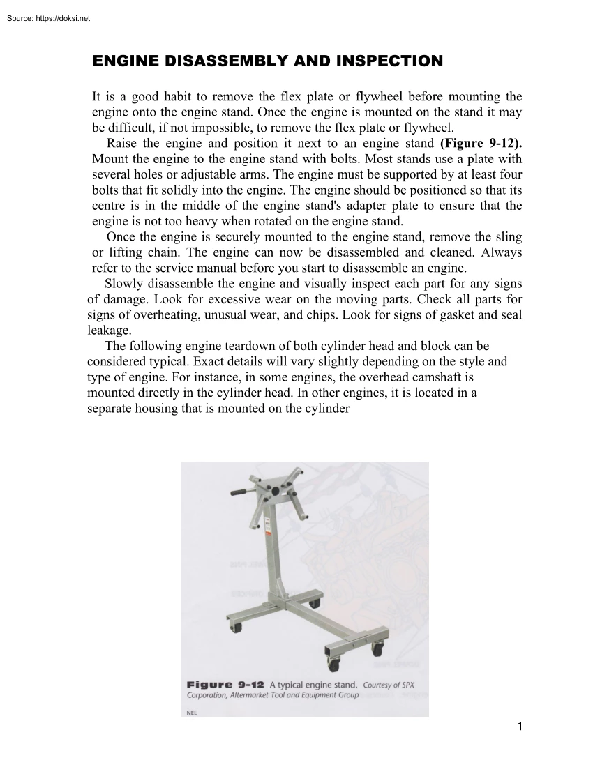
ENGINE DISASSEMBLY AND INSPECTION It is a good habit to remove the flex plate or flywheel before mounting the engine onto the engine stand. Once the engine is mounted on the stand it may be difficult, if not impossible, to remove the flex plate or flywheel. Raise the engine and position it next to an engine stand (Figure 9-12). Mount the engine to the engine stand with bolts. Most stands use a plate with several holes or adjustable arms. The engine must be supported by at least four bolts that fit solidly into the engine. The engine should be positioned so that its centre is in the middle of the engine stand's adapter plate to ensure that the engine is not too heavy when rotated on the engine stand. Once the engine is securely mounted to the engine stand, remove the sling or lifting chain. The engine can now be disassembled and cleaned Always refer to the service manual before you start to disassemble an engine. Slowly disassemble the engine and visually inspect each part for any
signs of damage. Look for excessive wear on the moving parts Check all parts for signs of overheating, unusual wear, and chips. Look for signs of gasket and seal leakage. The following engine teardown of both cylinder head and block can be considered typical. Exact details will vary slightly depending on the style and type of engine. For instance, in some engines, the overhead camshaft is mounted directly in the cylinder head. In other engines, it is located in a separate housing that is mounted on the cylinder 1 USING SERVICE MANUALS AND INFORMATION SYSTEMS Look up the specific model car and engine prior to disassembling the engine. ■ Cylinder Head Removal The first step in disassembly of an engine is usually the removal of the intake and exhaust manifolds. On some in-line engines, the intake and exhaust manifolds are often removed as an assembly. SHOP TALK It is important to let an aluminum cylinder head cool completely before removing it. ■ To start cylinder head
removal, remove the valve cover or covers and disassemble the rocker arm components. When removing the rocker assembly, check the manufacturer's manual or information system for specific instructions. After removing the rocker arm and pushrods, check the rocker area for sludge. Excessive buildup can indicate a poor oil change schedule and is a signal to look for similar wear patterns on other components. When removing the cylinder head, keep the pushrods and rocker arms or rocker arm assemblies in exact order. Use an organizing tray or label the parts with a felt-tipped marker to keep them together and labelled accurately. This type of organization aids greatly in diagnosing valve- related problems. Also, carefully check the lifters for dished bottoms or scratches, which indicate poor rotation (Figure 9-13). The cylinder head bolts are loosened one or two turns each, working from the outside of the cylinder head inward (Figure 9-14). This procedure prevents the distortion that can
occur if bolts are all loosened at once. The bolts are then removed, again following the outward to centre sequence. With the bolts removed, the cylinder head can be lifted off (Figure 9-15). The cylinder head gasket should be saved to compare with the new head gasket during reassembly. 2 3 On overhead valve engines, remove the timing cover. On some engines, this may require removing the oil pan. The harmonic balancer or vibration damper usually must also be removed. This normally requires a special puller The camshaft can now be carefully removed. Support the camshaft during removal to avoid dragging lobes over bearing surfaces, which would damage bearings and lobes. Do not bump cam lobe edges; this can cause chipping Some engines might require the removal of the thrust plate before taking out the camshaft. After the camshaft has been removed, visually examine it for any obvious defectsrounded lobes, edge wear, galling, and the like. If either the camshaft or lifters are
worn, both should be replaced. Do not install old valve lifters with a new camshaft. Do not install new valve lifters on a used camshaft Cylinder Block Disassembly After the cylinder head has been removed, the cylinder block can be torn down. First, remove the oil pan if it was not removed previously Then, remove the oil pump as directed in the service manual or information system. Continue the disassembly by removing the timing components. There are three different types of timing component assemblies: the chain and sprocket, the gear, and the timing belt and sprocket. Often the chain and sprocket assembly and the timing belt and sprocket assembly both have tensioners and guides. All three types of timing mechanisms should be replaced as complete assemblies during an engine overhaul. The tensioners and guides wear and should be replaced as well Some OHC engines have complicated drive systems; so if you are unsure of the removal process, consult the proper engine repair manual.
Inspect the sprockets for wear, cracks, and broken teeth. Inspect the timing gears for excessive backlash. Check the chain for slackness and wear Timing belts should always be replaced during an engine overhaul. 4 Carefully remove the cylinder ridge with a ridge reamer tool. Rotate the tool clockwise with a wrench to remove the ridge (Figure 9-20). Do not cut too deeply; an indentation may be left in the bore. Remove just enough metal to allow the piston assembly to slip out of the bore without causing damage to the bore. If the ridge is too large, the top rings will hit it and possibly break the ring lands. The ridge is formed at the top of the cylinder (Figure 9-21). Because the top ring stops traveling before it reaches the top of the cylinder, a ridge of unworn metal is left. Carbon also builds up above this ridge, adding to the problem If the ridge is not removed, the piston's ring lands may be damaged as the piston is driven out of its bore. After the ridge-removing
operation, wipe all the metal cuttings out of the cylinder. Use an oily rag to wipe the cylinder The cuttings will stick to it Prior to removal of the piston and rod assembly, check all connecting rods and main bearing caps for correct position and numbering. If the numbers are not visible, use a centre punch or number stamp to number them (Figure 9-22). Caps and rods should be stamped on the external flat surface. Remember, the caps and rods must remain as a set. 5 To remove the piston and rod assemblies, position the crankshaft throw at the bottom of its stroke. Remove the connecting rod nuts and cap Tap the cap lightly with a soft hammer or wood block to aid in cap removal. Cover the rod bolts with protectors to avoid damage to the crankshaft journals (Figure 9-23). Carefully push the piston and rod assembly out with the wooden hammer handle or wooden drift and support the piston by hand as it comes out of the 6 cylinder. Be sure the connecting rod does not damage the
cylinder during removal. With the bearing inserts in the rod and cap, replace the cap (numbers on same side) and install the nuts. Repeat the procedure for all other piston and rod assemblies. Remove the flywheel or flex plate. Mark the position of the flywheel on the crankshaft. This aids the reassembly of the engine In the specified order, loosen and remove the main bearing cap bolts and main bearing cap. Keeping the main bearing caps in order is very important. The location and position of each main bearing cap should be marked. After removing the main bearing caps, carefully take out the crankshaft by lifting both ends equally to avoid bending and damage. Store the crankshaft in a vertical position to avoid damage. Remove the main bearings and rear main oil seal from the block and the main bearing caps. Examine the bearing inserts for signs of abnormal engine conditions such as embedded metal particles, lack of lubrication, antifreeze contamination, oil dilution, uneven wear, and
wrong or undersized bearings. Inspect them for any unusual wear signs, and inspect the main bearing inserts for indications that they are oversized or undersized. Carefully inspect the main journals on the crankshaft for damage (Figure 9-24). The block cannot be thoroughly cleaned unless all core plugs (Figure 9-25) and oil gallery plugs are removed. It is imperative that all plugs be removed to allow for a thorough cleaning. To remove cup-type "frost” core plugs, drive them in and then use a pair of channel lock pliers to pull them out. Flat-type plugs can be removed by drilling a hole near the centre and then inserting a slide hammer to pull out the plug. In some engines, the cup-type plug can be removed easily by using a slide hammer or by driving the plug out from the backside with a long rod. 7 Sometimes removing threaded front and rear oil gallery plugs can be difficult. Using a drill and screw extractor can help. 8 After disassembly, the cylinder head and block
and their parts must be visually checked for cracks or other damage before they are cleaned as described in the next section. While inspecting the parts, check the bearings for undersizes and to see if the bearings are the original ones. If the engine has been previously torn down, use caution because a mistake could have been made during the last rebuild. Check for correct sizing before ordering any parts. 9
 Írásunkban a műelemzések készítésének módszertanát járjuk körül. Foglalkozunk az elemzés főbb fajtáival, szempontjaival és tanácsokat adunk az elemzés legfontosabb tartalmi elemeivel kapcsolatban is. Módszertani útmutatónk főként tanulók számára készült!