A doksi online olvasásához kérlek jelentkezz be!
A doksi online olvasásához kérlek jelentkezz be!
Nincs még értékelés. Legyél Te az első!
Legnépszerűbb doksik ebben a kategóriában


Tartalmi kivonat
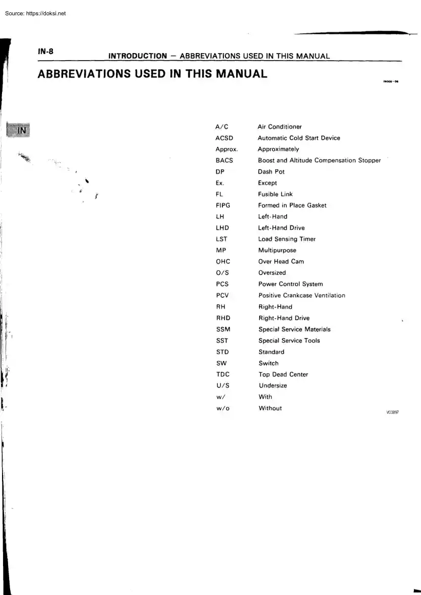
IN-8 INTRODUCTION - ABBREVIATIONS USED IN THIS MANUAL ABBREVIATIONS USED IN THIS MANUAL IM000-00 A/C Air Conditioner ACSD Automatic Cold Start Device Approx . Approximately BACS Boost and Altitude Compensation Stopper DP Dash Pot Ex . Except FL Fusible Link FIPG Formed in Place Gasket LH Left-Hand LHD Left-Hand Drive LST Load Sensing Timer MP Multipurpose OHC Over Head Cam O/S Oversized PCs Power Control System PCV Positive Crankcase Ventilation RH Right-Hand RHD Right-Hand Drive SSM Special Service Materials SST Special Service Tools STD Standard SW Switch TDC Top Dead Center U/S Undersize w/ With w/o Without 3697 IN-9 INTRODUCTION - STANDARD BOLT TORQUE SPECIFICATIONS STANDARD BOLT TORQUE SPECIFICATIONS INOOB-O1 HOW TO DETERMINE BOLT STRENGTH Mark Hexagon head bolt O Mark Class 4- 4T 5- 5T 6Bolt head No . 7- 6T 8- 8T 9- 9T 10- 10T 11- 11T Stud bolt 7T No mark 4T No mark 4T Class No mark u / 4T .i
Hexagon flange bolt w/ washer hexagon bolt '/ Grooved 0 6T Hexagon head bolt e Hexagon flange bolt w / washer hexagon bolt Hexagon head bolt p 0 o 2 protruding lines 5T 2 protruding lines 6T 3 protruding lines 7T u® ~ Welded bolt ~t 4T c Hexagon head bolt ~o \% 4 protruding lines 8T V013J78 IN-10 INTRODUCTION - STANDARD BOLT TORQUE SPECIFICATIONS SPECIFIED TORQUE FOR STANDARD BOLTS Specified torque Hexagon head bolt Hexagon flange bolt kgf •c m ft •Ibf N •m kgf •c m ft •I bf Diameter mm Pitch mm 4T 6 8 10 12 14 16 1 1 .25 1 .25 1 .25 1 .5 1 .5 5 12 .5 26 47 74 115 55 130 260 480 760 1,150 48 in . •1 bf, 9 19 35 55 83 6 14 29 53 84 - 60 145 290 540 850 - 52 in . •I bf 10 21 39 61 - 5T 6 8 10 12 14 16 1 1 .25 1 .25 1 .25 1 .5 1 .5 6.5 15.5 32 59 91 140 65 160 330 600 930 1,400 56 in . •I bf 12 24 43 67 101 7 .5 17 .5 36 65 100 - 75 175 360 670 1,050 - 65 in . •I bf 13 26 48 76 - 6T 6 8 10 12 14 16 1 1 .25 1 .25 1
.25 1 .5 1 .5 8 19 39 71 110 170 80 195 400 730 1,100 1,750 69 in . •I bf 14 29 53 80 127 9 21 44 80 125 - 90 210 440 810 1,250 - 78 in . •1 bf 15 32 59 90 - 7T 6 8 10 12 14 16 1 1 .25 1 .25 1 .25 1 .5 1 .5 10.5 25 52 95 145 230 110 260 530 970 1,500 2,300 8 19 38 70 108 166 12 28 58 105 165 - 120 290 590 1,050 1,700 - 9 21 43 76 123 - 8T 8 10 12 1 .25 1 .25 1 .25 29 61 110 300 620 1,100 22 45 80 33 68 120 330 690 1,250 24 50 90 9T 8 10 12 1 .25 1 .25 1 .25 34 70 125 340 710 1,300 25 51 94 37 78 140 380 790 1,450 27 57 105 10T 8 10 12 1 .25 1 .25 1 .25 38 78 140 390 800 1,450 28 58 105 42 88 1 55 430 890 1,600 31 64 116 11T 8 10 12 1 .25 1 .25 1 .25 42 87 155 430 890 1,600 31 64 116 47 97 175 480 990 1,800 35 72 130 Class N •m V00079 EG- 1 ENGINE ENGINE MECHANICAL EG- 2 OIL PRESSURE CHECK EG- 247 DESCRIPTION EG- 2 OIL AND FILTER REPLACEMENT EG- 248 OPERATION EG- 2 OIL PUMP EG - 250 PREPARATION EG- 4 OIL
COOLER TROUBLESHOOTING EG- 8 OIL NOZZLE EG-259 EG - 264 TUNE-UP EG- 14 SERVICE SPECIFICATIONS EG - 266 COMPRESSION CHECK EG- 29 TIMING BELT EG- 31 TIMING GEAR EG- 40 CYLINDER HEAD EG- 57 CYLINDER BLOCK EG- 87 SERVICE SPECIFICATIONS EG- 118 TURBOCHARGER SYSTEM DESCRIPTION EG-124 EG- 124 OPERATION EG-125 PREPARATION EG-126 PRECAUTION EG-127 TROUBLESHOOTING EG-128 TURBOCHARGER EG-130 TURBO PRESSURE SENSOR EG-140 SERVICE SPECIFICATIONS EG - 142 FUEL SYSTEM DESCRIPTION OPERATION EG-143 EG - 143 EG - 144 PREPARATION EG- 146 FUEL FILTER EG- 148 FUEL HEATER SYSTEM EG- 150 INJECTION NOZZLE EG- 152 INJECTION PUMP EG- 160 POWER CONTROL SYSTEM EG- 222 SERVICE SPECIFICATIONS EG- 224 COOLING SYSTEM EG-230 DESCRIPTION EG- 230 . EG- 230 PREPARATION EG- 232 OPERATION COOLANT CHECK AND REPLACEMENT . EG- 233 WATER PUMP EG- 234 THERMOSTAT EG- 239 RADIATOR EG- 241 SERVICE SPECIFICATIONS EG- 243
LUBRICATION SYSTEM DESCRIPTION EG- 244 EG- 244 . EG- 244 PREPARATION EG- 246 OPERATION ENGINE - ENGINE MECHANICAL ENGINE MECHANICAL DESCRIPTION The 1 KZ-T engine is a 3 .01- OHC turbo diesel engine OPERATION ENGINE - ENGINE MECHANICAL EG-3 Aluminum alloy is used for the cylinder head and resin for the cylinder head cover to reduce weight . The camshaft is belt driven and its serviceability has been increased by driving it with the injection pump gear . The belt tensioner is a hydraulic type to maintain appropriate tension The cylinder block has a balance shaft built into it to reduce engine vibration . For the idle gear between the crankshaft gear and injection pump gear a scissors type gear is used to reduce gear grinding noise . The crankshaft has a streamlined counterweight to reduce oil friction at high engine speeds . A cooling channel has been provided in the piston head to reduce heat transmission to the top ring groove .
To improve the durability of the top ring, FRM (Fiber Reinforced Metal) is embedded into it . Also, the groove has been positioned closer to the upper surface of the piston to reduce the volume of the piston chamber . The top of the piston is alumite-coated for greater heat resistance . EG-8 ENGINE - ENGINE MECHANICAL TROUBLESHOOTING Diesel Engine Daignosis EC31F-01 GENERAL Diesel engine problems are usually caused by the engine or fuel system . The injection pump is 1. 2. very rarely the cause of fuel system problems . Before beginning fues system tests, first check that the engine compression, valve timing and other major systems are within specifications . PRELIMINARY CHECKS 1 . Before performing fuel system checks, ensure that the engine is in good running condition . If necessary, first check the compression, timing and major components or systems . 2. 3. Check the air filter, and clean or replace it if necessary . Check that there is sufficient fuel in the tank . 4.
Check if the fuel is contaminated with gasoline or other foreign elements . Only good-quality diesel fuel should be used . Bleed air from the system by pumping the priming . 5. 6. 7. Check for water in the fuel filter and fuel tank, and drain as necessary . If the engine will not crank or if it cranks slowly, first troubleshoot the electrical system . EG-9 ENGINE - ENGINE MECHANICAL PRECAUTION : 1 . The basic troubleshooting procedures for the diesel engine (valve clearance compression, bearings, valves, pistons, etc ) are the same checks you would make for gasoline engine 2 . Repair of the injection pump requires considerable skill and use of a special test bench See page Lo z U Suspect area LO x 0 f"' o C N N o y Engine does not crank ` Engine cranks slowly 0 ° Engine cranks normally cc n ao F- H U) U) FU) F L, N 76 E Symptom L x 0 > Y S S y y m m LL in in 2 1 3 6 4 Vi (p tp N (n 0 M IU) E y V7 c Y G ~7 L y d U
'7 W w a N cs w c) w O~ d ; O c7 0 Z C O U N E c) .~ N u. >M 2 > 0 c J N LL L O I I U 4 0 U) 9 U7 .N C1 0. ui O C') N (D w U) c~ w O ~ U 4 -, 3 rn E A d d u J o z N ci r c U N I M w m r m U N tCp U 4 O N m U 4 E P (n O E O7 5 2 1 4 6 3 1 2 3 High engine idle speed `oo CL I C U 0 5 1 M w 2 Engine cranks normally 2 I Rough idle with warm engine 6 Lack of power 9 7 6 12 Engine suddenly stops 2 Engine does not shut off with key 1 Excessive exhaust smoke 4 Excessive fuel consumption 8 Engine overheat 4 2 5 5 8 1 1 2 3 2 3 10 5 2 1 7 1 7 Low oil pressure High oil pressure Engine noise when warm 2 1 HINT : When inspecting a wire harness or circuit the Electrical Wiring Diagram repair manual should be referred to and the circuits of related systems also should be checked . EG-10 ENGINE - ENGINE MECHANICAL See page (D N C7 w CD N C7 w 0) M 0) N w C7 w C7 0) M N C7 w cD C7 w (D
M N C7 w d M N at N w w C7 C7 N N C7 w 0 0 N W w M 0 N w O N c c c a CL A O E H m N d a N 0 E C) LL o Engine does not crank 8 p° y Engine cranks normally 3 c 0 C0 o ° m v o 0- N aD (7 w N CD C7 w N ID C7 w N aD C7 w t Suspect area Symptom ~ W if Y E ~ y ll ;, O O A M 3 cC a J C U N C E m 2 c0 a 0 m 0 y C N o e: 0 C O o cc C7 d CD y d C ~' p) ° c °~ -V Co y 4 U M U c) w SL d ) o m a`) d r c) FL 7 Engine cranks slowly 4 5 Engine cranks normally High engine idle speed Rough idle with warm engine 2 1 Lack of power 7 4 3 11 10 4 Engine suddenly stops Engine does not shut off with key N d 0 Excessive exhaust smoke Excessive fuel consumption Engine overheat Low oil pressure High oil pressure 4 6 9 2 5 2 3 6 4 3 1 8 3 2 1 4 9 5 1 Engine noise when warm VO39oo EG-1 1 ENGINE - ENGINE MECHANICAL Diesel Electrical System Diagnosis ENGINE DOES NOT START COLD HINT :
• Battery voltage at 12 V - Ignition switch OFF . • Engine cranks nomally . • Fusible link okay . • Check the voltage marked with an asterisk (*) just as the ignition switch is placed at ON because the voltage will change . Pre -Heating System Disconnect the water temperature sensor . Check if indicator light lights up with ignition switch ON . Light on : Approx . 6 seconds No Check fuse . (See page ST-28) Check for short circuit Fuse and repair if necessary . Blown Fuse OK Yes Check indicator light bulb . Bulb OK f Ignition switch OFF . Bulb No Good Replace bulb . Check for battery voltage to terminal S-IND of pre-heating timer connector (on wire harness side) . If okay, pre-heating timer is faulty and should be replaced . 1 'Check for battery voltage to terminal S-REL of pre-heating timer with ignition switch ON . No Voltage 'Check that there is 1 V or less to terminal CHG . If okay, timer is faulty and should be replaced . Voltage
'Check if voltage to terminal S-REL of pre-heating timer is terminated after engine is started . Yes Ignition switch OFF . CONTINUED ON PAGE EG-12 No Start engine and check if there is voltage at terminal CHG of pre-heating timer . If faulty, repair charging system as necessary . If okay, pre-heating timer is faulty and should be replaced . Pre-Heating Timer P08055 S-REL G-IND CHG V0W0 EG-12 ENGINE - ENGINE MECHANICAL 1 CONTINUED FROM PAGE EG-1 1 Place ignition switch at ON and check if current flow to terminal S-REL of timer is in accordance . Current flow : Approx . 120 seconds OK Pre-heating duration differs from the specified duration . No Voltage Timer is faulty and should be replaced . "After completion of pre-heating, check for voltage at terminal S-REL again when ignition switch is placed at START . No Voltage Voltage Ignition switch OFF . 'Place ignition switch at ON and check for voltage to glow plug a few seconds later . Thereafter, voltage
should drop about 1 /2 . No Voltage at All OK Voltage Remains at Battery Voltage or 1 /2 Battery Voltage 120 Seconds Check glow plug for resistance . Approx . 0 c2 Glow plug okay. Connect water temperature sensor . Infinity Replace glow plug relays . Glow plug relay is faulty and should be replaced . Glow plug is faulty and should be replaced . ENGINE - ENGINE MECHANICAL EG-13 Fuel Cut Solenoid Valve With ignition switch turned ON, check for fuel cut solenoid valve operation noise (clicking sound) while repeatedly Noise Fuel cut solenoid valve okay. connecting and disconnecting fuel cut solenoid valve . No Noise Check fuse . Fuse OK Apply battery voltage directly to solenoid, and check for noise . Fuse Blown Noise Check for short circuit, and repair as necessary . Check wire harness from fuse to fuel cut solenoid . No Noise Replace fuel cut solenoid valve. n EG-14 ENGINE - ENGINE MECHANICAL TUNE-UP ENGINE COOLANT INSPECTION 1. CHECK ENGINE COOLANT LEVEL
AT RESERVOIR TANK The engine coolant level should be between the "LOW" and "FULL" lines . If low, check for leaks and add engine coolant up to the "FULL" line . 2. (a) CHECK ENGINE COOLANT QUALITY Remove the radiator cap . CAUTION : To avoid the danger of being burned, do not remove the radiator cap while the engine and radiator are still hot, as fluid and steam can be blown out under pressure . There should not be any excessive deposits of rust or scale around the radiator cap or radiator filler hole, and the coolant should be free from oil . If excessively dirty, replace the coolant . Reinstall the radiator cap . (b) (c) ENGINE OIL INSPECTION Recommended Viscosity (SAE) : I I I 15W-40 I 20W-40 I I 1 OW-40 I I I I I 20W-50 1OW-50 1 I CHECK OIL QUALITY Check the oil for deterioration, entry of water, discoloring or thinning . If oil quality is visibly poor, replace it . Oil grade : API grade CD or better Recommended viscosity : Refer
to illustration 2. CHECK ENGINE OIL LEVEL The oil level should be between the "L" and "F" marks on the dipstick . If low, check for leakage and add oil up to the "F" mark . NOTICE : Do not fill with engine oil above the "F" mark . IOW-30 "C-29 °F--20 - 18 0 -7 20 I 30 1 1 4 40 I 16 60 27 80 EGOM-0D 1 . 5W 30 20 EGUG-01 38 100 TFMvFRATURE RANCE ANTICIPATED BEFORE NFXT OIL CHANGE P13174 ENGINE - ENGINE MECHANICAL EG-15 BATTERY INSPECTION Upper Level Lower Level 1. CHECK BATTERY SPECIFIC GRAVITY AND (a) ELECTROLYTE LEVEL Check the electrolyte quantity of each cell . E017T-03 If insufficient, refill with distilled (or purified) water . (b) Check the specific gravity of each cell . Standard specific gravity at 20°C (68°F) : 1 .27 - 1 29 P12879 If not within specifications, charge the battery . 2 . CHECK BATTERY TERMINALS, FUSIBLE LINK AND FUSES (a) Check that the battery terminals are not loose or corroded .
(b) Check the fusible links and fuses for continuity . E034H AIR FILTER INSPECTION AND CLEANING 01 Paper Filter Type : 1. INSPECT AIR FILTER Visually check that the filter element is not excessively dirty, damaged or oily . 2. CLEAN AIR FILTER Clean the filter element with compressed air . First blow from the inside thoroughly . Then blow off the outside of the filter element . Washable Type: 1. INSPECT AIR FILTER 2. Visually check that the filter element is not excessively dirty, damaged or oily . CLEAN AIR FILTER (a) Blow dirt off in the filter element with compressed air . (b) Submerge the filter element in the water and agitate it up and down more than 10 times . (c) Repeat rinsing in clean water until rinsing water is clear . EG-16 ENGINE - ENGINE MECHANICAL (d) (e) Remove excess water by shaking the filter element or blowing with compressed air. NOTICE : Do not beat or drop filter element . Wipe off dust on the air cleaner case interior . ALTERNATOR DRIVE BELT
INSPECTION INSPECT DRIVE BELT (a) Visually check the belt for cracks, oiliness or wear . Check that the belt does not touch the bottom of the pulley groove. If one belt has any of the above defects, replace both belts. (b) Check the drive belt deflection by pressing on the belt at the points indicated in the illustration with 98 N (10 kgf, 22 lbf) of pressure . Deflection : New belt 6 - 8 mm (0 .24 - 031 in ) Used belt 8 - 12 mm (0 .31 - 0 47 in ) If the deflection is not as specified, adjust it . Reference Using SST, check the drive belt tension . SST A 09216-00020 SST B 09216-00030 Drive belt tension : New belt 38 - 62 kgf Used belt 20 - 40 kgf ENGINE - ENGINE MECHANICAL EG-17 HINT: • "New belt" refers to a belt which has been used less than 5 minutes on a running engine . • "Used belt" refers to a belt which has been used on a running engine for 5 minutes or more . • After installing a new belt, run the engine for about 5 minutes and recheck the
belt deflection or belt tension . GLOW PLUGS INSPECTION E0340-01 NOTICE : When checking the resistance of the glow plugs, do it with the engine installed . Keep removal and installation of the glow plugs to a minimum . INSPECT GLOW PLUGS (See page ST-33) Using an ohmmeter, that there is continuity between the glow plug terminal and ground . Resistance (Cold) : Approx . 065 Q If the resistance exceeds 1 .0 0, replace the glow plug VALVE CLEARANCE INSPECTION AND ADJUSTMENT E034L-01 HINT : Inspect and adjust the valve clearance when the engine is cold . 1. (a) (b) (c) REMOVE INTAKE PIPE Disconnect the VSV connector and 2 vacuum hoses . Disconnect the 2 wire harness clamps . Remove the 4 nuts and seal washers . Ct7' 1 8 ENGINE - ENGINE MECHANICAL (d) Disconnect the 2 PCV hoses . (e) Use pliers to . pinch the ends of the clamp togetho until the lock plate engages the catch . Make sure the lock plate and catch are engaged si curely . (f) Remove the intake pipe and gasket
. 2. REMOVE CYLINDER HEAD COVER Remove the 10 bolts, 2 nuts, cylinder head cover an gasket . 3. SET NO .4 CYLINDER TO TDC/COMPRESSION (a) Turn the crankshaft pulley clockwise, and align i1 groove with the timing pointer . (b) Check that the valve lifters on the No .4 cylinder ar loose and valve lifters on the No .1 cylinder are tight If not, turn the crankshaft one revolution (360 0 ) an align the mark as above . 4. (a) ADJUST VALVE CLEARANCE Check only the valves indicated in the illustration . • • Using a thickness gauge, measure the clearanc between the valve lifter and camshaft . Record the out - of - specification valve cleat ance measurements . They will be used later t determine the required replacement adjustirr shim . Valve clearance (Cold) : Intake 0 .20 - 0 30 mm (0 008 - 0 012 in ) Exhaust 0 .25 - 0 35 mm (0 010 - 0 014 in ) (b) Turn the crankshaft pulley one revolution (360°) an align the mark as above (See procedure step 4) . ENGINE - ENGINE MECHANICAL
EG-19 (c) Check only the valves indicated as shown . Measure the valve clearance . (See procedure in step (a)) (d) Remove the adjusting shim . • Turn the crankshaft to position the cam lob of the camshaft on the adjusting valve upward . • Using SST, press down the valve lifter. SST 09 248 - 64010 HINT : Before pressing down the valve lifter, position the notch on the exhaust manifold side . • (e) Remove the adjusting shim with small screwdriver and magnetic finger . Determine the replacement adjusting shim size by using following the formula or charts : Using a micrometer, measure the thickness of • • T A the shim which was removed . Calculate the thickness of the new shim so the valve clearance comes within specified value . Thickness of removed shim Measured valve clearance N Intake : Thickness of new shim • = T + (A - 0 .25 mm (0 010 in )) Exhaust :-- • • =T+(A-0 .30 mm (0 012 in )) Select a new shim with a thickness as close as possible to the
calculated values . HINT : Shims are available in 17 sized in increments of 0 .050 mm (0 0020 in ), from 2 500 mm (0 0984 in ) to 3 .300 mm (0 1299 in ) , EG-20 ENGINE - ENGINE MECHANICAL Adjusting Shim Selection Using Chart INTAKE Installed shim thickness Measured clearance mm (in .) 0.000-0 020 0 0000 - 0 0008 0021-0040 00008 0 .0016 0 .041 - 0060 0 0016 - 00024 0.061 0 080 0 0024 - 00031 0061-0 .100 00032-00039 0 .101 0 120 00040-0 0047 0.121 0140 00048-0-0055 0141 - 0160 0 0056 - 0.0063 0161-0180 00063-0.0071 0.181-0 199 00071 00078 0.200 - 0300 (0 0079 - 00118) 0 .301 - 0 320 00119 - 0 0126 0.321 - 0340 00126 - 0 0134 0.341 - 0 360 00134 - 0 0142 0.361 - 0380 00142 - 0 0150 0.381 - 0400 00150 - 0 0157 0 .401 - 0420 00158 - 0 0165 0.421 - 0440 00166 - 0 0173 0.441 - 0460 00174 - 0 0181 0.461 - 0480 0 0181 - 0 0189 0 .481 - 0500 0 0189 - 0 0197 0 .501 - 0520 00197 - 0 0205 0 .521 - 0540 00205 - 0 0213 0 .541 - 0 560 00213 - 0 0220 0 .561 - 0 580 00221 - 0 0228 0 .581 - 0
600 0 0229 - 0 0236 0 .601 - 0 620 0 0237 - 0 0244 0 .621 - 0640 0 0244 - 0 0252 0 .641 - 0 660 0 0252 - 0 0260 0 .661 - 0 680 0 0260 - 0 0268 0 681 - 0 .700 0,0268 - 0 0276 0 .701 - 0 720 0,0276 - 0 0283 0 .721 - 0 740 0 0284 - 0 0291 0 .741 - 0 760 0 0292 - 0 0299 0.761 - 0780 00300 - 0 0307 0.781 - 0800 00307 - 0 0315 0.801 - 0820 00315 - 0 0323 0.821 -0840 00323 - 0 0331 0.841 - 0860 00331 - 0 0339 0.861-0880 00339 - 0 0346 0.881 - 0 900 00347 - 0 0354 0901 -0.920 00355 - 0 0362 0 .921 - 0940 0 0363 - 00370 0 .941 - 0960 0 0370 - 00378 0 .961- 0 980 0 0378 - 0 0386 0 .981 1 000 (0 0386 00394) 1 .001 - 1 020 (0 0394 - 0 0402) 1 .021 - 1 040 (0 0402 - 0 0409) 1 .041 - 1 060 (0 0410 - 0 0417) 1 061 - 1 .080 (0 0418 - 00425) 1 .081 - 1 100 (0 0426 - 0 0433) mm (in ) ., .- .- m ro O QI n Y7 th O m rp N m .- m 1n t0 r0 ^ .0 m ao A O O .- N N N N N N N N N N N N N N N N N N O r O c o 0 0 0 0 0 0 0 0 0 0 0' o ' o 0 0 0 0 0 0 0 0 0 0 0 0 0 0 0 0 0 0 0 0 o 0 0 0 0 0 0 0 0 0 0 0
O 00 O O N O N VN ON. N10 O N N o N d N NW M N. ONr d N N n N N. N yO) N W N .- r N N N N b N N N N N N lV CI N fV N N N tV N N N N rV tV fV fV N rV tV N fh th C7 t7 f•! Pf f+l Pl (.j (M C'7 th C7 {+j {+j rj r+j rj rj p N M fh V O rn tp r- r m OD O O O O O O O 0 O O O 0 O O 0 - . .- N ' Of 1 01 1 1 1 ' mmm31:mmamm:43 :-M13 :M :EmmmmMM1131> MMMMm3131®MMMMmMMM ∎m9mmmmm :f1-mm :!<P.!<FkJmmmma!mmmmmmmmmmmmmommmmmm mmmmmmmmmmmmmmmmmmmmmmm Lmmm 'mmmmmmmom37m'i1mm CM' tM' MMMMMMMMMM . MMMGM . MMMM ME 01 m',1i1mmmmm .m :M . 'MmmmmmmM 0101 9MMMMM-MMm-lmmmmmmMi>oln~M R~:~MMMMM .,~a ,`TtM3M3~E~~~7~r7amam 01 01 01 Mr71s3i'8MMMM. MMMmmmiM'm1>3MMIaJ :~:M~31MM i1iZ'JiM' MOMOMMMM MM 0101 0101 :8m :l:1mm:onm :!<lmmmmmmmmmmmmmmmmmmmmmmmmmmlmlmlmM :° 1010101 42M , MMMMmmmmmmMmm113MIDMMM31mmMMMM3MMM57~r79i131mMMMmE; 1 0 1 0142 4 2MsMM;(c]~c]mmmMhS'IMMMmMIMMIMMM IMMIM'rM .GM .313131MMcMM;McM'cM
.M4,t131424206 MI MIMMMmmmmMMMMMMMM4M'rMMMMMMSM.CM .MMMMM4MMMM mmcM.RMlZ• 2' r6 I . 6 t 31111 1 1 , 4-4 61616165 52121 1 1 , 6-6 6e6e6 6- 31 e1 e1 1 , 8 8e636c c6 9mmm;MmM ~~~ :!<Ts:]~lmmmme,0g0' mmm :!•3 ~~~31®®'51~~~~~~7~7~7mDm~~~., ~~~e,0 ~l~mmmmm ~~m~lmmmmmmmmmmmmmm~l~lmmm~~~mmmm~lammm~~~mmmmmam~l mmmmmmmmmmmmmmmmmmmmmmmmmmmmmmmmmmmmmmmmmmmm mmmmmmmmmmmmmmmmmmmmmmmmmmmmmmmmmmmmmmmmmmm mmmmmmmmmmmmmmmmmmmmmmmmmmmmmmm mmmmmmmmmm mmmMmmmmmMmmmmmmmmMMMMMMMMMMMmMMMmmmmmmmM mmmmmmmmmmmmmmmmmmmmmmmmmmmmmmmmmmmmmmmm mmmmmmmmmmmmmmmmmmmmmmmmmmmmmmmmmmmmmm mmmmmmmmmmmmmmmmmmmmmmmmmmmmmmmmmmmmm m16M16MMMMM,31'e2,M'eM. MM'eM MM-31M'MMMMeM'M'eM MMMMMMMM mmmmmmmmmmmmmmmmmmmmmmmmMMMmmmmmmaM mmmmmm®mmmmIm0,BmmmmmammmMIm-MMmmmmmmm mmmmmmMmmmMMOmmmmmammmmmmmmmmmmm mmmmm MMEMIMMmmmMmmMmmmmmmmmmmmm m~lm~lmm~m~~~lmm~lam~m~~~~mmmmmmT mmmmmmMMmmMM-31MM MOM MmmMmmmmM mmmmmIMMMMM MMMMmmIMM mmmmmmMM 01 MM1MMC'11' MMMMMMMMMMMMMM
731mmmm mMMMImmmmamMUMmIMMmmmmmm31 MI: M mmmmia-1laMMMCOME! mmmmmmm E MMMmmmamMMMIMMMImmmm3lmm51 MmmmmaamM-MQMMMMMmmmM mmmID®mMMIM-M-0 mmmmmm3 mm3lmmMMOM mmmmm3l51 mmilmmm001MmmmammmM mmMMMIMMIMmMmmmmmM m11MM0,30mmmm3131M ~~~~~~mmmmmmT ~inin~~~mmm~hi M11Mmmm31mmm31 :00mmmm3T 9 .9 1 1 9111 11111 1111 New shim thickness Shim Thickness . 01 2 .50 (0 0984) 42 2 .55 (0 1004) 2 .60 (0 1024) 06 43 2 .65 (0 1043) 11 2 .70 (0 1063) 44 2 .75 (0 1083) 16 2 .80 (0 1102) 2 .85 (0 1122) 45 21 2 .90 (0 1142) Shim No . 46 26 47 31 48 36 49 41 mm (in .) Thickness 2 .95 (0 1 161) 3 .00 (0 1 181) 3 .05 (0 1201) 3 .10 (0 1220) 3 .15 (0 1240) 3 .20 (0 1260) 3 .25 (0 1280) 3 .30 (0 1299) Intake valve clearance (Cold) : 0 .20 - 0 30 mm (0 008 - 0 012 in ) EXAMPLE : The 2 .800 mm (0 1102 in ) shim is installed and the measured clearance is 0 .350 mm (0 0138 in ) Replace the 2 .800 mm (0 1102 in ) shim with a No 21 shim . V03782 EG-21 ENGINE - ENGINE MECHANICAL Adjusting Shim Selection Using
Chart EXHAUST ~ Measured clearance mm (in 0000 - 0020 0 .0000 0 0008) 0.021 - 0040 0 0008 0 0016 0 .041 0060 0 0016 - 0 0024 0 .061 0080 0 0024 - 0 0031 0081 0.100 0 0032 0 0039 0101 - 0.120 (0 0040 0 0047 0 .121 0.140 0 0048 0 0055 0 .141 0160 00056 0 0063 0161 - 0.180 (00063 0 0071 0 .181 0.200 (00071 - 00079 0201 - 0 .220 00079 00087 0 .221 -0 240 00087 0 0094 0 .241 - 0 249 (00095 - 00098 0 .250 - 0 350 00098 00138 0.351- 0 360 00138 - 00142) 0 .361 - 0 380 (00142 - 00150 0 .381 - 0400 00150 - 00157 0.401- 0 420 (00158 - 00165 0.421 - 0 440 00166 - 00173 0.4 1 - 0 460 00174 - 00181 0.461 0480 00181 -00189 0.481 - 0 500 (00189 - 00197 0501 -0 520 0.0197 - 00205 0521 0 540 0.0205 - 00213 0 541 0 560 0.0213 - 00220 0561 0 580 0.0221 - 00228 0.581 0 600 00229 - 00236 0.601 0 620 00237 - 0 0244 0.621 - 0640 0,0244 - 00252 0.641 -- 0 660 00252 - 00260 0.661 - 0 680 00260 00268 0.681 0 700 0 0268 0 0276 0.701 0720 0 0276 0 0283 0.721 0 740 (0 0284 00291 0741 -0760 0 .0292 00299 0761
0.780 0 0300 - 0 0307 0781 0.800 (0 0307 - 0 0315 0801 0 .820 0 0315 - 0 0323 0 821 0.840 (0 0323 - 0 0331 0841 0 860 00331 - 0 .0339 0861 0.880 00339 - 0 0346 0881 - 0.900 00347 - 00354 0901 0.920 (00355 - 00362 0 921 0 .940 00363 - 00370 0.941 0960 00370 - 00378 0961 0 .980 00378 - 00386 0.981 1 .000 00386 - 00394 1 .001 .020 00394 - 00402 1021 -1040 0.0402 - 00409 1041 -1 .060 (00410 - 00417) 1 .061 - 1 080 (00418 - 00425) 1 .081 - 1 100 (00426 - 00433) 1 .101 - 1 120 (00433 - 00441) 1 121 -1 140 (0.0441 - 00449) 1141,-1 .150 (0 0449 - 0 0453) N a c~ r Ln ~ - - OO8-d-8 .-~ p~ f•7 r Installed shim thickness O W N N n l. mm n 17 W jp '~ N N N N N N N N N N N N n O O ^ -----^ N- - ° ~ 0 0 0 0 0 0 0 0 0 0 0 0 0 0 0 0 0 0 O O O O O O OO O O O O O O O O O O O O O O O O O O O O O O O N N N N N M M M M M M M M M PI (•j kM M M M M M M M N N N N N N N N N N N N N N N N kV N N N N N ∎mmmmmmmmmmmmmmmmmma mEMEEmMMMMMmmmmmmmmmmmmmmmmam
∎mmmmmmmmmmmmmmmmmmMMmmmmmmmmmommmmmmmmmmmmmmaams ∎mmmmmmmmmmmmmmmmmmmmmmmmmmmmmmmmmmmmmmmmmmmmmm5mz mommoo •mommmmmmmmmmmmmmmmmmmmmmmmmmmmmmmmmmmmmmmm mommommommmmmmmmmmmmmmmmmmmmmmmmmmmmmmmmmmmmmmmmm ∎mmmmmmmmmmmmmmunmmmmiDininmmmmmmmmmmmmmmL'. mom :F mmmmmm ∎mmmmmmmmmmmmmmmmmmmmmmmmmmmmmmmmmmmmmmmmSmmlmmmmm ∎∎mmmmmmmm5mmommmm :k157mmmmmmmminmmmmmmmmmEmmm5mm mmm= mmmmmmmm5mmmmmmmmmmmmmmmmmmmmmmmmmmmmmm5m5m757m mmmmo ~/mmmmm5757mmmm~lm~lmmmm~~~mmm~~~i~m :f~m~'::33~3j37a1m :Fl~mal'~~a3mE:I•'. mmmmmmmmsmmmmmmmmmmmmmmmmmmmmmmmmmmmmmmmmmmmmoomm mmmmmmmmmm~*~mmmmmmmmmmmmmmmmmmmmmmmmmmmmmmmmmmmm∎ Samm ME mmmmmm : 7mmmmmmmmmmmMMMMOMmmmmmmM0mmmmmmmammm mmm~mmmmm®m~mQmmmmmmmmmmmmaa5757~73Immmmmaaa~l~lmmm~mm mmmmmmmmmmmmmmmmmmmmmmmmmmmmmmmmmmmmmimmmmmmmmm mm 7 7mmlnmmmmmlnmmmmmmmmmmaa57~I57573t®mmmmao =M3131mm mmmmmmmmmmmmmmmmmmmmmmmmmmmmmammmommEmmmmmmm mmmmmmmmmmmmmmmmmmmmmmmmmmaaammmomom173lmmam mmmmmmmmmmmmmmmmmmmmmmmmmmaammmomommmmmmmm
mmmmmmMMMMMmmmmmmmmm5757MMMMMMMMMMMM7M!EMMMMM mmmmmmmmmmmmmmmmmmm5mmmmmmmmmmoo mmmmmmm mmmmmmmmmmmmmmmmmmmmmmmmmmmmommmmmmmmm mmmmmmmmmmmmmM , : MMM 7MMMMMMMMMMMM 75lmamm mmmmmommmmmommmmmmmmmmmmommmmmmmmm m~:Fi :~Sj;~~mma~~' E~E~ :F1 :F157~r7 1®X515]' 07 !!] :~7 :~] :!]:0 :11a51 :II mS~m~Immmmmmmmm575757573im~m~~ao >,~1m5]~1mam mmmmmmmmmmmm5mmmmmmmmmomommmmmmmm mmmmmm5 MOMM57MMMMMMMmmmommmmmmmm mmRIMMMMoam575757m3131mM-MOM MM2131mam MM MM ,~MMM5757575 MMM- M'M :I3Moa::la :!`7575IMMMM mmmmmoa57575757m31m515)mao~lm~l~lammm m':~~mm~575757~~~mOS3ooo :Fltl7:Fl5I~a51' mmomm5757mammmmmmmommma3lmam mmom5757573131m' 57 57am5lMm mm5757MmmmMmmmamM . Mmmmmmmm 575757931x51MMOO0 :0MM 131a!1m S757mmiammmooammmmmmmm 5~-757:JI51MMM mM MM MM amammm omamm m!H mm m U1II 1 1 41 1 1 41 1 New shim thickness mm in . Thickness Shim 01 2 .50 (0 0984) 42 2 .55 (0,1004) 46 2 .95 (0 1161) 26 3 .00 (01181) 47 3 .05 (0 1201) 31 3 .10 (0 1220) 48 3 .15 (0 1240)
36 3 .20 (0 1260) Nam Thickness 06 2 .60 (0 1024) 43 2 .65 (0 1043) 11 2 .70 (0,1063) 44 2 .75 (01083) 16 2 .80 (0 1102) 45 49 3 .25 (0 1280) 2 .85 (0 1122) 41 21 2 .90 (0 1142) 3 .30 (0 1299) Exhaust valve clearance : 0 .25 - 0 35 mm (0 010 - 0 014) EXAMPLE : The 2 .800 mm (0 1102 in ) shim is installed and the measured clearance is 0 .390 mm (0 0154 in ) Replace the 2 .900 mm (0 1142 in ) shim with a No 11 shim V03783 EGN- ENGINE MECHANICAL (f) (g) Install a new adjusting shim . Place a new adjusting shim on the valve lifter . • Remove the SST . • SST 09248-64010 Recheck the valve clearance . 5. (a) (b) INSTALL CYLINDER HEAD COVER Remove any old packing (FIPG) material . Apply seal packing to the cylinder head as shown in the illustration . Seal packing : Part No . 08826-00080 or equivalent (c) (d) Install the gasket to the cylinder head cover . Install the cylinder head cover with the 10 bolts and 2 nuts . Torque : 9 N •m (90 kgf •c m,
78 in . •I bf) 6. (a) (b) (c) INSTALL INTAKE PIPE Place a new gasket on the intake manifold . Connect the air hose and install the intake pipe . Press the clamp lock together with pliers and press down the tip of the lock plate . Carefully let the lock spread apart . Take care not to let the pliers slip . Connect the 2 PCV hoses . (d) (e) (f) (g) Install the 4 seal washers and nuts . 12 N •m (120 kgf •c m, 9 ft •I bf) Connect the 2 wire harness clamps . Connect the VSV connector and 2 vacuum hoses . ENGINE - ENGINE MECHANICAL INJECTION TIMING INSPECTION AND ADJUSTMENT 1. (a) EG-23 EG34M-01 INSTALL SST AND DIAL INDICATOR Remove the plug bolt and gasket from the distributive head plug of the injection pump . (b) Install SST (plunger stroke measuring tool) and a dial indicator to the plug bolt hole of distributive head plug . SST 09275-54011 2. SET NO .1 OR NO 4 CYLINDER TO 25 ° OR MORE BTDC/COMPRESSION Turn the crankshaft pulley counterclockwise, so the pulley
groove is 25 ° or more from the timing pointer . 3. (a) w/ ACSD : RELEASE ACSD ADVANCE Using a screwdriver, turn the cold starting lever counterclockwise approx . 20° (b) Put a metal plate (thickness of 8 .5 - 10 mm (0 335 0 394 in )) between the cold starting lever and thermo wax plunger . 4. (a) ADJUST INJECTION TIMING Set the dial indicator at 0 mm (0 in .) (b) Recheck to see that the dial indicator remains at 0 mm (0 in .) while slightly rotating the crankshaft pulley clockwise or counterclockwise . (c) Slowly rotate the crankshaft pulley clockwise until pulley groove is aligned with the timing pointer. (d) Measure the plunger stroke . Plunger stroke : Europe 0 .39 - 0 43 mm (0 0154 - 0 0169 in ) Others 0 .58 - 0 62 mm (0 0228 - 0 0244 in ) EG-24 ENGINE - ENGINE MECHANICAL (e) Loosen the following nuts and bolt : (1) 4 union nuts of injection pipes at injection pump side (2) Bolt holding injection pump to injection pump stay (3) 2 nuts holding injection pump to
timing gear case (f) Adjust plunger stroke by slightly tilting the injection pump body . If the stroke is less than specification, tilt the pump toward the engine . If the stroke is greater than specification, tilt the pump away from the engine . (g) Tighten the following nuts and bolt : (1) 2 nuts holding injection pump to timing gear case Torque : 21 N .m (210 kgf cm, 15 ft Ibf) ENGINE - ENGINE MECHANICAL EG-25 (2) Bolt holding injection pump to injection pump stay Torque: 32 N .m (330 kgfcm, 24 ft •I bf) • Recheck the plunger stroke . 12439 5. (3) 4 union nuts of injection pipes Torque : 15 N .m (150 kgfcm, 11 ft Ibf) w/ ACSD: REMOVE METAL PLATE 6. (a) REMOVE SST AND DIAL INDICATOR Remove the SST and dial indicator . SST 09275-54011 (b) Install a new gasket and the plug bolt of the distributive head plug . Torque : 25.5 N m (260 kgf cm, 19 ft Ibf) 7. START ENGINE AND CHECK FOR LEAKAGE EG-26 ENGINE - ENGINE MECHANICAL IDLE SPEED AND MAXIMUM SPEED INSPECTION
AND ADJUSTMENT E634N-m 1. INITIAL CONDITIONS (a) Engine at normal operating temperature (b) Air cleaner installed (c) All accessories switched OFF (d) All vacuum lines properly connected (e) Valve clearance set correctly (f) Injection timing set correctly 2. CONNECT TACHOMETER 3. ADJUST IDLE SPEED (a) Check that the adjusting lever touches the idle speed adjusting screw when the accelerator pedal is released . If not, adjust the accelerator linkage . (b) Start the engine . (c) Check the idle speed . Idle speed : 700±50 rpm (d) Adjust the idle speed . • • Disconnect the accelerator likage . Loosen the lock nut of the idle speed adjusting screw . • Adjust the idle speed by turning the IDLE SPEED ADJUSTING SCREW . Idle speed : 700 rpm • • • Securely tighten the lock nut, and recheck the idle speed . Reconnect the accelerator linkage . After adjustment, adjust the accelerator linkage . ENGINE - ENGINE MECHANICAL 4. (a) (b) (c) (d) EG-27 ADJUST MAXIMUM SPEED
Check that the adjusting lever touches the maximum speed adjusting screw when the accelerator pedal is depressed all the way . If not, adjust the accelerator linkage . Start the engine . Depress the accelerator pedal all the way . Check the maximum speed . Maximum speed : 4600±130 rpm If the maximum speed is not as specified, refer to INJECTION PUMP ADJUSTMENT (See page EG197). EG-28 ENGINE - ENGINE MECHANICAL EGLP-01 AIR CONDITIONER IDLE-UP SETTING SPEED INSPECTION AND ADJUSTMENT 1 . INITIAL CONDITIONS (a) Engine at normal operating temperature (b) Air cleaner installed (c) All vacuum lines properly connected (d) Valve clearance set correctly (e) Injection timing set correctly (f) Idle speed set correctly 2 . CONNECT TACHOMETER 3. ADJUST AIR CONDITIONER IDLE - UP SETTING SPEED (a) Start the engine . (b) A/C switches ON . (c) Disconnect the vacuum hose from the idle-up actuator . (d) Apply vacuum to the idle-up actuator . (e) Race the engine to 2,500 rpm for a few seconds,
release the throttle and check the idle-up setting speed . A/C idle-up setting speed : 950 rpm (f) Adjust the idle-upsetting speed by turning the IDLE -UP SETTING SPEED ADJUSTING SCREW . (g) Race the engine to 2,500 rpm for a few seconds, release the throttle and recheck the A/C idle-up setting speed . (h) Reconnect the vacuum hose to the idle-up actuator . ENGINE - ENGINE MECHANICAL EG-29 COMPRESSION CHECK 'G340-01 HINT : If there is lack of power, excessive oil consump- tion or poor fuel economy, measure the compression pressure . 1. WARM UP AND STOP ENGINE Allow the engine to warm up to normal operating temperature . 2. DISCONNECT INJECTION PUMP (FUEL CUT 3. SOLENOID) CONNECTOR REMOVE INJECTION NOZZLES (See page EG-152) 4. (a) CHECK CYLINDER COMPRESSION PRESSURE Install an attachment to the injection nozzle hole . BANZAI TDG-1 F (TDG-12) IYASAKA DCG-UTTN-2 (No .34) (b) Connect a compression gauge to the attachment . BANZAI TDG-1 F IYASAKA DCG-UTTN-2 (c)
While cranking the engine, measure the compression pressure . HINT : Always use a fully charged battery to obtain engine revolution of 250 rpm or more . (d) Repeat steps (a) through (c) for each cylinder . NOTICE : This measurement must be done in as short a time as possible . EG-30 ENGINE - ENGINE MECHANICAL (e) 5. Compression pressure : 3,040 kPa (31 .0 kgf/cm', 441 psi) or more Minimum pressure : 1,961 kPa (20 .0 kgf/cm', 284 psi) Difference between each cylinder : 490 kPa (5 .0 kgf/cm', 71 psi) or less If the cylinder compression in one or more cylinders is low, pour a small amount of engine oil into the cylinder through the injection nozzle hole and repeat steps (a) through (c) for the cylinder with low compression . • If adding oil helps the compression, chances are that the piston rings and/or cylinder bore are worn or damaged . • If pressure stays low, a valve may be sticking or seating improperly, or there may be leakage past the gasket . REINSTALL
INJECTION NOZZLES (See page EG -158) 6. RECONNECT INJECTION PUMP (FUEL CUT SOLENOID) CONNECTOR 7. START ENGINE AND CHECK FUEL LEAKAGE EG-31 ENGINE - ENGINE MECHANICAL TIMING BELT EG 17P-03 HINT : If replacing the timing belt before the timing belt warning light comes on, (light comes on after 100,000 km of driving), be sure to reset the timing belt counter of the speedometer to zero . COMPONENTS FOR REMOVAL AND INSTALLATION 9 (90, 78 in . - lbf) i 12(120, 9) Intake Pipe No .2 Air Hose • Gasket 98 (1,000 . 72) 13 (130,9) N •m (kgf •c m, ft-lbf) • Non-reusable part F I 1'e, EG-32 ENGINE - ENGINE MECHANICAL TIMING BELT REMOVAL EG13N-01 (See Components for Removal and Installation) 1. REMOVE TIMING BELT COVER Remove the 4 bolts, seal washers, 2 clips, timing belt cover and gasket . 2. SET NO .4 CYLINDER TO TDC/COMPRESSION Turn the crankshaft pulley clockwise, set both No .1 and No .2 camshaft pulley grooves at TDC marks 3. IF RE-USING
TIMING BELT, MARK TIMING BELT HINT : If reusing the timing belt, draw a direction arrow on the belt (in the direction of engine revolution), and place matchmarks on the pulleys and belt as shown in the illustration . 4. REMOVE TIMING BELT TENSIONER Alternately loosen the 2 bolts, remove them and timing belt tensioner . 5. REMOVE TIMING BELT IDLER PULLEY Using a 10 mm hexagon wrench, remove the bolt, timing belt idler pulley and washer . ENGINE - ENGINE MECHANICAL EG-33 6. REMOVE TIMING BELT 7. REMOVE NO .2 CAMSHAFT TIMING PULLEY Remove the 4 bolts, No . 2 camshaft timing pulley flange and No .2 camshaft timing pulley 8. (a) REMOVE INTAKE PIPE Disconnect the VSV connector and 2 vacuum hoses . (b) Disconnect the 2 wire harness clamps . (c) Remove the 4 nuts and seal washers . (d) Disconnect the 2 PCV hoses . (e) Use pliers to pinch the ends of the clamp together until the lock plate engages the catch . (f) Make sure the lock plate and catch are engaged securely .
Remove the intake pipe and gasket . 9. REMOVE CYLINDER HEAD COVER Remove the 10 bolts, 2 nuts, cylinder head cover and gasket . EG-34 ENGINE - ENGINE MECHANICAL 10 . REMOVE NO 1 CAMSHAFT TIMING PULLEY (a) Hold the hexagonal wrench head portion of the camshaft with a wrench, and remove the No .1 camshaft timing pulley bolt and No .1 camshaft timing pulley (b) Remove the set key . EG4V-01 TIMING BELT COMPONENTS INSPECTION 1. INSPECT TIMING BELT NOTICE : • Do not bend, twist or turn the timing belt inside out . • • Do not allow the timing belt to come into contact with oil, water or steam . Do not utilize timing belt tension when installing of removing the mounting bolt of the camshaft timing pulley. If there are any defects as shown in the illustration, check the following points : (a) Premature parting • • Check the proper installation . Check the timing cover gasket for damage and proper installation . (b) If the belt teeth are cracked or damaged, check to
see if either camshaft or water pump is locked . (c) If there is noticeable wear or cracks on the belt face, check to see if there are nicks on the side of the idler pulley lock . ENGINE - ENGINE MECHANICAL EG-35 (d) If there is wear or damage on only one side of the belt, check the belt guide and the alignment of each pulley. EM3340 (e) If there is noticeable wear on the belt teeth, check the timing cover for damage, correct gasket installation, and the foreign material on the pulley teeth . If necessary, replace the timing belt . 2. INSPECT IDLER PULLEY Check that the idler pulley turns smoothly . If necessary, replace the idler pulley . 3 . INSPECT TIMING BELT TENSIONER (a) Visually check tensioner for oil leakage . HINT : If there is only the faintest trace of oil on the seal on the push rod side, the tensioner is all right . If leakage is found, replace tensioner . (b) Hold the tensioner with both hands and push the push rod strongly against the floor or wall to check
that it doesn't move . If the push rod moves, replace the tensioner . EG-36 ENGINE - ENGINE MECHANICAL (c) Measure the protrusion of the push rod from the housing end . Protrusion : 9.0 - 9 8 mm (0 354 - 0386 in ) If the protrusion is not as specified, replace the tensioner. TIMING BELT INSTALLATION E0380-0i (See Components for Removal and Installation) 1 . INSTALL NO 1 CAMSHAFT TIMING PULLEY (a) Install the set key to the key groove of the camshaft . (b) Align the pulley set key with the key groove of the No . 1 camshaft timing pulley, slide the No .1 camshaft timing pulley . (c) Temporarily install the No .1 timing pulley bolt (d) Hold the hexagon wrench head portion of the camshaft with a wrench, and tighten the No .1 camshaft timing pulley bolt. Torque : 98 N .m (1,000 kgf cm, 72 ft Ibf) 2. (a) (b) INSTALL CYLINDER HEAD COVER Remove any old packing (FIPG) material . Apply seal packing to the cylinder head as shown in the illustration . Seal packing : Part No .
08826-00080 or equivalent (c) (d) Install a new gasket to the cylinder head cover. Install the cylinder head cover with the 10 bolts and 2 nuts . Torque : 9 N .m (90 kgf cm, 78 in Ibf) ENGINE - ENGINE MECHANICAL 3. (a) (b) (c) V (d) EG-37 INSTALL INTAKE PIPE Place a new gasket on the intake manifold . Connect the air hose and install the intake pipe . Press the clamp lock together with pliers and press down the tip of the lock plate . Carefully let the lock spread apart . Take care not to let the pliers slip . Connect the 2 PCV hoses . P11558 (e) (f) (g) Install the 4 seal washers and nuts . Torque : 12 N.m (120 kgf cm, 9 ft Ibf) Connect the 2 wire harness clamps . Connect the VSV connector and 2 vacuum hoses . 4. INSTALL NO .2 CAMSHAFT TIMING PULLEY Align the knock pin of the injection pump drive gear with the knock pin hole of the No .2 camshaft timing pulley, install the pulley and No .2 camshaft timing pulley flange with the 4 bolts . Torque : 13 N.m (130 kgf cm, 9
ft lbf) 5. SET NO .4 CYLINDER TO TDC/COMPRESSION Set the timing pulley at each position . NOTICE : When turning the crankshaft, the valve heads will hit against the piston top . So do not turn it more than necessary . 6. INSTALL TIMING BELT NOTICE : The engine should be cold . HINT : If re-using the timing belt, align the points marked during removal, and install the belt with the arrow pointing in the direction of engine revolution . ENGINE - ENGINE MECHANICAL 7. (a) INSTALL TIMING BELT IDLER PULLEY Using a 10 mm hexagon wrench, install the washer and timing belt idler pulley with the bolt . Torque : 34 N .m (350 kgf cm, 25 ft Ibf) (b) Check that the idller pulley moves smoothly . If it doesn't move smoothly, check the idiler pulley and washer . 8. (a) SET TIMING BELT TENSIONER Using a press, slowly press in the push rod using 981 - 9,807 N (100 - 1,000 kgf, 220 - 2,205 lbf) of force . (b) Align the holes of the push rod and housing, pass a 1 .5 mm hexagon wrench
through the holes to keep the setting position of the push rod . (c) Release the press . INSTALL TIMING BELT TENSIONER 9. (a) Temporarily install the timing belt tensioner with the 2 bolts while pushing the idler pulley toward the timing belt . (b) Tighten the 2 bolts . Torque : 13 N .m (130 kgf cm, 9 ft Ibf) (c) Remove the 1 .5 mm hexagon wrench from the tensioner ENGINE - ENGINE MECHANICAL EG-39 10 . CHECK VALVE TIMING Turn the crankshaft pulley clockwise and check that each pulley aligns with the timing marks (TDC mark) as shown in the illustration . If the marks do not align, remove the timing belt and reinstall it . 11 . INSTALL TIMING BELT COVER (a) Remove any old packing (FIPG) material . (b) Apply seal packing to the camshaft oil seal retainer and timing gear cover as shown in the illustration . Seal packing : Part No .08826-00080 or equivalent (c) Install a new gasket to the timing belt cover . (d) Install the timing belt cover with the 4 seal washers, bolts
and 2 clips . EG-40 ENGINE - ENGINE MECHANICAL TIMING GEAR COMPONENTS FOR REMOVAL AND INSTALLATION FOUR-01 9 (90, 78 in . •I bf) 04)) y 21 (210, 15) 19 (195, 14) N .m (kgf•c m, ft lbf) • Non-reusable part : Specified torque P12612 ENGINE-ENGINE MECHANICAL TIMING GEARS REMOVAL EG-41 E0342-01 (See Components for Disassembly and Assembly) 1. REMOVE DRIVE BELT, FAN AND WATER PUMP PULLEY 2. (See page EG-235) REMOVE TIMING BELT AND PULLEYS (See page EG-32) 3. REMOVE CAMSHAFT OIL SEAL RETAINER Remove 7 bolts and camshaft oil seal retainer . 4. (a) REMOVE VACUUM PUMP 5. (a) REMOVE CRANKSHAFT PULLEY Remove the vacuum hose . (b) Remove the 2 nuts and vacuum pump . (c) Remove 2 0-rings . Using SSTs, remove the pulley bolt and plate . SST 09213-58012 x 2 SST 09330-00021 (b) Using SST, remove the crankshaft pulley . SST 09213-60017 (09213-00020, 09213-00030, 09213-00060) and 09950-20017 (0995820010) ENGINE - ENGINE MECHANICAL 6. (a) REMOVE TIMING GEAR
COVER Remove the bolt, nut and washer and disconnect the vacuum pipe . (b) Remove the 13 bolts and 2 nuts . (c) Pry out the timing gear cover. (d) Remove the 0-ring . 7. CHECK THRUST CLEARANCE OF IDLER GEAR Using a dial indicator, measure the thrust clearance . Standard thrust clearance : 0 .05 - 0 15 mm (0 0020 - 0 0060 in ) Maximum thrust clearance : 0 .30 mm (0 0118 in ) If the thrust clearance is greater than maximum, replace the thrust plate . If necessary, replace the idler gear and/or idler gear shaft . ENGINE - ENGINE MECHANICAL EG-43 8. REMOVE TIMING GEARS NOTICE : • The match mark on each gear faces the front of the engine . • Take care not to damage the gear teeth when removing and installing the gears . Do not use parts that are scratched or damaged, they cause noise . A. (a) Remove crankshaft timing gear Secure the idler sub-gears to idler gear with a service bolt . Recommended service bolt : Thread diameter 6 mm Thread pitch 1 .0 mm Bolt length 28 .0
mm (1 10 in ) HINT : When removing the idler gear, make sure that the torsional spring force of the sub-gears has been eliminated by the above operation . Using SST, remove the crankshaft timing gear . SST 09213-60017 (09213-00020, 09213-00030, 09213-00130) and 09950-20017 (0995820010) (b) B. Remove idler gear Remove the 2 bolts, thrust plate, idler gear assembly and idler gear shaft . C. (a) Remove injection pump drive gear Using SST, remove the injection pump drive gear set nut . SST 09960-10010 (09962-01000, 09963-00600) Remove the 0-ring . (b) ENGINE - ENGINE MECHANICAL (c) Using SST, remove the injection pump drive gear . SST 09213-60017 (09213-00020, 09213-00030, 09213-00130) and 09950-20017 (0995820010) NOTICE: • Tighten the 2 bolts of SST more than 8 mm (0 .31 in) • Set the SST so that it is balanced . 9. (a) DISASSEMBLY IDLER GEAR Mount the idler gear and No .2 idler sub-gear in a vise . NOTICE : Be careful not to damage the gears . (b) Using SST, turn the
No .1 idler sub-gear clockwise, and remove the service bolt . SST 09960 -10010 (09962 - 01000, 09963 - 00600) (c) Using snap ring pliers, remove the snap ring . (d) Remove the following parts : (1) Wave washer (2) No.1 idler sub-gear (3) Idler gear spring Remove the idler gear assembly from the vice and turn it upside down . (e) ENGINE - ENGINE MECHANICAL (f) Mount the idler gear in a vise . NOTICE : Be careful not to damage the gear . (g) Using snap ring pliers, remove the snap ring . (h) Remove the following parts . (1) Wave washer (2) No .2 idler sub-gear (3) Idler gear spring EG-45 ENGINE - ENGINE MECHANICAL TIMING GEARS INSPECTION EGUUT-01 1. (a) INSPECT IDLER GEAR Using a cylinder gauge, measure the inside diameter of the idler gear . Idler gear inside diameter : 44 .000 - 44025 mm (1 7323 - 1 7333 in ) (b) Using a micrometer, measure the diameter of the idler gear shaft . Idler gear shaft diameter : 43.965 - 44000 mm (1 7309 - 1 7323 in ) (c) Subtract the
idler gear shaft diameter measurement from the idler gear inside diameter measurement . Standard oil clearance : 0.025 - 0 060 mm (00010 - 00023 in ) Maximum oil clearance : 0.20 mm (0 0079 in ) If the clearance is greater than maximum, replace the gear and shaft . 2. INSPECT INJECTION PUMP DRIVE GEAR BEARING Check that bearing is not rough or worn . 3. IF NECESSARY, REPLACE INJECTION PUMP DRIVE GEAR BEARING Remove bearing Using SST, remove the bearing . SST 09950-20017 A. ENGINE - ENGINE MECHANICAL EG-47 B. Install bearing Using SST and a press, press in a new bearing . SST 09214-76011 and 09223-00010 4. CHECK BACKLASH OF TIMING GEARS Using a dial indicator, measure the backlash . Standard gear backlash : 0 .02 - 015 mm (00008 - 00060 in ) Maximum gear backlash : 0 .20 mm (00079 in ) If the gear backlash is greater than maximum, replace the gears as a set . Balance Shaft No .1 x Oil Pump Crankshaft x Idler Injection Pump x Idler P11653 P11695 P11652 P11671 P11670
Z09204 EG-48 ENGINE - ENGINE MECHANICAL CRANKSHAFT FRONT OIL SEAL REPLACEMENT E074U-01 HINT : There are two methods (A and B) to replace the oil seal as follows : REPLACE CRANKSHAFT FRONT OIL SEAL A . If timing gear cover is removed from cylinder block : (a) Using a screwdriver and hammer, tap out the oil seal . (b) Using SST and a hammer, tap in a new oil seal until its surface is flush with the timing gear cover edge . SST 09214-76011 (c) Apply MP grease to the oil seal lip . B. (a) If timing gear cover is installed to the cylinder block : Using SST, remove the oil seal . SST 09308-10010 and 09950-20017 (b) Apply MP grease to a new oil seal lip . (c) Using SST and a hammer, tap in the oil seal until its surface is flush with the timing gear cover edge . SST 09214-76011 ENGINE - ENGINE MECHANICAL EG-49 El-07 INJECTION PUMP DRIVE GEAR OIL SEAL REPLACEMENT HINT : There are two methods (A and B) to replace the oil seal as follows : REPLACE INJECTION PUMP DRIVE GEAR
OIL SEAL A . If timing gear cover is removed from cylinder block : (a) Using a screwdriver and hammer, tap out the oil seal . (b) (c) B. (a) (b) (c) Using SST and a hammer, tap in a new oil seal until its surface is flush with the timing gear cover edge . SST 09223-78010 Apply MP grease to the oil seal lip . If timing gear cover is installed to the cylinder block : Using a screwdriver, pry out the oil seal . NOTICE : Be careful not to damage the injection pump drive gear . Tape the screwdriver tip Apply MP grease to the oil seal lip . Using SST and a hammer, tap in a new oil seal until its surface is flush with the timing gear cover edge . SST 09223-78010 EG-50 ENGINE - ENGINE MECHANICAL TIMING GEARS INSTALLATION EGUW-01 (See Components for Removal and Installation) 1. ASSEMBLE IDLER GEAR (a) Mount the idler gear in a vise . HINT : Install the idler gear with the cut-off mark facing downward . NOTICE : Be careful not to damage the gear . (b) Install the following parts
: (1) Idler gear spring (2) No .2 idler sub-gear (3) Wave washer HINT : Align the pins on the gears with the spring ends . (c) Using snap ring pliers, install the snap ring . (d) Using SST, align the holes of the idler gear and No .2 idler sub-gear by turning No .2 idler sub-gear clockwise, and install a service bolt SST 09960-10010 (09962-01000, 09963-00600) (e) Remove the idler gear assembly from the vice and turn it upside down . (f) Mount the idler gear and No .2 idler sub-gear in a vise . NOTICE : Be careful not to damage the gears . ENGINE - ENGINE MECHANICAL E G-51 (g) Remove the service bolt . (h) Install the following parts : (1) Idler gear spring (2) No .1 idler sub-gear (3) Wave washer HINT : Align the pins on the gears with the spring ends . (i) Using snap ring pliers, install the snap ring . (j) Using SST, align the holes of the idler gear and No .1 idler sub-gear by turning No .1 idler sub-gear clockwise, and install a service bolt SST 09960-10010
(09962-01000, 09963-00600) 2. INSTALL TIMING GEARS NOTICE : • The match mark on each gear faces the front of the engine . • Take care not to damage the gear teeth when removing and installing the gears . Do not use parts that are scratched or damaged, they cause noise . EG-52 ENGINE - ENGINE MECHANICAL A . Install crankshaft timing gear (a) With the crankshaft key groove facing upward, install the crankshaft timing gear into the crankshaft . (b) When doing this, the matchmarks of the oil pump (c) drive shaft gear and crankshaft timing gear should be matched at "1 " . Using SST and a hammer, tap in the timing gear . SST 09223-00010 B . Install injection pump drive gear (a) Install the set key to the groove of the injection pump drive shaft . (b) The matchmarks on the No .2 balance shaft driven gear should be aligned with the "3" mark . (c) Install a new 0-ring to the injection pump drive gear . (d) Install the injection pump drive gear set nut . (e)
Using SST, torque the nut . SST 09960-10010 (09962-01000, 09963-00600) Torque : 64 N •m (650 kgf •c m, 47 ft •I bf) C. (a) Install idler gear Coat the idle gear shaft with engine oil as shown in the illustration . ENGINE - ENGINE MECHANICAL EG-53 (b) Install the idle gear shaft to the cylinder block . (c) Align the idler gear assembly timing marks "5" and "4" with the crankshaft timing gear mark "5" and injection pump drive gear timing mark "4" respectively, and mesh the gears . (d) Align the thrust plate set bolt holes . (e) Install the thrust plate with the 2 bolts . Torque the bolts . Torque : 19 N .m (195 kgf •c m, 14 ft lbf) (f) Remove service bolt . i EG-54 ENGINE - ENGINE MECHANICAL 3. (a) INSTALL TIMING GEAR COVER Install a new O-ring to the timing gear case . (b) Remove any old packing (FIPG) material and be careful not to drop any oil on the contact surfaces of the timing gear cover and cylinder block .
• • • Using a razor blade and gasket scraper, remove all the old packing (FIPG) material from the gasket surfaces and sealing groove . Thoroughly clean all components to remove all the loose material . Using a non-residue solvent, clean both sealing surfaces . (c) Apply seal packing to the timing gear cover as shown in the illustration . Seal packing : Part No .08826-00080 or equivalent • • • Install a nozzle that has been cut to a 2 - 3 mm (0 .08 - 0 12 in ) opening Parts must be assembled within 5 minutes of application . Otherwise the material must be removed and reapplied Immediately remove nozzle from the tube and reinstall cap . (d) Install the timing gear cover with the 13 bolts and 2 nuts . Torque : 13 N .m (130 kgf cm, 9 ft lbf) (e) Connect the vacuum pipe with the bolt, nut and washer . Torque : 13 N .m (130 kgf cm, 9 ft Ibf) ENGINE - ENGINE MECHANICAL EG-55 4. CHECK INJECTION PUMP DRIVE SHAFT THRUST (a) CLEARANCE Temporarily install the No . 2
camshaft timing pul ley and flange with the 4 bolts . (b) Move the No .2 camshaft timing pulley back and forth to check that the injection pump drive shaft has sufficient thrust clearance . Reference 0 .15 - 0 55 mm (0 0059 - 0 0217 in ) If the thrust clearance is not sufficient, loosen the 2 injection pump nuts and the 3 pump stay bolts, then retighten them . If the thrust clearance is still not sufficient, remove the timing gear cover and then reinstall it . 5. INSTALL CRANKSHAFT PULLEY (a) Align the pulley set key with the key groove of the pulley . (b) Using SST and a hammer, tap in the pulley . SST 09214-60010 (c) Using SSTs, install and torque the plate and bolt . SST 09213-58012 x 2 SST 09330-00021 Torque : 363 N .m (3,700 kgf cm, 268 ft lbf) 6. INSTALL VACUUM PUMP (a) Install the 2 new 0-rings to the vacuum pump . ENGINE - ENGINE MECHANICAL (b) Install the vacuum pump with the 2 nuts . Torque : 21 N .m (210 kgf cm, 15 ft Ibf) 7. INSTALL CAMSHAFT OIL SEAL RETAINER
Install camshaft oil seal retainer with the 7 bolts . Torque : 9 N .m (90 kgf •c m, 78 in Ibf) 8. 9. INSTALL TIMING BELT AND PULLEYS (See page EG-36) INSTALL WATER PUMP PULLEY, FAN AND DRIVE BELT (See page EG-238) EG-57 ENGINE - ENGINE MECHANICAL CYLINDER HEAD COMPONENTS FOR REMOVAL AND INSTALLATION EG181-03 9 (90, 78 in . •I bf) Oil Filler Cap Heater Water Outlet Pipe • Gasket- See page EM-81 ~ 1st 39 (400, 29) 2nd turn 90° 3rd turn 90° 41 (420, 30) Adjusting Shim Valve Lifter Keeper Spring Retainer Valve Spring Spring Seat Oil Seal Valve Guide Bushing Accelerator Cable Bracket and Link Semi Circuler Plug 20 (200, 14) s• V 29 (290,21) 13 (130, 9) 9 (90, 78 in . •I bf) Vacuum Pipe and Hose N-m (kgf •c m, ft . lbf) • Non-reusable part : Specified torque F11 1 17411 EG-58 w/o BACS w/ BACS ENGINE - ENGINE MECHANICAL Gas Filter Gas Filter P13040 P13041 Z9?555 EG-59 ENGINE - ENGINE MECHANICAL FG352-01 CYLINDER HEAD REMOVAL (See
Components for Removal and Installation) NOTICE : • This engine uses ceramic glow plugs . To prevent damage to the glow plugs, do not remove them unless necessary . • Before removing the glow plugs, refer to the page in this manual explaining how to handle the glow plugs (See page ST-32) . 1 . DRAIN ENGINE COOLANT (See page EG-233) 2. REMOVE INTAKE PIPE (a) Disconnect the VSV connector and 2 vacuum hoses . (b) Disconnect the 2 wire harness clamps . (c) Remove the 4 nuts and seal washers . (d) (e) (f) Disconnect the 2 PCV`hoses . Use pliers to pinch the ends of the clamp together until the lock plate engages the catch . Make sure the lock plate and catch are engaged securely. Remove the intake pipe and gasket . d 3. REMOVE ACCELERATOR CABLE BRACKET AND LINK (a) Disconnect the accelerator link from the injection pump. (b) Remove the 3 bolts and accelerator cable bracket and link. 4. REMOVE INJECTION PIPES (See step 3 on page EG-153) 5. (a) (b) REMOVE OIL DIPSTICK AND GUIDE
Remove the nut and oil dipstick guide assembly . Remove the 0-ring from the oil dipstick guide . EG-60 ENGINE - ENGINE MECHANICAL 6. (a) REMOVE INTAKE MANIFOLD Disconnect the following connectors : • • Turbo pressure sensor connector Water temperature sender gauge connector (b) Disconnect the vacuum hose from the injection pump . (c) Remove the grommet, nut and wire . (d) Disconnect the 2 engine wire harness clamps . (e) w/ BACS : Disconnect the 2 vacuum hoses from the altitude compensator . (f) Remove the 7 nuts, intake manifold and 4 gaskets . 7. REMOVE WATER OUTLET Remove the 2 nuts, water outlet and gasket . 8. (a) REMOVE NOZZLE LEAKAGE PIPE Disconnect the fuel hose from the return pipe . (b) Remove the 4 union nuts, nozzle leakage pipe and 4 gaskets . ENGINE - ENGINE MECHANICAL 9. EG-61 REMOVE INJECTION NOZZLES Using SST, remove the 4 injection nozzles, gaskets and seats . SST 09268-64010 (09268-64020) HINT : Arrange the injection nozzles in correct
order . 1 2 3 S 4 P11556 10 . REMOVE HEATER WATER INLET PIPE Remove the bolt, 2 nuts, heater water inlet pipe and gasket . 11 . REMOVE VACUUM PIPE (a) Disconnect the following vacuum hoses : Hose from the vacuum pipe • • • w/o BACS : Hose from the injection pump w/ BACS : 2 hoses from the injection pump (b) Remove the 3 nuts and vacuum pipe . 12 . REMOVE TURBOCHARGER AND EXHAUST MANIFOLD ASSEMBLY (See page EG -132) EG-62 ENGINE - ENGINE MECHANICAL 13 . REMOVE HEATER WATER OUTLET PIPE Remove the 2 bolts, nuts, heater water outlet pipe and gasket . 14 . REMOVE TIMING BELT AND PULLEYS (See steps 1 to 6 and 9 to 10 on pages EG-32 to 34) 15 . REMOVE CAMSHAFT OIL SEAL RETAINER (a) Remove the 7 bolts holding the camshaft oil seal retainer to the cylinder head . (b) Pry out the camshaft oil seal retainer . 16 . REMOVE CAMSHAFT (a) Uniformly loosen and remove the 10 bearing cap bolts in several passes in the sequence shown . (b) Remove the 5 bearing caps and camshaft .
HINT : Arrange the bearing caps in correct order . ENGINE - ENGINE MECHANICAL EG-63 17 . REMOVE CYLINDER HEAD (a) Uniformly loosen and remove the 18 cylinder head bolts in several passes in the sequence shown . NOTICE: Head warpage or cracking could result from removing bolts in incorrect order . (b) Lift the cylinder head from the dowels on the cylinder block and place the head on wooden blocks on a bench . HINT: If the cylinder head is difficult to lift off, pry with a screwdriver between the cylinder head and block. NOTICE : Be careful not to damage the cylinder head and cylinder block surfaces of cylinder head gasket side . CYLINDER HEAD DISASSEMBLY EG39N-01 (See Components for Removal and Installation) 1 . REMOVE FRONT AND REAR ENGINE HANGERS 2 . REMOVE WIRE CLAMP BRACKET 3. REMOVE WATER TEMPERATURE SENDER GAUGE 4. REMOVE VALVE LIFTERS AND SHIMS EG-64 ENGINE - ENGINE MECHANICAL HINT : Arrange the valve lifters and shims in correct order . 5. (a) REMOVE VALVES
Using SST, compress the valve spring and remove the 2 keepers . SST 09202-43013 (b) Remove the spring retainer, valve spring, valve and spring seat . HINT : Arrange the valves, valve springs, spring seats and spring retainers in correct order . (c) Using needle-nose pliers, remove the oil seal . 6. REMOVE COMBUSTION CHAMBERS Using SST, remove the 4 combustion chambers . SST 09208-48010 ENGINE - ENGINE MECHANICAL 7. EG-:65 HINT: Arrange the combustion chambers in correct order. REMOVE SEMI CIRCULAR PLUG CYLINDER HEAD COMPONENTS EOAJ-01 INSPECTION AND REPAIR 1. CLEAN TOP SURFACES OF PISTONS AND CYLINDER BLOCK (a) Turn the crankshaft, and bring each piston to the top dead center (TDC) . Using a gasket scraper, remove all the carbon from the piston top surface . (b) Remove all the gasket material from the top of the cylinder block . NOTICE: Be careful not to scratch the surfaces . (c) Using compressed air, blow carbon and oil from the bolt holes . CAUTION: Protect your eyes
when using high - compressed aiY. 2. CLEAN CYLINDER HEAD A. Remove gasket material Using a gasket scraper, remove all the gasket material from the cylinder block contact surface . NOTICE: Be careful not to scratch the cylinder block contact surface . B. Clean combustion chambers Using a wire brush, remove all the carbon from the combustion chambers . NOTICE: Be careful not to scratch the cylinder block contact surface. EG-66 ENGINE - ENGINE MECHANICAL C. Clean valve guife bushings Using a valve guide bushing brush and solvent, clean all the guide bushings . P11727 D. Clean cylinder head Using a soft brush and solvent, thoroughly clean the cylinder head . 3. INSPECT CYLINDER HEAD A. Inspect for flatness Using a precision straight edge and thickness gauge, measure the surfaces contacting the cylinder block and the manifolds for warpage . Maximum warpage : 0 .15 mm (0 0059 in ) If warpage is greater than maximum, replace the cylinder head . B. Inspect for cracks Using
a dye penetrant, check the combustion chambers, intake ports, exhaust ports and surface contacting the cylinder block . If cracked, replace the cylinder head . ENGINE - ENGINE MECHANICAL 4. (a) (b) EG.67 CLEAN VALVES Using a gasket scraper, chip off any carbon from the valve head . Using a wire brush, thoroughly clean the valve . 5. (a) INSPECT VALVE STEMS AND GUIDE BUSHINGS Using a caliper gauge, measure the inside diameter of the guide bushing . Bushing inside diameter : 8 .010 - 8 030 mm (0 3154 - 0 3161 in ) (b) Using a micrometer, measure the diameter of the valve stem . Valve stem diameter: Intake 7 .975 - 7 990 mm (0 3140 - 0 3146 in ) Exhaust 7 .960 - 7 975 mm (0 3134 - 0 3140 in ) (c) Subtract the valve stem diameter measurement from the guide bushing inside diameter measurement . Standard oil clearance : .Intake 0 .020 - 0 055 mm (0 0008 - 0 0022 in ) Exhaust 0 .035 - 0 070 mm (0 0014 - 0 0028 in ) Maximum oil clearance : Intake 0 .08 mm (0 0031 in ) Exhaust 0 .10
mm (0 0039 in ) If the clearance is greater than maximum, replace the valve and guide bushing . EG-68 ENGINE - ENGINE MECHANICAL 6. (a) Both intake and exhaust Bushing bore diameter mm (in .) Bushing size 13 .000 - 13 027 (0 .5118 - 0 5129) Use STD 13 .050 - 13 077 (0 .5134 - 0 5148) Use 0/S 0 .05 IF NECESSARY, REPLACE VALVE GUIDE BUSHINGS Using SST and a hammer, tap out the guide bushing . SST 09201 -6001 1 (b) Using a caliper gauge, measure the bushing bore diameter of the cylinder head . (c) Select a new guide bushing (STD or 0/S 0 .05) If the bushing bore diameter of the cylinder head is, greater than 13 .027 mm (0 5129 in), machine the bushing bore to the following dimension : Rebored cylinder head bushing bore dimension : 13.050 - 13077 mm (0 5138 - 05148 in ) If the bushing bore diameter of the cylinder head is greater than 13 .077 mm (0 5148 in ), replace the cylinder head . (d) Using SST and a hammer, tap in a new guide bushing until there is 12 .8 - 13 2 mm
(0 504 - 0520 in ) protruding from the cylinder head . SST 09201 -6001 1 (e) Using a sharp 8 mm reamer, ream the guide bushing to obtain the standard specified clearance (See step 5 on page EG-67) between the guide bushing and valve stem . V03700 ENGINE - ENGINE MECHANICAL EG-69 7. (a) (b) INSPECT AND GRIND VALVES Grind the valve enough to remove pits and carbon . Check that the valve is ground to the correct valve face angle . Valve face angle : 45 .5 0 (c) Check the valve head margin thickness . Standard margin thickness : Intake 1 .6 mm (0 063 in ) Exhaust 1 .7 mm (0 067 in ) Minimum margin thickness : Intake 1 .1 mm (0 043 in ) Exhaust 1 .2 mm (0 047 in ) If the margin thickness is less than minimum, replace Margin Thickness EM0181 the valve . (d) Overall Length Check the valve overall length . Standard overall length : 103 .29 - 103 69 mm (4 0665 - 4 0823 in ) Minimum overall length : 102 .79 mm (4 0468 in ) If the overall length is less than minimum, replace the
valve . EM2534 (e) Check the surface of the valve stem tip for wear . If the valve stem tip is worn, resurface the tip with a grinder or replace the valve . NOTICE : Do not grind off more than minimum overall length . EG-70 ENGINE - ENGINE MECHANICAL 8. (a) INSPECT AND CLEAN VALVE SEATS Using a 45 ° carbide cutter, resurface the valve seats . Remove only enough metal to clean the seats . (b) Check the valve seating position . Apply a light coat of prussian blue (or white lead) to the valve face . Lightly press the valve against the seat . Do not rotate valve (c) Check the valve face and seat for the following : • If blue appears 360 ° around the valve face, the • • valve is concentric . If not, replace the valve If blue appears 360 ° around the valve seat, the guide and face are concentric . If not, resurface the seat . Check that the seat contact is in the middle of the valve face with the following width : Intake 1 .5 - 1 9 mm (0 059 - 0 075 in ) Exhaust 1
.8 - 2 2 mm (0 071 - 0 087 in ) If not, correct the valve seats as follows : (1) If the seating is too high on the valve face, use 30 ° and 45 ° cutters to correct the seat . (2) If the seating is too low on the valve face, use 60 ° and 45 ° cutters to correct the seat . (d) Hand-lap the valve and valve seat with an abrasive compound . (e) After hand-lapping, clean the valve and valve seat . ENGINE - ENGINE MECHANICAL EG-71 9. (a) INSPECT VALVE' SPRINGS Using a steel square, measure the deviation of the valve spring . Maximum deviation : 2.0 mm (0 079 in ) If the deviation is greater than maximum, replace the valve spring . (b) Using a vernier caliper, measure the free length of the valve spring . Free length : 48 .54 mm (1 9110 in ) If the free length is not as specified, replace the valve spring . (c) Using a spring tester, measure the tension of the valve spring at the specified installed length . Installed tension : 301 - 332 N (30 .7 - 33 9 kgf, 67 7 - 747
Ibf) at 37 .0 mm (1 457 in ) If the installed tension is not as specified, replace the valve spring . 10. INSPECT CAMSHAFTS AND BEARINGS A . Inspect camshaft for runout (a) Place the camshaft on V-blocks . (b) Using a dial indicator, measure the circle runout at the center journal . Maximum circle runout : 0 .06 mm (0 0024 in ) If the circle runout is greater than maximum, replace the camshaft . B. Inspect cam lobes Using a micrometer, measure the cam lobe height . Standard cam lobe height: Intake 54.810 - 54910 mm (2 1579 - 21618 in ) Exhaust 56 .140 - 56 240 mm (2 2102 - 22142 in ) EG-72 ENGINE - ENGINE MECHANICAL Minimum cam lobe height : Intake 54.39 mm (21413 in ) Exhaust 55.72 mm (21937 in ) If the cam lobe height is less than minimum, replace the camshaft . C. Inspect camshaft journals Using a micrometer, measure the journal diameter . Journal diameter : 27.969 - 27 985 mm (1 1011 - 1 1018 in ) If the journal diameter is not as specified, check the oil clearance. D.
Inspect camshaft bearings Check the bearings for flaking and scoring . If the bearings are damaged, replace the bearing caps and cylinder head as a set . E. Inspect camshaft journal oil clearance (a) Clean the bearing caps and camshaft journals . (b) Place the camshaft on the cylinder head . (c) Lay a strip of Plastigage across each of the camshaft journals. (d) Install the bearing caps . (See step 4 on page EG-81) Torque : 18 N .m (185 kgfcm, 13 ft lbf) NOTICE: Do not turn the camshaft. ENGINE - ENGINE MECHANICAL (e) Remove the bearing caps . (f) Measure the Plastigage at its widest point . Standard oil clearance : 0.025 - 0062 mm (0 0010 - 0 0024 in ) Maximum oil clearance : 0.10 mm (00039 in ) If the oil clearance is greater than maximum, replace the camshaft . If necessary, replace the bearing caps and cylinder head as a set . (g) Completely remove the Plastigage. F. Inspect camshaft thrust clearance (a) Install the camshaft . (See step 4 on page EG-81) (b) Using a dial
indicator, measure the thrust clearance while moving the camshaft back and forth . Standard thrust clearance : 0 .08 - 018 mm (00031 - 00071 in ) Maximum thrust clearance : 0 .25 mm (00098 in ) If the thrust clearance is greater than maximum, replace the camshaft . If necessary, replace the bearing caps and cylinder head as a set . 11 . INSPECT VALVE LIFTERS AND LIFTER BORES (a) Using a caliper gauge, measure the lifter bore diameter of the cylinder head. Lifter bore diameter: 40 .930 - 40 950 mm (1 6114 - 1 6122 in ) (b) Using a micrometer, measure the lifter diameter . Lifter diameter : 40.892 - 40 902 mm (1 6099 - 1 6103 in ) EG-74 ENGINE - ENGINE MECHANICAL (c) Subtract the lifter diameter measurement from the lifter bore diameter measurement . Standard oil clearance : 0 .038 - 0 063 mm (0 0015 - 0 0025 in ) Maximum oil clearance : 0 .08 mm (0 0031 in ) If the oil clearance is greater than maximum, replace the lifter . If necessary, replace the cylinder head 12. INSPECT
INTAKE AND EXHAUST MANIFOLDS Using a precision straight edge and thickness gauge, measure the surface contacting the cylinder head for warpage . Maximum warpage : 0 .40 mm (00157 in ) If warpage is greater than maximum, replace the manifold . Measuring Point Elongated Thread ' ~ll/I • /~lll~~~~~/ll( 111111 1 11' ::'14.1111 EMS697 13. INSPECT CYLINDER HEAD BOLTS Using vernier calipers, measure the minimum outer diameter of the compressed thread at the measuring point. Standard outer diameter : 11 .8 - 120 mm (0465 - 0 472 in ) Minimum outer diameter : 11 .6 mm (0457 in ) If the outer diameter is less than minimum, replace the bolt. ENGINE - ENGINE MECHANICAL CAMSHAFT OIL SEAL REPLACEMENT EG-75 EGWWK-01 HINT : There are 2 methods (A and B) to replace the oil seal which are as follows : REPLACE CAMSHAFT OIL SEAL A . If camshaft oil seal retainer is removed from cylinder head : (a) Using a screwdriver, tap out the oil seal . (b) Using SST and a hammer, tap
in a new oil seal until its surface is flush with the oil seal retainer edge . (c) B. (a) SST 09223-46011 Apply MP grease to the oil seal lip . If camshaft oil seal retainer is installed to the cylinder head : Using a screwdriver, pry out the oil seal . NOTICE : Be careful not to damage the camshaft . Tape the screwdriver tip . (b) Apply MP grease to a new oil seal lip . (c) Using SST and a hammer, tap in the oil seal until its surface is flush with the oil seal retainer edge . SST 09223-46011 EG-76 ENGINE - ENGINE MECHANICAL E013L-01 CYLINDER HEAD ASSEMBLY (See Components for Removal and Installation) HINT: • Thoroughly clean all parts to be assembled . • Before installing the parts, apply new engine oil to all sliding and rotating surfaces . • Replace all gaskets and oil seals with new ones . 1. A. (a) SELECT COMBUSTION CHAMBER SHIM If using new combustion chamber : Using a micrometer, measure the thickness of each used combustion chamber at the position shown in
the illustration . (b) Measure the thickness of the new combustion chamber the same way as in (a). (c) From the thickness of the new chamber subtract the thickness of the used chamber in order to select the appropriate shim thickness from the table below . Difference in chamber thickness = New chamber thickness - Used chamber thickness mm (in .) Difference in chamber thickness Shim thickness required mm (in .) Plus 0 .02 - Minus 0 02 (Plus 0 .0008 - Minus 0 0008) Minus 0 .03 (Minus 0 .00 12) Minus 0 .04 - Minus 0 07 (Minus 0 .0016 - Minus 0 0028) Minus 0 .08 (Minus 0 .0031) Minus 0 .09 - Minus 0 12 (Minus 0 .0035 - Minus 0 0047) B. mm (in .) No shim required 0 .05 (0 0020) or no shim required 0 .05 (0 0020) 0 .05 (0 0020) or 0 10 (0 0039) 0 .10 (00039) NOTICE : Do not use two 0 .05 mm (00020 in ) shims instead of one 0 .10 mm (0 0039 in ) shim If reusing combustion chamber : Install the combustion chamber back in its original position . ENGINE - ENGINE MECHANICAL 2. (a)
EG-77 INSTALL COMBUSTION CHAMBERS Align the knock pin of the combustion chamber with the notch of the cylinder head . (b) Using a plastic-faced hammer, tap in the combustion chamber . (c) Using a dial indicator, measure the protrusion of the combustion chamber from the cylinder head . Protrusion : Minus 0 .03 - Plus 0 02 mm (Minus 0 .0012 - Plus 0 0008 in ) If the protrusion is less than specified, adjust with shims . Shim thickness 0 .05 mm (0 0020 in ) 0 .10 mm (0 0039 in ) If the protrusion is greater than specification, replace the chamber and recheck the protrusion . 3. (a) (b) INSTALL VALVES Install the following parts : (1) (2) (3) Oil seal Valve Spring seat (4) (5) Valve spring Spring retainer Using SST, compress the valve spring and place the 2 keepers around the valve stem . SST 09202-43013 EG-78 ENGINE - ENGINE MECHANICAL (c) Using a plastic-faced hammer, lightly tap the valve stem tip to assure a proper fit . 4. (a) (b) 5. 6. INSTALL VALVE LIFTERS AND
SHIMS Install the valve lifter and shim . Check that the valve lifter rotates smoothly by hand . INSTALL WATER TEMPERATURE SENDER GAUGE INSTALL WIRE CLAMP BRACKET 7. (a) (b) INSTALL SEMI CIRCULAR PLUG Remove any old packing (FIPG) material . Apply seal packing to the semi circular plug as shown . Seal packing : Part No .08826-00080 or equivalent Install the half circular plug to the cylinder head . (c) 8. INSTALL FRONT AND REAR ENGINE HANGERS Torque : 41 N .m (420 kgf cm, 30 ft Ibf) for Front Torque : 20 N .m (200 kgf cm, 14 ft Ibf) for Rear ENGINE - ENGINE MECHANICAL CYLINDER HEAD INSTALLATION EG-79 EG33M-01 (See Components for Removal and Installation) 1 CHECK PISTON PROTRUSION AND SELECT A. (a) CYLINDER HEAD GASKET Check piston protrusions for each cylinder . Clean the cylinder block with solvent . (b) Set the piston of the cylinder to be measured to slightly before TDC . (c) Place a dial indicator on the cylinder block, and set the dial indicator at 0 mm (0 in .)
HINT : • Use a dial indicator measuring tip as shown in the • illustration . Make sure that the measuring tip is square to the cylinder block gasket surface and piston head when taking the measurments . (d) Find where the piston head protrudes most by slowly turning the crankshaft clockwise and counterclock(e) wise . Measure each cylinder at 2 places as shown in the (f) illustration, making a total of 8 measurements . For the piston protrusion value of each cylinder, use the average of the 2 measurements of each cylinder . Protrusion : 0 .08 - 0 33 mm (0 0031 - 0 0130 in ) (When removing piston and connecting rod assembly) If the protrusion is not as specified, remove the piston and connecting rod assembly (See page EG-89) and reinstall it (See page EG -1 12) . EG-80 . ENGINE - ENGINE MECHANICAL B. Select new cylinder head gasket HINT : There are 5 types of cylinder head gasket (hole number 1 to 5) installed at factory, but only 3 types for supply parts (hole number
"'1", "3" and "5"), so when replacing the gasket select from one of 3 types above. Installed cylinder head gasket thickness : Hole number "1" 0.80 - 090 mm (0 0315 - 0 0354 in ) Hole number "3" 0.90 - 1 00 mm (0 0354 - 0 0394 in ) Hole number "5" 1 .00 - 1 10 mm (0 0394 - 0 0433 in ) Select the largest piston protrusion value from the measurements made, then select the appropriate cylinder head gasket according to the table below . Piston protrusion mm (in .) Gasket size 0 .08 - 0 12 (00031 - 0 0047) Use "1" 0 .13 - 0 22 (00051 - 0 0087) Use "3" 0 .23 - 0 33 (00091 - 0 0130) Use "5" SET NO .4 CYLINDER TO TDC/COMPRESSIO$ Turn the crankshaft pulley, and align the TIC mark of the timing gear cover with the No .2 camshaft timing pulley . i 3. A. (a) (b) INSTALL CYLINDER HEAD Place cylinder head on cylinder block Place a new cylinder head gasket in position on the cylinder block .
NOTICE : Be careful of the installation direction . Place the cylinder head in position on the cylindev : head gasket. ENGINE - ENGINE MECHANICAL B. 1 (a) (b) 17 P12190 P11606 11 15 13 9 EG-81 Install cylinder head bolts HINT : • The cylinder head bolts are tightened in 3 progressive steps (steps (b), (d) and (e)). • If any bolts is broken or deformed, replace it . Apply a • light coat of engine oil on the threads and under the heads of the cylinder head bolts. Install and uniformly tighten the 18 cylinder head bolts in several passes, in the sequence shown . Torque : 39 N •m (400 kgf .cm, 29 ft Ibf) 14 16 2- 4 10 12 18 Z09217 (c) Mark the front of the cylinder head bolt with paint . (d) Retighten the cylinder head bolts 90 ° in the numerical order shown . Retighten cylinder head bolts by an additional 90 ° . Check that the painted mark is now facing rearward . (e) (f) 4. (a) % INSTALL CAMSHAFT Place the camshaft on the cylinder head, facing the key
groove upward . EG-82 ENGINE - ENGINE MECHANICAL (b) Install the 5 bearing caps in their proper locations . (c) Install and uniformly tighten the 10 bearing cap bolts in several passes in the sequence shown . Torque : 18 N .m (185 kgf cm, 13 ft lbf) 5. (a) INSTALL CAMSHAFT OIL SEAL RETAINER Remove any old packing (FIPG) material and be careful not to drop any oil on the contact surfaces of the camshaft oil seal retainer and cylinder head . Using a razor blade and gasket scraper, remove • • • all the oil packing (FIPG) material from the gasket surfaces and sealing groove . Thoroughly clean all components to remove all the loose material . Using a non-residue solvent, clean both sealing surfaces . (b) Apply seal packing to the camshaft oil seal retainer a : shown in the illustration . Seal packing : Part No . 08826-00080 or equivalent • Install a nozzle that has been cut to a 2 - 3 mn (0 .08 - 0 12 in ) opening HINT : Avoid applying an excessive amount to th
surface . ENGINE - ENGINE MECHANICAL • • EG-83 Parts must be assembled within 5 minutes of application . Otherwise the material must be removed and reapplied Immediately remove nozzle from the tube and reinstall cap . (c) Apply adhesive to 2 or 3 threads of the mounting bolt end . Adhesive : Part No . 08833-00070, THREE BOND 1324, or equivalent (d) Install the retainer with the 7 bolts . Torque : 9 N .m (90 kgf cm, 78 in Ibf) INSTALL PULLEYS AND TIMING BELT (See steps 1 and 5 to 11 on pages EG-36 to 39) 6. 7. CHECK AND ADJUST VALVE CLEARANCE (See page EG -17) Turn the camshaft and position the cam lobe upward, and check and adjust the valve clearance . Valve clearance (Cold) : Intake 0 .20 - 0 30 mm (0 008 - 0 012 in ) Exhaust 0 .25 - 0 35 mm (0 010 - 0 014 in ) 8. (a) (b) INSTALL CYLINDER HEAD COVER Remove any old packing (FIPG) material . Apply seal packing to the cylinder head as shown in the illustration . Seal packing : Part No . 08826-00080 or equivalent
ENGINE - ENGINE MECHANICAL (c) (d) Install the gasket to the cylinder head cover . Install the cylinder head cover with the 10 bolts and 2 nuts . Torque : 9 N-m (90 kgf .cm, 78 in lbf) 9. INSTALL HEATER WATER OUTLET PIPE Install a new gasket, the heater water outlet pipe with the 2 bolts and nuts . 10. INSTALL TURBOCHARGER AND EXHAUST MANIFOLD ASSEMBLY (See page EG-135) 11 . INSTALL VACUUM PIPE (a) Install the vacuum pipe with the 3 nuts . (b) Connect the follwing vacuum hoses : • w/o BACS : Hose to the injection pump • w/ BACS : 2 hoses to the injection pump • Hose to the vacuum pipe 12 . INSTALL HEATER WATER INLET PIPE Install a new gasket, the heater water inlet pipe with the 2 nuts and bolt . 13. INSTALL INJECTION NOZZLES (a) Place the nozzle seats and new gaskets into the injection nozzle holes of the cylinder head . (b) Using SST, install the injection nozzles . SST 09268-64010 (09268-64020) Torque : 64 N .m (650 kgf cm, 47 ft Ibf) NOTICE : Over torquing could cause
nozzle deformation . and needle adhesion or other defects . ENGINE - ENGINE MECHANICAL EG-85 14 . INSTALL NOZZLE LEAKAGE PIPE (a) Install 4 new gaskets and the leakage pipe with the 4 nuts . Torque : 30 N •m (300 kgf •c m, 22 ft •I bf) (b) Connect the fuel hose to the return pipe . 15 . INSTALL WATER OUTLET Install a new gasket and water outlet with the 2 nuts . Torque : 13 N •m (130 kgf •c m, 9 ft •I bf) 16 . INSTALL INTAKE MANIFOLD (a) Install 4 new gaskets and the intake manifold with the 7 nuts and seal washers . Torque : 29 N •m (290 kgf •c m, 21 ft •I bf) (b) (c) (d) (e) Connect the 2 engine wire harness clamps . Install the wire, nut and grommet . Connect the vacuum hose to the injection pump . Connect the following connectors : • Turbo pressure sensor connector • Water temperature sender gauge connector (f) w/ BACS : Connect the 2 vacuum hoses to the altitude compensator . EG-86 ENGINE - ENGINE MECHANICAL 17 . INSTALL OIL DIPSTICK GUIDE
AND OIL DIPSTICK (a) Install a new 0-ring to the dipstick guide . (b) Install the oil dipstick guide assembly with the nut . Torque : 29 N .m (290 kgf cm, 21 ft Ibf) 18 . INSTALL INJECTION PIPES (See step 3 on page EG-159) Torque : 15 N .m (150 kgf cm, 11 ft Ibf) 19 . INSTALL ACCELERATOR CABLE BRACKET AND LINK (a) Install the accelerator cable bracket and link with the 3 bolts . (b) Connect the accelerator link to the injection pump . 20 . INSTALL INTAKE PIPE (a) Place a new gasket on the intake manifold . (b) Connect the air hose and install the intake pipe . (c) Press the clamp lock together with pliers and press down the tip of the lock plate . Carefully let the lock spread apart . Take care not to let the pliers slip . (d) Connect the 2 PCV hoses . (e) Install the 4 seal washers and nuts . Torque : 12 N .m (120 kgf cm, 9 ft Ibf) (f) Connect the 2 wire harness clamps . (g) Connect the VSV connector and 2 vacuum hoses . 21 . FILL WITH ENGINE COOLANT (See page EG-233) 22 .
START ENGINE AND CHECK FOR LEAKS 23 . RECHECK ENGINE COOLANT LEVEL AND LEVEL OIL EG-87 ENGINE - ENGINE MECHANICAL CYLINDER BLOCK COMPONENTS FOR DISASSEMBLY AND ASSEMBLY [00.-OH 145 (1,500, 109) I See page EG-115 1st 29 (300, 22) 2nd Turn 90° 1 Rear Oil Seal Retainer S 13(130,9) Cylinder Block Orifice 25 (260, 19) Crankshaft Thrust Washer d See page EG-1 13 1st 49 (500, 36) 2nd Turn 90° Oil strainer 16 (165, 12) N m (kgf-cm, ft .lbf) • Gasket Specified torque • Non-reusable part Precoated part P12611 ENGINE - ENGINE MECHANICAL PREPARATION FOR DISASSEMBLY 1. 2. REMOVE CLUTCH COVER AND DISC REMOVE FLYWHEEL Remove the 5 bolts and flywheel . 3. REMOVE REAR END PLATE Remove the bolt and end plate . 4. INSTALL ENGINE TO ENGINE STAND FOR DISASSEMBLY 5 . REMOVE TIMING BELT AND PULLEYS (See page EG-32) 6. REMOVE CYLINDER HEAD (See page EG-59) 7. REMOVE ALTERNATOR AND ALTERNATOR BRACKET (See page EG-235) 8. REMOVE WATER PUMP (See page EG-235) 9. REMOVE
TIMING GEARS (See page EG-41) . 10 REMOVE INJECTION PUMP (See page EG -161) 11 . REMOVE OIL PAN AND TIMING GEAR CASE (OIL PUMP) (See page EG-251) 12 . REMOVE OIL COOLER (See page EG-260) 13. REMOVE WATER INLET AND THERMOSTAT (See page EG-239) 14 . REMOVE WATER TEMPERATURE SENSOR 15 . REMOVE ENGINE MOUNTING 16 . REMOVE PLUG HOLE ENGINE - ENGINE MECHANICAL CYLINDER BLOCK DISASSEMBLY EG-89 EG337-03 (See Components for Disassembly and Assembly) 1 . REMOVE REAR OIL SEAL RETAINER Remove the 5 bolts and retainer . 2. 3. (a) (b) CHECK THRUST CLEARANCES OF RH AND LH BALANCE SHAFTS OF ENGINE BALANCER Using a dial indicator, measure the thrust clearance while moving the balance shaft back and forth . Standard thrust clearance : 0.065 - 0 140 mm (00026 - 0 0055 in ) Maximum thrust clearance : 0.25 mm (00098 in ) If the thrust clearance is greater than maximum, replace the balance shaft thrust washer . If necessary, replace the balance shaft . REMOVE RH AND LH BALANCE SHAFTS Remove the 2
bolts and RH balance shaft . Remove the 2 bolts and LH balance shaft . 4. (a) DISASSEMBLE RH AND LH BALANCE SHAFTS Mount the weight of the balance shaft in a vise . NOTICE: Be careful not to damage the balance shaft . (b) Remove the bolt, balance shaft driven gear, and thrust washer . ENGINE - ENGINE MECHANICAL 5. CHECK CONNECTING ROD THRUST CLEARANCE Using a dial indicator, measure the thrust clearance while moving the connecting rod back and forth . Standard thrust clearance : 0 .10 - 0 30 mm (0 0039 - 0 0118 in ) Maximum thrust clearance : 0 .40 mm (0 0157 in ) If the thrust clearance is greater than maximum, replace the connecting rod assembly . If necessary, replace the crankshaft 6. (a) REMOVE CONNECTING ROD CAPS AND CHECK OIL CLEARANCE Using a punch or numbering stamp, place matchmarks on the connecting rod and cap to ensure correct reassembly . (b) Remove the connecting rod cap bolts . (c) Using the 2 removed connecting rod bolts, pry the connecting rod cap back
and forth, and remove the connecting cap . HINT : Keep the lower bearing inserted with the connecting rod cap . (d) Clean the crank pin and bearing . (e) Check the crank pin and bearing for pitting and scratches . If the crank pin or bearing is damaged, replace the bearings . If necessary, grind or replace the crankshaft ENGINE - ENGINE MECHANICAL (f) EG-91 Lay a strip of Plastigage across the crank pin . (g) Install the connecting rod cap with the 2 bolts . (See step 8 on page EG -1 15) 1st Torque : 29 N .m (300 kgf •c m, 22 ft •I bf) 2nd Turn 90° NOTICE : Do not turn the crankshaft . (h) Remove the 2 bolts, connecting rod cap and lower bearing . (See procedure (b) and (c) above) (i) Measure the Plastigage at its widest point . Standard oil clearance : STD 0 .036 - 0 054 mm (0 0014 - 0 0021 in ) U/S 0 .25 and U/S 0 50 0 .037 - 0 077 mm (0 0015 - 0 0030 in ) Maximum oil clearance : 0 .10 mm (0 0039 in ) If the oil clearance is greater than maximum, replace the
bearings . If necessary, grind or replace the crankshaft HINT : If using a standard bearing, replace it with one having the same number. If the number of the bearing cannot be determined, select the correct bearing by adding together the numbers inprinted on the crankshaft and connecting rod, then selecting the bearing with the same number as the total . There are 5 sizes of standard bearings, marked "2" "3" "4", "5", and "6" accordingly . EG-92 ENGINE - ENGINE MECHANICAL Number marked Cylinder block Crankshaft Use bearing EXAMPLE : (1) 7. (a) (b) 1 2 1 2 2 3 4 3 4 3 3 1 2 4 5 6 Cylinder block "2" + Crankshaft "1" = Total number 3 (Use bearing "3") Reference Connecting rod big end inner diameter : Mark '1' 62 .014 - 62 020 mm (2 4415 - 2 4417 in ) Mark "2" 62 .020 - 62 026 mm (2 4417 - 2 4420 in ) Mark "3" 62 .026 - 62 032 mm (2 4420 - 2 4422 in )
Crankshaft pin diameter : Mark "1" 58 .994 - 59 000 mm (2 3226 - 2 3228 in ) Mark "2" 58 .988 - 58 994 mm (2 3224 - 2 3226 in ) Mark "3" 58 .982 - 58 988 mm (2 3221 - 2 3224 in ) Standard sized bearing center wall thickness : Mark "2' 1 .486 - 1 489 mm (0 0585 - 0 0586 in ) Mark "3' 1 .489 - 1 492 mm (0 0586 - 0 0587 in ) Mark "4" 1 .492 - 1 495 mm (0 0587 - 0 0589 in ) Mark '5' 1 .495 - 1 498 mm (0 0589 - 0 0590 in ) Mark "6" 1 .498 - 1 501 mm (0 0590 - 0 0591 in ) Completely remove the Plastigage . REMOVE PISTON AND CONNECTING ROD ASSEMBLIES Using a ridge reamer, remove all the carbon from the top of the cylinder . Push the piston, connecting rod assembly and upper bearing through the top of the cylinder block . ENGINE - ENGINE MECHANICAL EG-93 HINT : Keep the bearings, connecting rod and cap together. • • 8. Arrange the piston and connecting rod assemblies in correct order . CHECK
CRANKSHAFT THRUST CLEARANCE Using a dial indicator, measure the thrust clearance while prying the crankshaft back and forth with a screwdriver . Standard thrust clearance : 0 .040 - 0 240 mm (0 0016 - 0 0094 in ) Maximum thrust clearance : 0 .30 mm (0 0118 in ) If the thrust clearance is greater than maximum, replace the thrust washers as a set . Thrust washer thickness : STD 2 .430 - 2 480 mm (0 0957 - 0 0976 in ) U/S 0 .25 2 .555 - 2 605 mm (0 1006 - 0 1026 in ) U/S 0 .125 2 .493 - 2 543 mm (0 0981 - 0 1001 in ) 9. REMOVE MAIN BEARING CAPS AND CHECK OIL (a) CLEARANCE Uniformly loosen and remove the main bearing cap bolts in several passes, in the sequence shown . (b) Using the removed main bearing cap bolts, pry the main bearing cap back and forth, and remove the main bearing caps, lower bearings and lower thrust washers (No .5 main bearing cap only) HINT : • • Keep the lower bearing and main bearing cap together . Arrange the main bearing caps and lower thrust washers
in correct order . EG-94 ENGINE - ENGINE MECHANICAL (c) Lift out the crankshaft . HINT : Keep the upper bearings and upper thrust washers together with the cylinder block . (d) (e) Clean each main journal and bearing . Check each main journal and bearing for pitting and scratches . If the journal or bearing is damaged, replace the bearings . If necessary, grind or replace the crankshaft (f) (g) Place the crankshaft on the cylinder block. Lay a strip of Plastigage across each journal . (h) Install the main bearing caps . (See step 6 on page EG - 113) 1 st Torque : 49 N .m (500 kgf cm, 36 ft lbf) 2nd Turn 90 ° NOTICE : Do not turn the crankshaft . (i) Remove the main bearing caps . (See procedure (a) and (b) above) EG-95 ENGINE - ENGINE MECHANICAL (j) Measure the Plastigage at its widest point. Standard clearance: STD 0.036 - 0054 mm (0 0014 - 0 0021 in ) U/S 0 .25 and U/S 0 50 0.037 - 0 077 mm (0 0015 - 00030 in ) Maximum clearance : 0 .10 mm (0 0039 in ) P11792
HINT : If replacing the cylinder block subassembly, the bearing standard clearance will be : 0 .036 - 0054 mm (0 0014 - 0 0021 in ) If the oil clearance is greater than maximum, replace the bearings . If necessary, grind or replace the crankshaft HINT : If using a standard bearing, replace it with one having the same number . If the number of the bearing cannot be determined, select the correct bearing by adding together the numbers imprinted on the cylinder block and crankshaft, then selecting the bearing with the same number as the total . There are 5 sizes of standard bearings, marked "2", "3", "4", "5" and "6" accordingly . Number marked Cylinder block Crankshaft Use bearing EXAMPLE : 1 1 2 2 3 3 4 1 3 2 2 4 3 5 3 1 4 2 3 5 6 Cylinder block "2" + Crankshaft "1" = Total number 3 (Use bearing "3") V03853 Reference Cylinder block main journal bore diameter : Mark '1' 75.000 -
75006 mm (2 9528 - 29530 in ) Mark '2' 75.006 - 75 012 mm (2 9530 - 29532 in ) Mark '3' 75 .012 - 75018 mm (2 9532 - 29535 in ) Crankshaft journal diameter : Mark '1' 69.994 - 70000 mm (2 7557 - 27559 in ) Mark '2' 69.988 - 69994 mm (2 7554 - 27557 in ) Mark '3' 69.982 - 69988 mm (2 7552 - 27554 in ) ENGINE - ENGINE MECHANICAL Standard sized bearing center wall thickness : Mark "2" 2.479 - 2 482 mm (0 0976 - 00977 in ) Mark "3" 2.482 - 2 485 mm (0 0977 - 00978 in ) Mark "4" 2 .485 - 2 488 mm (0 0978 - 00980 in ) Mark "5" 2.488 - 2 491 mm (0 0980 - 0 0981 in ) Mark "6" 2.491 - 2494 mm (0 0981 - 00982 in ) (k) Completely remove the Plastigage . 10. REMOVE CRANKSHAFT (a) Lift out the crankshaft . (b) Remove the upper bearings and upper thrust washers from the cylinder block . HINT : Arrange the main bearing caps, bearings and thrust washers in correct order . 11 . REMOVE CHECK VALVES
AND OIL NOZZLES Remove the 4 check valves and oil nozzles . 12 . REMOVE CYLINDER BLOCK ORIFICE ENGINE - ENGINE MECHANICAL CYLINDER BLOCK INSPECTION 1. A. B. I EG-97 EG3A-01 CLEAN CYLINDER BLOCK Remove gasket material Using a gasket scraper, remove all the gasket material from the top surface of the cylinder block. Clean cylinder block Using a soft brush and solvent, thoroughly clean the cylinder block . 2. INSPECT TOP SURFACE OF CYLINDER BLOCK FOR FLATNESS Using a precision straight edge and thickness gauge, measure the surfaces contacting the cylinder head gasket for warpage . Maximum warpage: 0 .10 mm (0 0039 in ) If warpage is greater than maximum, replace the cylinder block . 3. INSPECT CYLINDER FOR VERTICAL SCRATCHES Visually check the cylinder for vertical scratches . If deep scratches are present, rebore all the 4 cylinders . If necessary, replace the cylinder block 4. INSPECT CYLINDER BORE DIAMETER HINT : There are 3 sizes of the standard cylinder bore
diameter, marked "'1", "2" and "3" accordingly . The mark is stamped on the top of the cylinder block . EG-98 ENGINE - ENGINE MECHANICAL Using a cylinder gauge, measure the cylinder bore diameter at positions A, B and C in the thrust and axial directions . Standard diameter : Thrust Direction Front 4 Axial O Direction A - r STD Mark "1" 96 .000 - 96 010 mm (3 7795 - 37799 in ) Mark '2' 96 .010 - 96 020 mm (3 7799 - 37803 in ) Mark '3" 96.020 - 96030 mm (3 7803 - 37807 in ) 10 mm (0 .39 in ) Middle B 10 mm -r- (0 .39 in ) C Maximum diameter: STD 96.23 mm (37886 in ) If the diameter is greater than maximum, rebore all the 4 cylinders . If necessary, replace the cylinder block EM2548 E M 0086 R Z09355 5. REMOVE CYLINDER RIDGE If the wear is less than 0 .2 mm (0 008 in ), using a ridge reamer, grind the top of the cylinder . 6. INSPECT MAIN BEARING CAP BOLTS Using vernier clipers, measure the minimum
diameater of the compressed thread at the measuring point . Standard diameter : 13 .500 - 14000 mm (0 5315 - 05512 in ) Minimum diameter : 12 .60 mm (0 4961 in ) If the diameter is less than minimum, replace the bolt . 7. INSPECT CYLINDER BLOCK ORIFICE Check that the orifice is not clogged . ENGINE - ENGINE MECHANICAL PISTON AND CONNECTING ROD EG-99 EOU9-01 DISASSEMBLY 1. CHECK FIT BETWEEN PISTON AND PISTON PIN Try to move the piston back and forth on the piston pin . If any movement is felt, replace the piston and pin as a set . 2. (a) REMOVE PISTON RINGS Using a piston ring expander, remove the 2 compression rings and oil ring . (b) Remove the coil by hand . HINT : Arrange the rings in correct order only . P1 1745 3 . DISCONNECT CONNECTING ROD FROM PISTON (a) Using a small screwdriver, pry off the snap ring from the piston . (b) Gradually heat the piston to approx . 60 ° C (140°F) EG-100 ENGINE - ENGINE MECHANICAL (c) Using a plastic-faced hammer and brass
bar, lightly tap out the piston pin and remove the connecting rod . HINT : • • k~ 1 2 3 4 The piston and pin are a matched set . Arrange the pistons, pins, rings, connecting rods and bearings in correct order . Et 380 PISTON AND CONNECTING ROD INSPECTION 1. (a) EGUA-01 CLEAN PISTON Using a gasket scraper, remove the carbon from the piston top . (b) Using a groove cleaning tool or broken ring, clean the piston ring grooves . (c) Using solvent and a brush, thoroughly clean the piston . NOTICE: Do not use a wire brush . ENGINE - ENGINE MECHANICAL 2. A. (a) (b) (c) B. EG-101 INSPECT PISTON AND PISTON RING Inspect piston diameter and oil clearance HINT : There are 3 sizes of the standard piston diameter, marked "1 ", "2" and "3" accordingly . The mark is stamped on the piston top . Using a micrometer, measure the piston diameter at right angles to the piston pin center line, 58 .8 mm (2 .315 in ) from the piston head Piston diameter :
STD Mark "1" 95 .940 - 95950 mm (3 7772 - 3 7776 in ) Mark "2" 95 .950 - 95960 mm (3 7776 - 3 7779 in ) Mark "3' 95 .960 - 95970 mm (3 7779 - 3 7783 in ) O/S 0 .50 96 .440 - 96470 mm (3 7968 - 37980 in ) O/S 0 .75 96 .690 - 96720 mm (3 8067 - 38079 in ) 0/S1 .00 96 .940 - 96970 mm (3 8165 - 38177 in ) Measure the cylinder bore diameter in the thrust directions . (See step 4 on page EG-98) Subtract the piston diameter measurement from the cylinder bore diameter measurement . Standard oil clearance : 0 .050 - 0 070 mm (0 0020 - 0 0028 in ) Maximum oil clearance : 0.14 mm (0 0055 in ) If the oil clearance is greater than maximum, replace all the 4 pistons and rebore all the 4 cylinders . If necessary, replace the cylinder block . HINT (Use new cylinder block) : Use a piston with the same number mark as the cylinder bore diameter marked on the cylinder block . Inspect piston ring groove clearance No .1 Ring : Install new No .1 piston ring to the piston Using
a thickness gauge, measure the clearance between new piston ring and the wall of the ring groove . Ring groove clearance : No.1 0.060 - 0110 mm (0 0024 - 0 0043 in ) EG-102 ENGINE - ENGINE MECHANICAL C. (a) (b) 4= No.2 and Oil Ring : Using a thickness gauge, measure the clearance between new piston ring and the wall of the ring groove . Ring groove clearance : No.2 0.060 - 0 100 mm (0 0024 - 00039 in ) Oil 0.020 - 0 060 mm (0 0009 - 00024 in ) If the clearance is greater than maximum, replace the piston . Inspect piston ring end gap Insert the piston ring into the cylinder bore . Using a piston, push the piston ring a little beyond the bottom of the ring travel, 120 mm (4 .72 in) from the top of the cylinder block . (c) Using a thickness gauge, measure the end gap . Standard end gap : No .1 0.350 - 0570 mm (0 0138 - 00224 in ) No .2 0 .400 - 0600 mm (0 0157 - 00236 in ) Oil 0.200 - 0500 mm (0 0079 - 00197 in ) Maximum end gap : N o .1 1 .03 mm (0 0406 in ) N o .2 1 .10 mm (0
0433 in ) Oil 0 .87 mm (0 0343 in ) If the end gap is greater than maximum, replace the piston ring . If the end gap is greater than maximum, even with a new piston ring, rebore all the 4 cylinders or replace the cylinder block . 3. INSPECT PISTON PIN FIT At 80°C (176°F), you should be able to push the piston pin into the piston pin hole with your thumb . 0)" EM7639 ENGINE - ENGINE MECHANICAL 4. A. EG-103 INSPECT CONNECTING ROD Inspect connecting rod alignment Using a rod aligner and thickness gauge, check the connecting rod alignment . • Check for bend . Maximum bend: 0.03 mm (00012 in ) per 100 mm (3 94 in ) If bend is greater than maximum, replace the connecting rod assembly . Check for twist Maximum twist : 0 .15 mm (00059 in ) per 100 mm (3 94 in ) If twist is greater than maximum, replace the connecting rod assembly . • B. Inspect connecting rod bolts Using vernier calipers, measure the minimum diameter of the compressed bolt at the measuring point .
Standard diameter : 8.400 - 8600 mm (03307 - 03385 in ) Minimum diameter : 8.20 mm (03228 in ) If the diameter is less than minimum, replace the connecting rod bolt . C. (a) Inspect piston pin oil clearance Using caliper gauge, measure the inside diameter of the connecting rod bushing . Bushing inside diameter : 34 .012 - 34024 mm (1 3391 - 1 3395 in ) (b) Using micrometer, measure the piston pin diameter . Piston pin diameter : 34.000 - 34012 mm (1 3386 - 1 3391 in) EG-104 ENGINE - ENGINE MECHANICAL (c) Subtract the piston pin diameter measurement from the bushing inside diameter measurement . Standard oil clearance : 0 .008 - 0 016 mm (0 0003 - 0 0006 in ) Maximum oil clearance : 0 .03 mm (0 0012 in ) If the oil clearance is greater than maximum, replace the bushing . If necessary, replace the piston and piston pin as a set . D. (a) SST If necessary, replace connecting rod bushing Using SST and a press, press out the bushing . SST 09222-67010 (09222-06010, 09222-06030)
CAW LI SST EM8i 1 (b) Using a round file, lightly file off any roughness from the small end of the connecting rod . (c) Attach the bushing to SST with the ball of SST inside the oil hole of the bushing . SST 09222-67010 (09222-06020) (d) Align the oil holes of a new bushing and the connecting rod . ENGINE - ENGINE MECHANICAL EG-105 (e) Using SST and a press, press in the bushing . SST 09222-67010 (09222-06010, 09222-06020, 09222-06030) SST I EM8238 (f) Using a pin hole grinder, hone the bushing to obtain the standard specified clearance (see step C above) between the bushing and piston pin . (g) Check the piston pin fit at normal room temperature . Coat the piston pin with engine oil, and push it into the connecting rod with your thumb . EG-106 ENGINE - ENGINE MECHANICAL BALANCE SHAFT INSPECTION E07EJ-01 INSPECT RH AND LH BALANCE SHAFT (a) Using a cylinder gauge, measure the inside diameter of the balance shaft bearing . Bearing inside diameter (from front side)
: No.1 42.000 - 42020 mm (1 6535 - 1 6543 in ) No.2 41 .000 - 41 020 mm (1 6142 - 1 6150 in ) No.3 32 .000 - 32020 mm (1 2598 - 1 2606 in ) (b) Using a micrometer, measure the diameter of the balance shaft main journals . Main journal diameter (from front side) : No.1 41 .941 - 41 960 mm (1 6512 - 1 6520 in ) No.2 40.931 - 40 950 mm (1 6115 - 1 6122 in ) No.3 31 .941 - 31 960 mm (1 2575 - 1 2583 in ) (c) Subtract the balance shaft main journal diameter measurement from the balance shaft bearing inside diameter measurement . Standard oil clearance : No.1 0.040 - 0079 mm (00016 - 00031 in ) No.2 0.040 - 0 079 mm (0 0016 - 0 0031 in ) No .3 0.050 - 0 089 mm (0 0020 - 0 0035 in ) Maximum oil clearance : N o.1 0 .18 mm (0 0071 in ) No .2 0 .19 mm (0 0075 in ) No .3 0 .18 mm (00071 in ) If the clearance is greater than maximum, replace the cylinder block and balance shaft . ENGINE-ENGINE MECHANICAL CYLINDER BORING 1. 2. (a) EG-107 EGLE-02 HINT: • Bore all the 4 cylinders to the
oversized piston outside diameter . • Replace all the piston rings with ones to match the oversized pistons . KEEP OVERSIZED PISTONS Oversized piston diameter : O/S 0 .50 96 .440 - 96470 mm (3 7968 - 37980 in ) O/S 0 .75 96.690 - 96720 mm (3 8067 - 38079 in ) O/S 1 .00 96.940 - 96970 mm (3 8165 - 38177 in ) CALCULATE AMOUNT TO BORE CYLINDERS Using a micrometer, measure the piston diameter at right angles to the piston pin center line, 58 .8 mm (2 .315 in) from the piston head (b) Calculate the amount each cylinder is to be rebored as follows : Size to be rebored = P + C - H • = Piston diameter C = Piston clearance 0.050 - 0070 mm (0 0020 - 00028 in ) • = Allowance for honing 0.02 mm (0 0008 in ) or less 3. BORE AND HONE CYLINDER TO CALCULATED DIMENSIONS Maximum honing : 0.02 mm (00008 in ) NOTICE: Excess honing will destroy the finished roundness. EG-108 ENGINE - ENGINE MECHANICAL CRANKSHAFT INSPECTION AND REPAIR 1. (a) (b) 2. (a) (b) 3. INSPECT CRANKSHAFT FOR RUNOUT
Place the crankshaft on V-blocks . Using a dial indicator, measure the circle runout at the center journal . Maximum circle runout : 0.06 mm (00024 in ) If the circle runout is greater than maximum, replace the crankshaft. INSPECT MAIN JOURNALS AND CRANK PINS Using a micrometer, measure the diameter of each main journal and crank pin . Main journal diameter : STD 69.982 - 70 000 mm (2 7552 - 2 7559 in) U/S 0 .25 69.745 - 69 755 mm (2 7459 - 2 7463 in ) U/S 0 .50 69 .495 - 69 505 mm (2 7360 - 2 7364 in ) Crank pin diameter : STD 58 .982 - 59 000 mm (23221 - 23228 in ) U/S 0 .25 58 .745 - 58 755 mm (2 3128 - 23132 in ) U/S 0 .50 58 .495 - 58 505 mm (23028 - 23132 in ) If the diameter is not as specified, check the oil clearance (See steps 6 and 9 on pages EG-90 and EG93) If necessary, grind or replace the crankshaft . Check each main journal and crank pin for taper and out-of-round as shown . Maximum taper and out-of-round : 0.020 mm (0 0008 in ) If the taper and out-of-round is greater
than maximum, replace the crankshaft . IF NECESSARY, GRIND AND HONE MAIN JOURNALS AND/OR CRANK PINS Grind and hone the main journals and/or crank pins to the finished undersized diameter (See procedure in step 2) . Install new main journal and/or crankshaft pin undersized bearings . ENGINE - ENGINE MECHANICAL EG-109 EG33C-02 CRANKSHAFT OIL SEAL REPLACEMENT HINT : There are 2 methods (A and B) to replace the oil seal which are as follows : mro'o, t REPLACE CRANKSHAFT REAR OIL SEAL A. V (a) If rear oil seal retainer is removed from cylinder block: Using a screwdriver and hammer, tap out the oil seal . P128es (b) Using SST and a hammer, tap in a new oil seal until its surface is flush with the rear oil seal retainer edge . (c) SST 09223-15030 and 09252-10010 Apply MP grease to the oil seal lip . If rear oil seal retainer is installed to cylinder block : Using a knife, cut off the oil seal lip . (b) Using a screwdriver, pry out the oil seal . NOTICE : Be careful not to
damage the crankshaft . Tape the screwdriver tip . B. (a) (c) Apply MP grease to a new oil seal lip . (d) Using SST and a hammer, tap in the oil seal until its surface is flush with the rear oil seal retainer edge . SST 09223-15030 and 09252-10010 EG-110 ENGINE - ENGINE MECHANICAL PISTON AND CONNECTING ROD ASSEMBLY EDi3D-02 1. ASSEMBLE PISTON AND CONNECTING ROD (a) Install a new snap ring on one side of the piston pin hole . (b) Gradually heat the piston to 80 ° C (176°F) . (c) Coat the piston pin with engine oil . (d) Align the front marks of the piston and connecting (e) rod, and push in the piston pin with your thumb . Install a new snap ring on the other side of the piston pin hole . 2. (a) INSTALL PISTON RINGS Install the coil by hand . (b) Install a piston ring expander, install the oil ring . HINT : Face the end gap of the oil ring in the opposite direction of coil joint . Coil Joint Oil Ring Ends EM0242 ENGINE - ENGINE MECHANICAL (c) EG-111 Using a
piston ring expander, install the 2 compression rings with the code mark facing upward . Code mark : No .1 1N No .2 2N (d) Position the piston rings so that the ring ends are as shown . NOTICE : 3. (a) Do not align the ring ends . INSTALL BEARINGS Align the bearing claw with the groove of the connect- ing rod or connecting cap . (b) Install the bearings in the connecting rod and connecting rod cap . EG-112 ENGINE - ENGINE MECHANICAL CYLINDER BLOCK ASSEMBLY EGUE-o1 (See Components for Disassembly and Assembly) HINT : • Thoroughly clean all parts to be assembled . • • Before installing the parts, apply new engine oil to all sliding and rotating surfaces . Replace all gaskets, 0-rings and oil seals with new parts . 1. INSTALL CYLINDER BLOCK ORIFICE 2. (a) INSTALL OIL NOZZLES AND CHECK VALVES Align the pin of the oil nozzle with the pin hole of the cylinder block . (b) Install the oil nozzle with the check valve . Install the 4 oil nozzles and check valves .
Torque : 25 N .m (260 kgf-cm, 19 ft-Ibf) 3. (a) INSTALL MAIN BEARINGS Align the bearing claw with the claw groove of the cylinder block, and push in the 5 upper bearings . (b) Align the bearing claw with the claw groove of the main bearing cap, and push in the 5 lower bearings . ENGINE - ENGINE MECHANICAL 4. EG-113 PLACE CRANKSHAFT ON CYLINDER BLOCK INSTALL UPPER THRUST WASHERS 5. (a) Push the crankshaft toward the front (rear) side . (b) Install the 2 thrust washers to the No .5 journal position of the cylinder block with the oil grooves facing outward . 6. A. (a) INSTALL MAIN BEARING CAPS AND LOWER THRUST WASHERS Place main bearing cap and lower thrust washers on cylinder block Install the 2 thrust washers on the No .5 bearing cap with the grooves facing outward . (b) Install the 5 main bearing caps in their proper locations . HINT : Each bearing cap has a number and front mark . B. Install main bearing cap bolts HINT : The main bearing cap bolts are tightened in 2
• • progressive steps (steps (b) and (d)) . If any one of the main bearing cap bolts is broken or deformed, replace it . EG-1 14 ENGINE - ENGINE MECHANICAL (a) (b) Apply a light coat of engine oil on the threads and under the heads of the main bearing cap bolts . Install and uniformly tighten the 10 bolts of the main bearing caps in several passes, in the sequence shown . Torque : 49 N •m (500 kgf •c m, 36 ft •I bf) If any one of the main bearing cap bolts does not meet the torque specification, replace the main bearing cap bolt . (c) Mark the front of the main bearing cap bolt with paint . (d) Retighten the main bearing cap bolts 90 ° in the numerical order shown above . (e) Check that the painted mark is now at a 90° angle to the front . (f) Check that the crankshaft turns smoothly . (g) Check the crankshaft thrust clearance . (See step 8 on page EG-93) 7. INSTALL PISTON AND CONNECTING ROD ASSEMBLIES Using a piston ring compressor, push the correctly
numbered piston and connecting rod assemblies into each cylinder with the front mark of the piston facing forward . ENGINE - ENGINE MECHANICAL 8. A. (a) EG-115 INSTALL CONNECTING ROD CAPS Place connecting rod cap on connecting rod Match the numbered connecting rod cap with the connecting rod . (b) Install the connecting rod cap with the front mark facing forward . B. Install connecting rod cap bolts HINT : The connecting rod cap nuts are tightened in 2 • • progressive steps (steps (b) and (d)) . If any connecting rod bolt is broken or deformed, replace it . (a) Apply a light of engine oil on the threads and under the heads of the connecting rod cap bolts . (b) Install and alternately tighten the bolts of the connecting rod cap in several passes . Torque : 29 N .m (300 kgf cm, 22 ft Ibf) If any one of the connecting rod cap bolts does not meet the torque specification, replace the cap bolt . (c) Mark the front of the connecting rod cap bolt with paint . (d)
Retighten the connecting rod cap bolts 90 ° as shown . (e) Check that the painted mark is now at a 90 ° angle to (f) the front . Check that the crankshaft turns smoothly . (g) Check the connecting rod thrust clearance . (See step 5 on page EG-90) EG-116 ENGINE - ENGINE MECHANICAL 9. (a) (b) (c) INSTALL REAR OIL SEAL RETAINER Remove any old packing (FIPG) material and be careful not to drop any oil on the contact surfaces of the retainer and cylinder block . • Using a razor blade and gasket scraper, remove all the old packing (FIPG) material from the gasket surfaces and sealing groove . • Thoroughly clean all components to remove all the loose material . • Using a non-residue solvent, clean both sealing surfaces . Apply seal packing to the retainer as shown in the illustration . Seal packing : Part No . 08826-00080 or equivalent • Install a nozzle that has been cut to a 2 - 3 mm (0.08 - 012 in ) opening HINT : Avoid applying an excessive amount to the surface. •
Parts must be assembled within 5 minutes of application . Otherwise the material must be removed and reapplied • Immediately remove nozzle from the tube and reinstall cap. Install the retainer with the 5 bolts . Torque : 13 N .m (130 kgf cm, 9 ft •I bf) 10 . ASSEMBLY RH AND LH BALANCE SHAFTS (a) Mount the weight of the balance shaft in a vise . NOTICE : Be careful not to damage the balance shafts . (b) Align the balance shaft knock pin with the knock pin hole of the balance shaft driven gear, install the thrust washer and balance shaft driven gear . (c) Install and torque the bolt . Torque : 32 N .m (320 kgf cm, 23 ft lbf) 11 . INSTALL RH AND LH BALANCE SHAFTS (a) Install tha RH balance shaft with the 2 bolts . (b) Install tha LH balance shaft with the 2 bolts . Torque : 8 N .m (85 kgf cm, 74 in •I bf) ENGINE - ENGINE MECHANICAL EG-1 17 POST ASSEMBLY EaaaF-02 1. 2. 3. 4. INSTALL PLUG HOLE INSTALL ENGINE MOUNTING INSTALL WATER TEMPERATURE SENSOR INSTALL WATER INLET AND
THERMOSTAT (See page EG-240) 5. INSTALL OIL COOLER (See page EG-262) 6. INSTALL OIL PAN AND TIMING GEAR CASE (OIL PUMP) (See page EG-255) 7 . INSTALL INJECTION PUMP (See page EG-218) 8. INSTALL TIMING GEARS (See page EG-50) 9. INSTALL WATER PUMP (See page EG-237) 10 . INSTALL ALTERNATOR AND ALTERNATOR BRACKET (See page EG-237) 11 . INSTALL CYLINDER HEAD (See page EG-79) 12 . INSTALL TIMING BELT AND PULLEYS (See page EG-36) 13 . DISCONNECT ENGINE FROM ENGINE STAND 14 . INSTALL REAR END PLATE Install the rear end plate with the bolt . Torque : 8 N .m (85 kgf cm, 74 in Ibf) 15 . INSTALL FLYWHEEL (a) Apply adhesive to 2 or 3 threads of the mounting bolt end . Adhesive : Part No . 08833-00070, THREE BOND 1324, or equivalent (b) (c) Install the flywheel on the crankshaft . Install and uniformly tighten the mounting bolts in several passes, in the sequence shown . Torque : 145 N .m (1,480 kgfcm, 107 ft lbf) 16 . INSTALL CLUTCH COVER AND DISC EG-118 ENGINE - ENGINE MECHANICAL SERVICE
SPECIFICATIONS ECOCI-OJ SERVICE DATA Tune-up Engine oil API grade CD or better Battery specific gravity 1 .27 - 1 29 (when fully charged at 20 ° C (68 ° F)) Alternator drive belt deflection with 98 N (10 kgf, 22 .0 lbf) Alternator drive belt tension with SST New belt 6 - 8 mm (0.24 - 0 31 in ) Used belt 8 - 12 mm (0 .31 - 0 47 in ) New belt 45 - 55 kgf Used belt 20 - 35 kgf Valve clearance (Cold) Intake 0.20 - 0 30 mm (0008 - 0 012 in ) Exhaust 0.25 - 0 35 mm (0010 - 0 014 in ) New valve clearance adjusting shim thickness 2 .50 mm (0 0984 in) 2 .55 mm (0 1004 in) 2 .60 mm (0 1024 in ) 2 .65 mm (0 1043 in ) 2 .70 mm (0 1063 in ) 2 .75 mm (0 1083 in ) 2 .80 mm (0 1102 in ) 2 .85 mm (0 1122 in ) 2 .90 mm (0 1142 in ) 2 .95 mm (0 1161 in ) 3 .00 mm (0 1181 in ) 3 .05 mm (0 1201 in ) 3 .10 mm (0 1220 in ) 3 .15 mm (0 1240 in ) 3 .20 mm (0 1260 in ) 3 .25 mm (0 1280 in ) 3 .30 mm (0 1299 in ) Injection timing Plunger stroke Compression 0 .39 - 043 mm (0 0154 - 0
0169 in ) Others 0 .58 - 062 mm (0 0228 - 0 0244 in ) Idle speed 700 ± 50 rpm Maximum speed 4,600 ± 130 rpm A/C idle-up setting speed 950 rpm at 250 rpm pressure Timing belt Europe STD Limit 3,040 kPa (31 .0 kgf/cm', 441 psi) or more 1,961 kPa (20 .0 kgf/cm', 284 psi) Difference of pressure between each cylinder 490 kPa (5 .0 kgf/cm', 71 psi) or less Protrusion (from housing end) 9 .0 - 9 8 mm (0 354 - 0386 in ) Idler gear inside diameter 44 .000 - 44025 mm (1 7323 - 1 7333 in ) tensioner Timing gear Idler gear shaft diameter Idler gear oil clearance Gear backlash Idler gear thrust clearance 43 .965 - 44000 mm (1 7309 - 1 7323 in ) STD 0 .025 - 0 060 mm (0 0010 - 0 0023 in ) Limit 0 .20 mm (0 0079 in ) STD 0 .02 - 0 15 mm (0 0008 - 0 0060 in ) Limit 0 .20 mm (0 0079 in ) STD 0 .05 - 0 15 mm (0 0020 - 0 0060 in ) Limit 0 .30 mm (0 0118 in ) Cylinder head ENGINE - ENGINE MECHANICAL Warpage Limit EG-119 0 .15 mm (0 0059 in ) Valve
seat Refacing angle 30° , 45°, 60 ° Contacting angle 45 ° Exhaust Cylinder head bolt outer diameter 1 .8 - 2 2 mm (0 071 - 0 087 in ) STD 11 .8 - 12 0 mm (0 465 - 0 472 in ) Limit 11 .6 mm (0457 in ) Installed cylinder head gasket thickness Valve guide Inside diameter bushing Outside diameter (for repair part) Valve Valve overall length Hole number "1" 0 .80 - 0 90 mm (0 0315 - 0 0354 in ) Hole number "3" 0 .90 - 1 00 mm (00354 - 0 0394 in ) Hole number "5" 1 .00 - 1 10 mm (00394 - 0 0433 in ) 8.010 - 8 030 mm (0 3154 - 0 3161 in ) STD 13 .000 - 13 027 mm (0 5118 - 0 5129 in ) 0/S 0 .05 13 .050 - 13 077 mm (0 5134 - 0 5148 in ) STD 103 .29 - 103 69 mm (4 0665 - 4 0823 in ) Limit 102 .79 mm (40468 in ) Vale face angle Stem diameter Stem oil clearance Margin thickness Valve spring Valve lifter Squareness 45 .5 ° Intake 7 .975 - 7 990 mm (0 3140 - 03146 in ) Exhaust 7 .960 - 7 975 mm (0 3134 - 03140 in ) STD
(Intake) 0.020 - 0 055 mm (0 0008 - 0 0022 in ) (Exhaust) 0.035 - 0 070 mm (00014 - 0 0028 in ) Limit (Intake) 0.08 mm (0 0031 in) (Exhaust) 0.10 mm (0 0039 in ) STD (Intake) 1 .6 mm (0 063 in ) (Exhaust) 1 .7 mm (0 067 in ) Limit (Intake) 1 .1 mm (0 043 in ) (Exhaust) 1 .2 mm (0 047 in ) Limit 2 .0 mm (0 079 in ) Free length 48 .54 mm (1 9110 in ) Installed tension at 37 .0 mm (1 457 in ) 301 - 332 N (30 .7 - 33 9 kgf, 67 7 - 747 lbf) Lifter diameter 40 .892 - 40 902 mm (1 6099 - 1 6103 in ) Lifter bore diameter 40 .930 - 40 950 mm (1 6114 - 1 6122 in ) Oil clearance Manifold Warpage Camshaft Thrust clearance Journal oil clearance STD 0 .028 - 0 058 mm (0 0011 - 0 0023 in) Limit 0 .10 mm (00039 in ) Limit 0 .40 mm (00157 in ) STD 0 .08 - 0 18 mm (0 0031 - 0 0071 in ) Limit 0 .25 mm (0 0098 in ) STD 0 .025 - 0062 mm (0 0010 - 0 0024 in) Limit 0 .10 mm (0 0039 in ) Journal diameter Circle runout Cam lobe height 27 .969 - 27 985 mm (1 1011 - 1
1018 in ) Limit 0 .06 mm (0 0024 in ) STD (Intake) 54 .810 - 54910 mm (2 1579 - 2 1618 in ) (Exhaust) 56 .140 - 56240 mm (2 2102 - 2 2142 in ) Limit (Intake) 54 .39 mm (2 1413 in ) (Exhaust) 55 .72 mm (2 1937 in ) EG-120 Combustion ENGINE - ENGINE MECHANICAL Minus 0 .03 - Plus 0 02 mm Protrusion chamber (Minus 0 .0012 - Plus 0 0008 in ) Shim thickness 0.05 mm (00020 in ) 0.10 mm (00039 in ) Cylinder block Cylinder head surface warpage Cylinder bore diameter Limit 96.000 - 96 010 mm (3 7795 - 3 7799 in ) (Mark 2) 96.010 - 96 020 mm (3 7799 - 3 7803 in ) (Mark 3) 96.020 - 96 030 mm (3 7803 - 3 7807 in ) Limit (STD) Main journal bore diameter Piston diameter 75.000 - 75 006 mm (2 9528 - 2 9530 in ) (Mark 2) 75.006 - 75 012 mm (2 9530 - 2 9532 in ) (Mark 3) 75.012 - 75 018 mm (2 9532 - 2 9535 in ) STD (Mark 1) 95.940 - 95 950 mm (3 7772 - 3 7776 in ) (Mark 2) 95.950 - 95 960 mm (3 7776 - 3 7779 in ) (Mark 3) 95.960 - 95 970 mm (3 7779 - 3 7783 in )
0/S 0 .50 96.440 - 96 470 mm (3 7968 - 3 7980 in ) 0/S 0 .75 96 .690 - 96 720 mm (3 8067 - 3 8079 in ) 0/S 1 .00 96.940 - 96 970 mm (3 8165 - 3 8177 in ) piston ring Piston oil clearance STD 0 .050 - 0 070 mm (0 0020 - 0 0028 in ) Limit 0.14 mm (00055 in ) No .1 0 .060 - 0 1 10 mm (0 0024 - 0 0043 in ) No .2 0 .060 - 0 100 mm (0 0024 - 0 0039 in ) Oil 0 .020 - 0 060 mm (0 0009 - 0 0024 in ) STD (No .1) 0 .350 - 0 570 mm (0 0138 - 0 0224 in ) (No .2) 0 .400 - 0 600 mm (0 0157 - 0 0236 in ) (Oil) 0 .200 - 0 500 mm (0 0079 - 0 0197 in ) Piston ring groove clearance Piston ring end gap Connecting 96.23 mm (3 7886 in ) STD (Mark 1) (Reference) Piston and 0.10 mm (00039 in ) STD (Mark 1) Limit (No .1) 1 .03 mm (00406 in ) (No .2) 1 .10 mm (00433 in ) Thrust clearance rod (Oil) 0 .87 mm (00343 in ) STD 0 .10 - 0 30 mm (0 0039 - 0 0118 in ) Limit 0 .40 mm (00157 in ) Connecting rod bearing center wall thickness (Reference) STD (Mark 2) 1 .486 - 1
489 mm (0 0585 - 0 0586 in ) (Mark 3) 1 .489 - 1 492 mm (0 0586 - 0 0587 in ) (Mark 4) 1 .492 - 1 495 mm (0 0587 - 0 0589 in ) (Mark 5) 1 .495 - 1 498 mm (0 0589 - 00590 in ) (Mark 6) 1 .498 - 1 501 mm (0 0590 - 00591 in ) STD (STD) 0 .036 - 0 054 mm (0 0014 - 00021 in ) (U/S 0 .25 and U/S 0 50) 0 .037 - 0 077 mm (0 0015 - 00030 in ) Connecting rod oil clearance Limit 0 .10 mm (0 0039 in ) Limit per 100 mm (3 .94 in) 0 .03 mm (0 0012 in ) Rod twist Limit per 100 mm (3 .94 in) 0 .15 mm (0 0059 in ) Connecting rod bolt outside diameter STD 8 .400 - 8 600 mm (0 3307 - 0 3385 in ) Limit 8 .20 mm (03228 in ) Rod bend Bushing inside diameter 34 .012 - 34024 mm (1 3391 - 1 3395 in ) Piston pin diameter 34 .000 - 34012 mm (1 3386 - 1 3391 in ) Connecting ENGINE - ENGINE MECHANICAL Piston pin oil clearance rod STD 0.008 - 0 016 mm (0 0003 - 0 0006 in ) Limit 0.03 mm (0 0012 in ) Big end inner diameter (Reference) Crankshaft STD (Mark 1) 62 .014 - 62 020
mm (2 4415 - 2 4417 in ) (Mark 2) 62 .020 - 62 026 mm (2 4417 - 2 4420 in ) (Mark 3) 62 .026 - 62 032 mm (2 4420 - 2 4422 in ) Thrust clearance STD 0 .040 - 0 240 mm (0 0016 - 0 0094 in ) Limit 0 .30 mm (0 0118 in ) Thrust washer thickness STD (STD) 2 .430 - 2 480 mm (0 0957 - 0 0976 in ) (U/S 0 .25) 2 .555 - 2 605 mm (01006 - 0 1026 in ) (U/S 0 .125) 2 .493 - 2 543 mm (0 0981 - 0 1001 in ) STD (STD) 0 .036 - 0054 mm (0 0014 - 0 0021 in ) (U/S 0 .25 and U/S 0 50) 0.037 - 0 077 mm (0 0015 - 0 0030 in ) Main journal oil clearance Limit Main journal diameter 0.10 mm (00039 in) STD (Mark 1) 69 .994 - 70 000 mm (2 7557 - 2 7559 in ) (Mark 2) 69 .988 - 69 994 mm (2 7554 - 2 7557 in ) (Mark 3) 69 .982 - 69 988 mm (2 7552 - 2 7554 in ) U/S 0 .25 69 .745 - 69755 mm (2 7459 - 2 7463 in ) U/S 0 .50 69 .495 - 69505 mm (2 7360 - 2 7364 in ) Main bearing center wall thickness (Reference) Crank pin diameter STD (Mark 2) 2 .479 - 2 482 mm (0 0976 - 0 0977 in )
(Mark 3) 2 .482 - 2 485 mm (0 0977 - 0 0978 in ) (Mark 4) 2 .485 - 2 488 mm (0 0978 - 0 0980 in ) (Mark 5) 2 .488 - 2 491 mm (0 0980 - 0 0981 in ) (Mark 6) 2 .491 - 2 494 mm (0 0981 - 00982 in ) STD (Mark 1) 58 .994 - 59 000 mm (2 3226 - 2 3228 in ) (Mark 2) 58 .988 - 58 994 mm (2 3224 - 2 3226 in ) (Mark 3) 58 .982 - 58 988 mm (2 3221 - 2 3224 in ) U/S 0 .25 58 .745 - 58755 mm (2 3128 - 2 3132 in ) U/S 0 .50 58 .495 - 58505 mm (2 3028 - 2 3132 in ) Circle runout Limit 0 .06 mm (0 0024 in ) Main journal taper and out-of-round Limit 0.020 mm (0 0008 in ) Crank pin taper and out-of-round Limit 0.020 mm (0 0008 in ) Main bearing cap bolt outer diameter STD 13 .500 - 14 000 mm (0 5315 - 0 5512 in ) Limit 12 .60 mm (04961 in ) EG-121 EG-122 Balance shaft ENGINE - ENGINE MECHANICAL Thrust clearance No .1 journal oil clearance No .2 journal oil clearance No .3 journal oil clearance STD 0 .065 - 0 140 mm (0 0026 - 0 0055 in ) Limit 0 .25 mm (0 0098 in )
STD 0 .040 - 0 079 mm (0 0957 - 0 0976 in ) Limit 0 .180 mm (0 0071 in ) STD 0 .040 - 0 079 mm (0 0957 - 0 0976 in ) Limit 0 .190 mm (0 0075 in ) STD 0 .050 - 0089 mm (0 0020 - 0 0035 in ) Limit 0 .180 mm (0 0071 in ) No .1 Bearing inside diameter 42 .000 -42020 mm (1 6535 - 1 6543 in ) No .2 Bearing inside diameter 41 .000 - 41 020 mm (1 6142 - 1 6150 in ) No .3 Bearing inside diameter 32 .000 - 31 020 mm (1 2598 - 1 2606 in ) No .1 journal diameter 41 .941 - 41 960 mm (1 6512 - 1 6520 in ) No .2 journal diameter 40 .931 -40950 mm (1 6115 - 1 6122 in ) No .3 journal diameter 31 .941 - 31 960 mm (1 2575 - 1 2583 in ) EG-123 ENGINE - ENGINE MECHANICAL F°°G!-°K TORQUE SPECIFICATION N •m kgf cm ft-lbf Intake pipe x Intake manifold 12 120 9 Injection pump x Timing gear case 21 210 15 Injection pump x Injection pump stay 15 150 11 Injection pump distributive head plug bolt 17 170 12 No .1 camshaft timing pulley x Camshaft 98 1,000 72
No .2 camshaft timing pulley x Injection pump drive gear 13 130 9 Idler pulley bolt x Timing gear case 34 350 25 Timing belt tensioner x Timing gear case 13 130 9 Injection pump drive gear x Injection pump 64 650 47 Idler gear x Timing gear case 19 195 14 Part tightened Timing gear cover x Timing gear case 13 130 9 Crankshaft pulley x Crankshaft 363 3,700 268 Camshaft oil seal retainer x Cylinder head 9 90 78 Camshaft bearing cap x Cylinder head 18 185 13 1 st 39 400 29 2nd Turn 90° 3rd Turn 90° Cylinder head x Cylinder block Injection nozzle x Cylinder head 64 650 47 Nozzle leakage pipe x Injection nozzle 29 300 22 Water outlet x Cylinder head 16 165 12 Intake manifold x Cylinder head 20 200 14 Oil dipstick guide x Cylinder head 20 200 14 Injection pipe x Injection nozzle 15 150 11 Injection pipe x Injection pump 15 150 11 Oil nozzle x Cylinder block 25 260 19 1st 49 500 36 2nd Turn 90 ° 300 22 9
Main bearing cap x Cylinder block Connecting rod cap x Connecting rod 1 st 29 2nd Turn 90 ° Rear oil seal retainer x Cylinder block 13 130 Balance shaft driven gear x Balance shaft 32 320 23 Balance shaft x Cylinder block 8 85 74 in . •I bf Rear end plate x Cylinder block 8 85 74 in . •I bf Flywheel x Crankshaft 145 1,480 107 EG-124 ENGINE - TURBOCHARGER SYSTEM Actuator am I#1III9~ 1111111111111111 I The compact, advanced design uses lightweight high performance materials throng optimum turbocharging efficiency . The . turbocharger has been designed to withstand the high operating temperatures from the exhaust gasses, and the very high operating speeds required for this applicati Primary cooling and lubrication of the turbocharger is provided by the engine oil . A cooling is provided by the engine coolant . F OPERATION ENGINE - TURBOCHARGER SYSTEM EG- 1 2 5 EGOWX-05 Turbocharger Exhaust gas acts on the turbine wheel inside the turbine
housing, causing it to revolve . When the turbine wheel revolves, the impeller which is located on the same shaft also revolves, compressing the intake air which has passed through the air cleaner . When expelled from the compressor housing the compressed air is supplied to the cylinders . When the engine speed increases, the exhaust gas volume increases and the turbine wheel revolutions increas (approx . 20,000120,000 rpm), thus the turbocharged air pressure grows greater and engine output increases Waste Gate Valve If the turbocharged air pressure exogeds the prescribed air pressure, the flow of exhaust gas by passes the turbine, controlling turbine wheel revolutions and turbocharged air pressure . This by pass valve which controls the quantity of exhaust gas flowing to the turbine is called the waste gate valve . When the turbocharged air pressure exceeds the prescribed pressure, the actuator operates, the waste gate valve opens and part , of the exhaust gas by passes the turbine
. This causes a drop in the turbine revolution rate and controls the turbocharged air within the prescribed limits . ENGINE - TURBOCHARGER SYSTEM EG- 1 27 PRECAUTION 1. 2. 3. 4. 5. 6. 7. 8. 9. Do not stop the engine immediately after pulling a trailer or after high speed or uphill driving . Idle the engine for 20 - 120 seconds, depending on how hard the vehicle has been driven . Avoid sudden acceleration or racing immediately after starting a cold engine. Do not run the engine with air cleaner removed, as this may cause foreign material to enter and damage the impeller wheel operating at high speed . If a turbocharger is found to be defective and must be replaced, check for the cause, and repair or replace the following items as necessary : • Engine oil level and quality Conditions under which the turbocharger was used • • Oil lines leading to the turbocharger Use caution when removing and reinstalling the turbocharger assembly . Do not drop it or bang it against
anything or grasp it by easily-deformed parts, such as the actuator or rod, when moving it . Before removing the turbocharger, plug the intake and exhaust ports and oil inlet to prevent entry of dirt or other foreign material . If replacing the turbocharger, check for accumulation of sludge particles in the oil pipes, and if necessary, replace the oil pipes . Completely remove the gasket adhered to the lubrication oil pipe flange and turbocharger oil flange . When replacing bolt or nuts, use only anthorized replacement parts to prevent breakage or deformation . 10. If replacing the turbocharger, put 20 cm' (1 2 cu in) of oil into the turbocharger oil inlet and turn the impeller wheel by hand to spread oil to the bearing . 11 . If overhauling or replacing the engine, cut the fuel supply after reassembly and crank the engine for 30 seconds to distribute oil throughout the engine . Then allow the engine to idle for 60 seconds . EG- 1 2 8 ENGINE - TURBOCHARGER SYSTEM
TROUBLESHOOTING EGOWI-07 HINT : Before troubleshooting the turbocharger, first check the engine itself . (Valve clearance , engine compression, ignition timing etc .) INSUFFICIENT ACCELERATION, LACK OF POWER OR EXCESSIVE FUEL CONSUMPTION (Possible Cause) (Check Procedure and Correction Method) 1 . TURBOCHARGING PRESSURE TOO LOW Check turbocharging pressure . (See page EG-1 30) Turbocharging pressure : 57 - 67 kPa (0 .52 - 0 68 kgf/cm 2 , 7 4 - 9 7 psi) If the pressure is below specifications, begin diagnosis from item 2 . 2 . RESTRICTED INTAKE SYSTEM Check intake air system, and repair or replace parts as necessary . (See page EG-130) 3 . LEAK IN INTAKE AIR SYSTEM Check intake air system, and repair or replace parts as necessary . (See page EG-1 30) 4 . RESTRICTED EXHAUST SYSTEM Check exhaust system, and repair or replace parts as necessary . (See page EG-1 30) 5 . LEAK IN EXHAUST SYSTEM Check exhaust system, and repair or replace parts as necessary . (See page EG-130) 6
. ERRATIC TURBOCHARGER OPERATION Check rotation of impeller wheel . If it does not turn on turns with a heavy drag, replace the turbocharger assembly . Check axial and radial plays of impeller wheel . (See page EG-135) Maximum axial play : 0 .162 mm (0 0064 in ) Maximum radial play : 0 .173 mm (0 0068 in ) If not within specification, replace the turbocharger assembly . vow ENGINE - TURBOCHARGER SYSTEM EG- 1 29 BNORMAL NOISE (Possible Cause) (Check Procedure and Correction Method) 1 . TURBOCHARGING HEAT INSULATOR RESONANCE Check for loose, improperly installed or deformed insulator mount bolts, and repair or replace as necessary . 2 . EXHAUST PIPE LEAKING OR VIBRATING Check for deformed exhaust pipe, loose mount bolts or damaged gasket, and repair or replace as necessary . 3 . ERRATIC TURBOCHARGER OPERATION Refer to Item 6 of INSUFFICIENT ACCELERATION, LACK OF POWER OR EXCESSIVE FUEL CONSUMPTION . EXCESSIVE OIL CONSUMPTION OR WHITE EXHAUST (Possible Cause) FAULTY
TURBOCHARGER SEAL (Check Procedure and Correction Method) Check for oil leakage in exhaust system . Remove the turbine elbow from the turbocharger and check for excessive carbon deposits on the turbine wheel . Excessive carbon deposits indicate a faulty turbocharger . Check for oil leakage in intake air system . • Check for axial and radial plays in impeller wheel, and replace the turbocharger if necessary . • (See page EG-135) Maximum axial play : 0 .173 mm (0 0068 in ) Maximum radial play : 0 .110 mm (0 0045 in ) NOTICE : Some oil mist in the blowby from the PCV is normal . Do not mistake it for an oil leak from the turbocharger . V03851 EG- 1 3 0 ENGINE - TURBOCHARGER SYSTEM TURBOCHARGER ON-VEHICLE INSPECTION 1 . EG34X-01 INSPECT INTAKE AIR SYSTEM Check for leakage or clogging between the air cleaner housing and turbocharger inlet and between the turbocharger outlet and cylinder head . • • • 2. • Clogged air cleaner . Clean or replace element Hoses
collapsed or deformed . Repair or replace Leakage from connections . Check each connection and repair Cracks in components . Check and replace INSPECT EXHAUST SYSTEM Check for leakage or clogging between the cylinder head and turbocharger inlet and between the turbocharger outlet and exhaust pipe . • Deformed components . Repair or replace • • • Foreign material in passages . Remove Leakage from components . Repair or replace Cracks in components . Check and replace 3. CHECK TURBOCHARGING PRESSURE (a) Warm up engine . (b) Using a 3-way connector, connect SST, a turbocharger pressure gauge, to the hose between the intake manifold and manifold absolute pressure sensor . SST 09992-00241 (c) Press in the clutch pedal, then press the accelerator pedal down as far as it will go . Measure the turbocharging pressure at maximum speed (4,600 rpm) Standard pressure : 51 - 67 kPa (0 .52 - 0 68 kgf/cm', 7 4 - 9 7 psi) If the pressure is less than that
specified, check the intake air and exhaust systems for leakage . If there is no leakage, replace the turbocharger assembly . If the pressure is above specification, check if the actuator hose is disconnected or cracked . If not, replace the turbocharger assembly EG-131 ENGINE - TURBOCHARGER SYSTEM COMPONENTS FOR REMOVAL AND INSTALLATION EG2XJ-02 11 (120, 9) i Exhaust Manifold Heat Insulator Exhaust Manifold 52 (530, 38) 52 (530, 38) No .1 Turbo Water Pipe 39 (390, 28) Water Bypass Hose 19 (195, 14) 19 (195, 14) 26 (260, 19) 19 (195, 14) N .m (kgf •c m, ft •I bf) • Non-reusable part Offiff EG- 1 3 2 ENGINE - TURBOCHARGER SYSTEM TURBOCHARGER REMOVAL EGUY-m (See Components for removal and installation) 1 . DRAIN ENGINE COOLANT 2. (a) REMOVE INTAKE PIPE Disconnect the VSV connector and 2 vacuum hoses . (b) Disconnect the 2 wire harness clamps . (c) Remove the 4 nuts and seal washers . (d) Disconnect the 2 PCV hoses . (e) Use pliers to pinch the ends
of the clamp together until the lock plate engages the catch . NOTICE : Make sure the lock plate and catch are engaged securely . (f) Remove the intake pipe and gasket . 3. REMOVE TURBOCHARGER HEAT INSULATOR Remove the 4 bolts and heat insulator . 4. REMOVE EXHAUST MANIHOLD HEAT INSULATOR 5. DISCONNECT WATER BY PASS HOSES Remove the 4 bolts and heat insulator . Disconnect the 2 water by pass hoses from the No .1 turbo water pipe . ENGINE - TURBOCHARGER SYSTEM EG- 1 3 3 6. REMOVE TURBINE OUTLET ELBOW Remove the 4 nuts, turbine outlet elbow and gasket . 7. REMOVE TURBOCHARGER STAY Remove the bolt, nut and turbocharger stay . 8. REMOVE TURBOCHARGER AND EXHAUST (a) MANIFOLD Remove the 2 bolts and union bolt from the turbo oil pipe . (b) Remove the 6 nuts, 2 bolts, turbocharger and exhaust manihold assembly and 3 gaskets . 9. REMOVE TURBO OIL PIPE Remove the 2 nuts, oil pipe and gasket . EG- 1 34 ENGINE - TURBOCHARGER SYSTEM 10 . REMOVE EXHAUST MANIFOLD FROM
TURBOCHARGER Remove the 3 nuts, exhaust manifold and gasket . 11 . REMOVE TURBO WATER PIPE Remove the 2 nuts, bolt, water pipe and gasket . 12 . REMOVE TURBINE AIR INLET ELBOW Remove the 2 nuts, inlet elbow and gasket . ENGINE - TURBOCHARGER SYSTEM TURBOCHARGER INSPECTION EG-1 35 EGMT-o1 1. INSPECT IMPELLER WHEEL ROTATION Grasp the edge of the turbine wheel and turn it . Check that the impeller wheel turns smoothly . If the impeller wheel does not turn or if it turns with a heavy drag, replace the turbocharger assembly . 2. INSPECT AXIAL PLAY OF IMPELLER WHEEL Insert a dial indicator into the intake side hold the turbine wheel edge by hand, and check the axial play . Maximum oil clearance : 0.173 mm (0 0068 in ) If the axial play is not as specified, replace the turbocharger assembly . 3. (a) INSPECT RADIAL PLAY OF IMPELLER WHEEL From oil outlet hole, insert a dial indicator and set it in the center of the impeller shaft . Move the impeller shaft in a radial direction,
measure the radial play of the impeller shaft . Maximum oil clearance : 0.110 mm (0 0045 in ) If the radial play is not as specified, replace the turbocharger assembly . (b) 4. (a) (b) INSPECT ACTUATOR OPERATION Disconnect the actuator hose . Using SST, apply approx . 116 kPa (1 18 kgf/cm 2, 167 psi) of pressure to the actuator and check that the rod moves . If the rod does not move, replace the turbocharger assembly . SST 09992-00241 NOTICE : Never apply more than 127 kPa (1 .30 kgf/cm 2, 18.5 psi) of pressure to the actuator EGN- TURBOCHARGER SYSTEM TURBOCHARGER INSTALLATION E076O-O2 (See Components for removal and installation) NOTICE : After replacing the turbocharger assembly, pour approx . 20 cm' (1 2 cu in ) of fresh oil into the oil inlet and turn the impeller wheel by hand to splash oil on the bearing . 1. INSTALL TURBINE AIR INLET ELBOW Install a new gasket and the inlet elbow with the 2 nuts . Torque : 19 N •m (195 kgf •c m, 14 ft •I bf) 2. INSTALL
TURBO WATER PIPE Install a new gasket and the water pipe with the 2 nuts and bolt . Torque : 12 N •m (120 kgf •c m, 9 ft •I bf) for Nut Torque : 8 N •m •c m, 69 in . •I bf) for Bolt (80 kgf 3. INSTALL EXHAUST MANIFOLD TO TURBOCHARGER Install a new gasket and the exhaust manifold with the 3 nuts . Torque : 52 N •m (530 kgf •c m, 38 ft .lbf) 4. INSTALL TURBO OIL PIPE Install a new gasket and oil pipe with the 2 nuts . Torque : 19 N •m (195 kgf •c m, 14 ft .lbf) ENGINE - TURBOCHARGER SYSTEM 5. (a) EG- 1 37 INSTALL TURBOCHARGER AND EXHAUST MANIFOLD ASSEMBLY Install 2 new gasket to the turbo oil pipe . (b) Install a new gasket to the cylinder head . (c) Tighten the 6 nuts and 2 bolts holding the exhaust manifold to the cylinder head . Torque : 52 N .m (530 kgf •c m, 38 ft-lbf) (e) Tighten the union bolt and 2 bolts holding the oil pipe to the cylinder block. Torque : 26 N .m (260 kgfcm, 19 ftIbf) for Union bolt Torque : 12 N .m (125 kgfcm, 9 ft Ibf) for
Bolt 6. INSTALL TURBOCHARGER STAY Install the turbocharger stay with the bolt and nut . Torque : 19 N .m (195 kgfcm, 14 ftlbf) EG- 1 38 ENGINE - TURBOCHARGER SYSTEM 7. INSTALL TURBINE OUTLET ELBOW Install a new gasket and the outlet elbow with the 4 nuts . Torque : 39 N •m (390 kgf •c m, 28 ft •I bf) 8. CONNECT WATER BY PASS HOSES Connect the 2 water by pass hoses to the No.1 turbo water pipe . 9. INSTALL EXHAUST MANIFOLD HEAT INSULATOR Install the heat insulator with the 4 bolts . Torque : 8 N •m (80 kgf •chni, 69 in . •I bf) 10 . INSTALL TURBOCHARGER HEAT INSULATOR Install the heat insulator with the 4 bolts . Torque : 8 N •m (80 kgf •c m, 69 in . •I bf) 11 . INSTALL INTAKE PIPE (a) Place a new gasket on the intake manifold . (b) Connect the air hose and install the intake pipe . (c) Press the clamp lock together with pliers and press down the tip of the lock plate . Carefully let the lock spread apart . NOTICE : Take care not to let the pliers slip .
(d) Connect the 2 PCV hoses . ENGINE - TURBOCHARGER SYSTEM (e) (f) EG- 1 3 9 Install the 4 seal washers and nuts . Torque : 11 N .m (120 kgf cm, 9 ftIbf) Connect the 2 wire harness clamps . (g) Connect the VSV connector and 2 vacuum hoses . 12 . FILL WITH ENGINE COOLANT 13 . START ENGINE AND CHECK FOR LEAKS 14 . CHECK ENGINE OIL LEVEL EG- 1 4 0 ENGINE - TURBOCHARGER SYSTEM TURBO PRESSURE SENSOR (0311 -01 TURBO PRESSURE SENSOR INSPECTION 1 . (a) INSPECT POWER SOURCE VOLTAGE OF TURBO PRESSURE SENSOR Disconnect the pressure sensor connector . (b) Turn the ignition switch ON . (c) Using a voltmeter, measure the voltage between connector terminals VC and E2 of the wiring harness side . Voltage : 4 .75 - 5 25 V (d) Turn the ignition switch OFF . (e) Reconnect the pressure sensor connector . 2. INSPECT SUPPLY POWER OF TURBO PRESSURE SENSOR CONNECTOR (a) Turn the ignition switch ON . EG- 1 4 1 ENGINE - TURBOCHARGER SYSTEM (b) Disconnect the vacuum hose on the
intake manifold side . (c) Connect a voltmeter to terminals PIM and EG of the pre-heating timer, and measure the output voltage under ambient atmospheric pressure . (d) Apply vacuum to the turbo pressure sensor in 13 .3 (e) kPa (100 mmHg, 3 .94 in Hg) segments to 66 7 kPa (500 mmHg, 19 .69 in Hg) Measure the voltage drop from step (c) above for each segment . Voltage drop : Applied Vacuum kPa mmH 9 13 .3 100 (3 94J Voltage drop V 0 .150 35 26 .7 53 .3 66 .7 ~7 807) 40 .0 300 (11 .81 (15 75) (199~ 0 .40 6 0 .650 85 0 .91 1 1 .151 35 V01045 EG-142 ENGINE - TURBOCHARGER SYSTEM SERVICE SPECIFICATIONS EGOXS-O2 SERVICE DATA Turbocharger Turbocharger Turbocharging pressure Impeller wheel axial play Maximum Impeller wheel radial play Maximum Voltage 51 - 67 kPa (0 .52 - 068 kgf/cm 2, 7 4 - 9 7 psi) 0 .173 mm (0 0068 in ) 0 .1 10 mm (0 0045 in ) 4 .75 - 5 25 V pressure sensor EGOXC-06 TORQUE SPECIFICATIONS Part tightened Turbine inlet elbow x Turbocharger
Turbo water pipe x Turbocharger Nut Bolt N •m k gf .c m ft .lbf 19 195 14 12 120 9 8 80 Turbocharger x Exhaust manifold 69 in . •I bf 52 Oil pipe x Turbocharger 530 38 19 195 14 Exhaust manifold x Cylinder block Oil pipe x Cylinder block 52 530 Union bolt 38 26 260 19 Bolt 12 125 Turbocharger stay x Turbocharger 12 19 Turbocharger stay x Cylinder block 195 14 19 195 Turbine outlet elbow x Turbocharger 14 39 Exhaust manifold heat insulator x Exhaust manifold 390 28 8 80 Turbocharger heat insulator x Turbocharger 69 in . •I bf 8 Intake pipe x Intake manifold 80 11 69 in . •I bf 120 EG-143 ENGINE - FUEL SYSTEM .U EL SYSTEM ESCRIPTION OW-01 Fuel Filter Overflow Pipe Fuel Injection Nozzle I Fuel Pump t Fuel Tank P12277 FUEL SYSTEM Fuel is drawn up from the fuel tank through the fuel filter (sedimenter) by the feed pump built into the injection pump . The fuel drawn up is then sent into the pump housing High
pressure fuel from the pump housing is distributed to the injection nozzles according to the injection order, and injected at high pressure into the combustion chamber . Excess fuel in the pump housing flows through the overflow valve and along the overflow pipe and returns to the fuel tank . The fuel cycle provides both cooling and lubrication for the pump . The cycling of fuel through the pump chamber warms the fuel so that it is prevented from becoming wax-like at cold temperatures . EG-144 ENGINE - FUEL SYSTEM OPERATION Injection Pump (VE pump) EG33E-01 Adjusting Lever P12441 • • • • • • • The centrifugal type feed pump takes up a fixed volume of fuel with each turn . The fuel expulsion pressure from the feed pump is controlled by operation of the pressure regulator valve . Fuel is sent from the outlet side of the feed pump, through the hole in the upper part of the feed pump cover and into the pump body . The pump plunger also rotates as it moves up and
down . After the fuel is drawn in, it is distributed under pressure to the delivery valve of each cylinder according to the injection order . The centrifugal force type minimum/maximum governor installed in the upper part of the injection pump moves the spill ring obstructing the plunger spill port and controls the fuel injection volume . The hydraulic type timer installed in the lower part of the injection pump is operated by the fuel pressure of the pump housing, and movement of the roller ring by the timer advances the injection angle and controls the injection timing . The fuel cut solenoid valve is connected to the ignition switch IG circuit, and when the ignition switch is turned to OFF, the current is cut off, the solenoid is de-energized, fuel is cut off and the engine stops . High Altitude Compensation (HAC) Device Due to the decrease in atmospheric pressure at high altitudes, the air fuel ratio becomes more dense and the smoke density increases . To prevent this, the device
automatically reduces the fuel injection volume for full loads in response to the altitude . ENGINE-FUEL SYSTEM EG-145 Boost Compensator with turbocharger The boost compensator is installed on the upper part of the governor of the injection pump . Turbocharged air pressure moves the diaphragm and push rod up and down, this movement is conveyed to the spill ring and the fuel injection volume increases according to the degree of movement . EG-148 ENGINE - FUEL SYSTEM FUEL FILTER 1. 2. (a) F09i7-07 DISCONNECT FUEL FILTER WARNING SWITCH CONNECTOR DRAIN FUEL FROM FUEL FILTER Connect a vinyl hose to the drain clock, and insert the other end of the vinyl hose in a container . (b) Loosen the drain plug, and drain the fuel . 3. A. REPLACE FUEL FILTER Remove fuel filter Using SST, remove the fuel filter . SST 09228-64010 B. Remove fuel filter warning switch from fuel filter Using pliers, remove the warning switch and 0-ring . NOTICE : Be careful not to damage the warning
switch . C. (a) Install fuel filter warning switch to new fuel filter Install a new 0-ring to the warning switch . (b) Apply fuel to the 0-ring of the warning switch . (c) Install the warning switch to a new fuel filter by hand . ENGINE - FUEL SYSTEM D. EG-149 Install new fuel filter (a) Check and clean the fuel filter installation surface . (b) Apply fuel to the gasket of a new fuel filter . (c) Lightly screw the fuel filter into place, and tighten it until the gasket comes into contact with the seat . (d) Tighten it additional 3/4 turn by hand . 4. FILL FUEL FILTER WITH FUEL 5. Operate the hand pump until you feel more resistance . CONNECT FUEL FILTER WARNING SWITCH CONNECTOR 6. START ENGINE AND CHECK FOR FUEL LEAKS EG-150 ENGINE - FUEL SYSTEM FUEL HEATER SYSTEM SYSTEM CIRCUIT E°33U-01 Fuel Heater and Vacuum Switch Assembly FU2944 Zl a <na COMPONENTS INSPECTION Fuel Heater EGUV-01 INSPECT FUEL HEATER (a) Apply a vacuum of 34 .7 ± 5 3 kPa (260 ±
40 mmHg, 10 .24 ± 1 57 in Hg) or more to the vacuum switch port . (b) Using an ohmmeter, measure the resistance between terminal 1 and the switch body . Resistance : 1 .4 - 2 0 0 at 20 0 C (68 - F) If the resistance is not as specified, replace the fuel heater and vacuum switch assembly . Vacuum Switch 1. INSPECT SWITCH CONTINUITY Using an ohmmeter, check that there is no continuity between terminal 1 and the switch body . If continuity is not as specified, replace the fuel heater and vacuum switch assembly . ENGINE - FUEL SYSTEM EG-151 2. INSPECT SWITCH OPERATION (a) Apply a vacuum of 34 .7 ± 5 3 kPa (260 ± 40 mmHg, 10 .24 ± 1 57 in Hg) or more to the vacuum switch port . (b) Using an ohmmeter, check that there is continuity between terminal 1 and the switch body . If operation is not as specified, replace the fuel heater and vacuum switch assembly . (kgf EG-152 ENGINE - FUEL SYSTEM INJECTION NOZZLE COMPONENTS FOR REMOVAL AND FO33W-01 INSTALLATION Intake Pipe 12
(120, 9) 1O 30 (300, 22) 64 (650, 47) Y • ~-- Gasket Nozzle Seat 6 (65, 56 in . •I bf) .cm, ft lbf) N •m • Non-reusable part : Specified torque N '521 INJECTION NOZZLES REMOVAL FOD%-O1 1 . REMOVE INTAKE PIPE (a) Disconnect the VSV connector and 2 vacuum hoses . (b) Disconnect the 2 wire harness clamps . (c) Remove the 4 nuts and seal washers . (f) Disconnect the 2 PCV hoses . Use pliers to pinch the ends of the clamp together until the lock plate engages the catch . Make sure the lock plate and catch are engaged securely . Remove the intake pipe and gasket . ENGINE - FUEL SYSTEM 2. (a) EG-153 REMOVE ACCELERATOR CABLE BRACKET AND LINK Disconnect the accelerator link from the injection pump . (b) Remove the 3 bolts and accelerator cable bracket and link . 3. (a) REMOVE INJECTION PIPES Remove the 2 nuts holding the clamps (A) to the intake manifold . (b) Using a screwdriver, pry out the clamp (B) . (c) Loosen the 8 union nuts of the injection pipes . (d)
Remove the 4 injection pipes and 2 clamps (A) . REMOVE NOZZLE LEAKAGE PIPE 4. (a) Disconnect the fuel hose from the return pipe . (b) Remove the 4 nuts, leakage pipe and 4 gaskets . 5. REMOVE INJECTION NOZZLES Using SST, remove the 4 injection nozzles, gaskets and seats . SST 09268-64010 (09268-64020) ENGINE - FUEL SYSTEM HINT : Arrange the injection nozzles in correct order . INJECTION NOZZLES TEST 1. (a) (b) (c) (d) EG33Y-01 INJECTION PRESSURE TEST Install the injection nozzle to the injection nozzle hand tester and bleed air from the union nut . CAUTION : Do not place your finger over the nozzle injection hole . Pump the tester handle a few times as fast as possible to discharge the carbon from the injection hole . Pump the tester handle slowly and observe the pressure gauge . Read the pressure gauge just as the injection pressure begins to drop . Opening pressure : New nozzle 14,808 - 15,593 kPa (151 - 159 kgf/cm') (2,148 - 2,261 psi) Reused nozzle 14,710 - 15,593
kPa (150 - 159 kgf/cm') (2,133 - 2,261 psi) HINT : Proper nozzle operation can be determined by a swishing sound . If the opening pressure is not as specified, disassemble the nozzle holder and change the adjusting shim on the top of the pressure spring . (See page EG-156) Adjusted opening pressure : 14,710 - 15,593 kPa (150 - 159 kgf/cm') (2,133 - 2,261 psi) EG-155 ENGINE - FUEL SYSTEM Adjusting shim thickness mm (in .) 0 .900 (0 0354) 0 .925 (0 0364) 0 .950 (0 0374) 1 .275 (0 0502) 1 .300 (0 0512) 1 .325 (0 0522) 1 .650 (0 0650) 1 .675 (0 0659) 1 .700 (0 0669) 1 .075 (0 0423) 1 .100 (0 0433) 1 .125 (0 0443) 1 .150 (0 0453) 1 .450 (0 0571) 1 .475 (0 0581) 1 .500 (0 0591) 1 .525 (0 0600) 1 .825 (0 0719) 1 .850 (0 0728) 1 .875 (0 0738) 1 .900 (0 0748) 0 .975 (0 0384) 1 .000 (0 0394) 1 .025 (0 0404) 1 .050 (0 0413) 1 .175 (0 0463) 1 .200 (0 0472) 1 .225 (0 0482) 1 .250 (0 0492) 1 .350 (0 0531) 1 .375 (0 0541) 1 .400 (0 0551) 1 .425 (0 0561) 1 .550 (0 0610) 1
.575 (0 0620) 1 .725 (0 0679) 1 .750 (0 0689) 1 .775 (0 0699) 1 .800 (0 0709) 1 .925 (0 0758) 1 .950 (0 0768) 1 .600 (0 0630) 1 .625 (0 0640) HINT : • Varying the adjusting shim thickness by 0 .025 mm (0 .0010 in ) changes the injection pressure • by about 471 kPa (4 .8 kgf/cm 2 , 68 psi) Only one adjusting shim should be used . (e) There should be no dripping after injection . 2. LEAKAGE TEST While maintaining pressure at about 981 - 1,961 kPa (10 - 20 kgf/cm 2 , 142 - 284 psi) below opening q pressure (adjust by tester handle), check that there is no dripping for 10 seconds from the injection hole or ' Good around the retaining nut . If the nozzle drips within 10 seconds, replace or clean and overhaul the nozzle assembly . Faulty FU 1347 3. SPRAY PATTERN TEST (a) The injection nozzle should shudder at a certain pumping speed between 15 - 60 times (old nozzle) or 30 - 60 times (new nozzle) per minute . (b) Check the spray pattern during shuddering . If the
spray pattern is not correct during shuddering, the nozzle must be replaced or cleaned . EG-156 ENGINE - FUEL SYSTEM EGflZ-01 COMPONENTS FOR DISASSEMBLY AND ASSEMBLY Nozzle Holder Body Pressure Spring Distance Piece Nozzle Holder Retaining Nut 37 (375, 27) Adjusting Shim Pressure Pin Nozzle Assembly N •m (kgf cm, ft .lbf) : Specified torque P 1'e,34 INJECTION NOZZLE DISASSEMBLY E0340-01 DISASSEMBLE INJECTION NOZZLES (a) Using SST, remove the nozzle holder retaining nut . SST 09268-64010 (09268-64020) NOTICE : When disassembling the nozzle, be careful not to drop the inner parts . (b) Remove the pressure spring, shim, pressure pin, distance piece and the nozzle assembly . INJECTION NOZZLES CLEANING AND INSPECTION 1. EG341 -01 NOZZLE CLEANING (a) To wash the nozzles . Use a wooden stick and brass brush . Wash them in clean diesel fuel HINT : Do not touch the nozzle mating surfaces with your fingers . ENGINE - FUEL SYSTEM EG-157 (b) Using a wooden
stick, remove the carbon adhering to the nozzle needle tip . (c) "Oz~m Using a brass brush, remove the carbon from the exterior of the nozzle body (except lapped surface) . (d) Check the seat of the nozzle body for burns or corrosion . (e) Check the nozzle needle tip for damage or corrosion . A0, If any of these conditions are present, replace the nozzle assembly. FU2701 2. INSPECT NOZZLE ASSEMBLY (a) Wash the nozzle in clean diesel fuel . HINT : Do not touch the nozzle mating surfaces with your fingers . (b) Tilt the nozzle body about 60 degrees and pull the needle out about one third of its length . (c) When released, the needle should stick down into the body vent smoothly by its own weight . (d) Repeat this test, rotating the needle slightly each time . If the needle does not sink freely, replace the nozzle assembly . ENGINE - FUEL SYSTEM INJECTION NOZZLES ASSEMBLY EG341-01 (See Components for Disassembly and Assembly) 1. ASSEMBLE INJECTION NOZZLE HOLDERS (a)
Assemble the nozzle holder retaining nut, the nozzle assembly, distance piece, pressure pin, pressure spring, adjusting shim and nozzle holder body, and finger tighten the retaining nut . (b) Using SST, tighten the retaining nut . SST 09268-64010 (09268-64020) Torque : 37 N .m (375 kgf cm, 27 ft lbf) NOTICE : Over torquing could cause nozzle deformation and needle adhesion or other defects . 2. PERFORM PRESSURE AND SPRAY PATTERN TEST (See pages EG-154, 155) INJECTION NOZZLES INSTALLATION EG313-01 (See Components for Removal and installation) 1. INSTALL INJECTION NOZZLES (a) Place the 4 nozzle seats and new gaskets into the injection nozzle holes of the cylinder head . (b) Using SST, install the injection nozzles . SST 09268-64010 (09268-64020) Torque : 64 N .m (650 kgf cm, 47 ft lbf) NOTICE : • Over torquing could cause nozzle deformation and needle adhesion or other defects . • When installing the injection nozzle, never torque the nozzle holder body . Torque the retaining nut
section . 2. (a) (b) INSTALL NOZZLE LEAKAGE PIPE Install 4 new gaskets and the leakage pipe with they nuts . Torque : 30 N .m (300 kgf cm, 22 ft lbf) Connect the fuel hose to the return pipe . ENGINE - FUEL SYSTEM EG-159 3. (a) INSTALL INJECTION PIPES Temporarily install the 4 injection pipes and 2 clamps (A) . (b) Install the 2 nuts holding the clamps (A) to the intake manifold . Torque : 6 N-m (65 kgf •c m, 56 in . •I bf) Using a screwdriver, attach the clamp (B) . Tighten the 8 union nuts . Torque : 15 N •m (150 kgf •c m, 11 ft , Ibf) (c) (d) 4. (a) (b) 5. (a) (b) (c) (d) (e) (f) INSTALL ACCELERATOR CABLE BRACKET AND LINK Install the accelerator cable bracket and link with the 3 bolts . Connect the accelerator link to the injection pump . INSTALL INTAKE PIPE Place a new gasket on the intake manifold . Connect the air hose and install the intake pipe. Press the clamp lock together with pliers and press down the tip of the lock plate . Carefully let the lock
spread apart . Take care not to let the pliers slip . Connect the 2 PCV hoses . Install the 4 seal washers and nuts . Torque : 12 N •m (120 kgf •c m, 9 ft .Ibf) Connect the 2 wire harness clamps . (g) Connect the VSV connector and 2 vacuum hoses . START ENGINE AND CHECK FOR FUEL LEAKAGE 6. EG-160 ENGINE - FUEL SYSTEM INJECTION PUMP COMPONENTS FOR REMOVAL AND INSTALLATION caw 12(120,9) Accelerator Cable Bracket and Link re 64(650, 47) LN . m (kcgf cm, ft lbf) • Non-reusable part : Specified torque F1 ^751 ENGINE - FUEL SYSTEM INJECTION PUMP REMOVAL EG-161 E0UE-01 (See Components for Removal and Installation) 1. w/ ACSD : DRAIN ENGINE COOLANT (See page EG-233) 2. (a) REMOVE INTAKE PIPE Disconnect the VSV connector and 2 vacuum hoses . (b) Disconnect the 2 wire harness clamps . (c) Remove the 4 nuts and seal washers . (d) Disconnect the 2 PCV hoses . (e) Use pliers to pinch the ends of the clamp together until the lock plate engages the catch . Make sure
the lock plate and catch are engaged se- (f) curely . Remove the intake pipe and gasket . 3. REMOVE ACCELERATOR CABLE BRACKET AND (a) LINK Disconnect the accelerator link from the injection pump . (b) Remove the 3 bolts and accelerator cable bracket and link . 4. (a) REMOVE INJECTION PIPES Remove the 2 nuts holding the clamps (A) to the intake manifold . (b) Using a screwdriver, pry out the clamp (B) . EG-162 ENGINE - FUEL SYSTEM (c) Loosen the 8 union nuts of the injection pipes . (d) Remove the 4 injection pipes and 2 clamps (A) . 5. 6. 7. w/ A/C : DISCONNECT A/C IDLE-UP VACUUM HOSE REMOVE TIMING BELT (See steps 1 to 6 on pages EG-32, 33) REMOVE NO .2 CAMSHAFT TIMING PULLEY (See step 7 on page EG-33) 8. REMOVE INJECTION PUMP (a) w/ ACSD : Disconnect the 2 water bypass hoses from the thermo wax . (b) Disconnect the injection pump connector . (c) Disconnect the following hoses : (1) Fuel hose (2) PCS vacuum hose (3) Boost compensater hose (4) w/ BACS : BACS vacuum
hose ENGINE - FUEL SYSTEM EG-163 (d) Hold the crankshaft pulley, and remove the injection pump drive gear set nut . (e) Remove the 3 bolts and injection pump stay . (f) Before removing the injection pump, check if the period lines are aligned . If not, place new matchmarks for reinstallation . Remove the 2 nuts holding the injection pump to the timing gear case . (g) (h) (i) Using SST, remove the injection pump . SST 09213-60017 (09213-00020, 09213-00030, 09213-00060) and 09950-20017 NOTICE : Tighten the 2 bolts more than 8 mm (0 .31 in ) • • Set SST so that it is balanced . • Do not hold or carry the injection pump by the adjusting lever . Do not put the injection pump at an angle more than • 45 ° from the horizontal . Remove the 0-ring from the injection pump . EG-164 ENGINE - FUEL SYSTEM FO>1N-01 , COMPONENTS FOR DISASSEMBLY AND ASSEMBLY 0 Diaphragm Cover Spring Seat Diaphragm 0 Spring Seat Push Rod PCS Adjusting Screw Overflow Screw •
Gasket Rubber Cap Overflow Screw t0` 25(250, 18) No .1 PCS Lever ® • 0-Ring ~ i Pipe Lever Control Spring • Gasket • O-Ring ® Coll ar 00'e-'Idle Speed Adjusting Screw ® I I Collar Dash Pot • Gasket I Washer----, Adjusting Lever Shaft 25 (250, 18) 11 ®60 Support Pin • Gasket Clamp Pickup Sensor w/ ACSD : Idle-Up Lever C cn (~ c w/ ACSD : Thermo Wax N m (kgf cm, ft . lbf) • Non-reusable part P1 iC EG-165 ENGINE - FUEL SYSTEM Bearing Stop Ring Sleeve Plug Governor Sleeve Flyweight No .1 Flyweight Washer 16*0 Bearing Retainer E-Ring No .z Flyweight Washer Governor Shaft • O-Ring Fuel Cut Solenoid AZO Valve Lead Wire Strainer Lever Support 111 Spring I I Plunger Spring Shim I Ij Spill Ring .06 Plunger Spring Guide Spring Drive Shaft Washer Lower Spring Seat I Feed Pump Cover 0 ~~ Lower Plunger Plate Fuel Pump Liner • O-Ring Drive Shaft Distributive Head Upper Spring Seat Plunger Adjusting Shim Delivery
Valve Holder • 0-Ring Upper Plunger Plate Pump Plunger Distributive Head Plug Bolt • 0-Ring Plunger Spring Governor Link • Gasket W ®- • O-Ring Spring Flyweight Holder Governor Gear Adjusting Washer Distributive Head Plug ;t~ P * 0 V• Joint Rubber Drive Gear i I Roller Ring I Fuel Pump Rotor I I I • Gasket q(((((, Timer Inner Spring Timer Shim Q (9 Coupling Spring Coupling 0 Timer Piston Timer Sub-Piston 13 `?sti 19 40 RH Timer Cover Face Camplate Roller and Washer Clip Stopper Pin Slide Pin r um/ . ~ • 0-Ring Timer Outer Spring 461 • 0-Ring Timer Adjusting Screw LH Timer Cover • Non-reusable part P10442 EG-166 ENGINE - FUEL SYSTEM INJECTION PUMP DISASSEMBLY E0N7-01 (See Components for Disassembly and Assembly) 1. MOUNT PUMP ASSEMBLY TO SST (STAND) SST 09241 -76022 and 09245-54010 2 . REMOVE SET KEY OF DRIVE PULLEY FROM DRIVE SHAFT 3. w/ A/C : REMOVE IDLE-UP ACTUATOR 4. (a) REMOVE FUEL PIPES Remove the cap nut, fuel
inlet pipe and 2 gaskets . (b) Remove the union bolt, fuel outlet pipe and 2 gaskets . 5. w/ACSD : REMOVE IDLE-UP LEVER Using a 5 mm hexagon wrench, remove the 3 bolts and idle-up lever . 6. (a) w/ACSD : REMOVE THERMO WAX Using a screwdriver, turn the cold starting lever coun terclockwise approx . 20° (b) Put a metal plate (thickness of 8 .5 - 10 mm (0 33 - 0 .39 in )) between the cold starting lever and thermb wax plunger . ENGINE - FUEL SYSTEM EG-167 (c) Using a 5 mm hexagon wrench, remove the 2 bolts, thermo wax and 0-ring . 7. (a) (b) (c) REMOVE PCS ACTUATOR Remove the PCS adjusting screw . Remove the clip . Disconnect the wire harness . (d) Using a 5 mm hexagon wrench, remove the 2 bolts and PCS actuator assembly . 8. REMOVE NO .1 PCS LEVER Remove the nut and No .1 PCS lever 9. REMOVE DASH POT Remove the dash pot and gasket . EG-168 ENGINE - FUEL SYSTEM 10 . REMOVE FUEL CUT SOLENOID (a) Disconnect the lead wire connector from the bracke (b) Disconnect
the dust cover from the fuel cut solenoi (c) Remove the nut, lead wire and dust cover . (d) Using a 6 mm hexagon wrench, remove the bolt an (e) connector bracket . Remove the fuel cut solenoid, 0-ring, spring, valve strainer and wave washer . 11 . REMOVE PICKUP SENSOR (a) Remove the pickup sensor and 0-ring . (b) Disconnect the sensor lead wires from the connector 12 . REMOVE ADJUSTING LEVER Remove the nut, adjusting lever, return spring and return spring guide . 13 . REMOVE GOVERNOR COVER (a) Remove the idle speed adjusting screw . ENGINE - FUEL SYSTEM EG-169 (b) Using a 5 mm hexagon wrench, remove the 4 bolts . (c) Disconnect the adjusting shaft assembly from the governor link and remove the governor cover and gasket . 14 . REMOVE GOVERNOR ADJUSTING LEVER SHAFT FROM GOVERNOR COVER Remove the following parts from the governor cover . (1) Adjusting lever shaft, 0-ring and washer assembly (2) 0-ring (3) Washer 15 . DISASSEMBLE BOOST COMPENSATOR A. Remove lever control
spring Remove the bolt, gasket and lever control spring . EG-170 ENGINE - FUEL SYSTEM B. (a) Remove boost compensator diaphragm Using a 5 mm hexagon wrench, remove the 4 bolts and following parts : (1) Diaphragm cover (2) Diaphragm assembly (3) Spring (b) Remove the nut, and disassemble the following parts : (1) 2 spring seats (2) Diaphragm (3) Push rod C. Remove guide bushing D. (a) Remove control lever Using a 4 mm hexagon wrench, remove the 2 bolts and gaskets. ENGINE - FUEL SYSTEM EG-171 (b) Using a small screwdriver, push out the support pin and remove the control lever . (c) Using needle nose pliers, remove the connecting pin . NOTICE : Be careful not to damage the connecting pin . Tape the tip of the pliers . E. Remove No .2 PCS lever Remove the following parts from the governor cover . (1) No .2 PCS lever, 0-ring and washer assembly (2) 0-ring (3) Washer F. (a) Remove overflow screw w/o BACS : Remove the rubber cap . Remove the overflow screw and
gasket . (b) 16 . CHECK FLYWEIGHT HOLDER THRUST CLEARANCE (See step 19 on page EG-189) Thrust clearance : 0 .15 - 0 35 mm (0 0059 - 0 0138 in ) ENGINE - FUEL SYSTEM 17 . REMOVE GOVERNOR SHAFT AND FLYWEIGHT HOLDER (a) Remove the governor shaft lock nut by turning it clockwise . NOTICE : The governor shaft and lock nut have LH threads . (b) Using a 5 mm hexagon wrench, remove the governor shaft clockwise, and remove the following parts : (1) Flyweight holder assembly (2) No .1 flyweight washer (3) Governor gear adjusting washer HINT : Be careful not to drop the 2 washers into the pump housing . (c) Remove the following parts from the flyweight holder . (1) Governor sleeve (2) No .2 flyweight washer (3) 4 flyweights 18 . REMOVE DISTRIBUTIVE HEAD PLUG Using SST, remove the distributive head plug . SST 09260-54012 (09262-54010) 19 . REMOVE DELIVERY VALVE HOLDERS (a) Using SST, remove the 4 delivery valve holders and springs . SST 09260-54012 (09269-54020) (b) Remove the 4
delivery valves and gaskets . ENGINE - FUEL SYSTEM EG-173 NOTICE : Do not touch the sliding surfaces of the delivery valve with your hand . X11 P11&75 HINT : Arrange the delivery valves, springs, and holders in order . 20 . REMOVE DISTRIBUTIVE HEAD (a) Using a 5 mm hexagon wrench, remove the 4 bolts . (b) Remove the distributive head and following parts : (1) 2 lever support springs (2) 2 plunger spring guides (3) 2 plunger spring shims (4) 2 upper spring seats (5) 2 plunger springs 21 . REMOVE PUMP PLUNGER Using SST, remove the pump plunger and plunger adjusting shim together with the following parts : (1) Spill ring (2) Lower spring seat (3) Upper plunger plate (4) Lower plunger plate SST 09260-54012 (09269-54030) ENGINE - FUEL SYSTEM NOTICE : Do not touch the sliding surfaces of the pump plunger with your hand . 22 . REMOVE GOVERNOR LINK Using SST, remove the 2 support bolts, gaskets and governor link . SST 09260-54012 (09269-54040) 23 . REMOVE FACE CAMPLATE
AND COUPLING Remove the face camplate, spring and coupling . 24 . REMOVE ROLLER RING AND DRIVE SHAFT (a) Remove the timer clip and stopper pin . (b) Push the slide pin toward inside . ENGINE - FUEL SYSTEM (c) EG-175 Push the drive shaft, and remove the roller ring, 4 rollers and shims assembly . NOTICE : • Be careful not to drop the rollers . • Do not alter the position or assembly of the rollers . (d) Remove the drive shaft, governor drive gear, 2 joint rubbers assembly, set key and drive shaft washer . (e) Remove the drive gear and 2 joint rubbers from the drive shaft . 25. REMOVE TIMER (a) Using a 5 mm hexagon wrench, remove the 4 bolts . ENGINE - FUEL SYSTEM (b) Remove the following parts : (1) LH timer cover, timer adjusting screw and nut assembly (2) 0-ring (3) Shim (4) Outer spring (5) Inner spring (6) RH timer cover (7) 0-ring (8) Piston (9) Sub-piston (c) Remove the nut from the LH timer cover . (d) Using a 5 mm hexagon wrench, remove the timer (e)
adjusting screw. Remove the 0-ring from the timer adjusting ring . 26 . REMOVE FUEL FEED PUMP (a) Remove the 2 screws . (b) Using a piece of wire, remove the feed pump cover . (c) Remove the feed pump rotor, 4 blades and liner . NOTICE : • • Be careful not to interchange the blade positions . Be careful not to damage the pump body . 27 . REMOVE REGULATOR VALVE Using SST, remove the regulator valve and 2 0-rings . SST 09260-54012 (09262-54020) 28 . REMOVE FUEL INLET HOLLOW SCREW Remove the hollow screw and gasket . I ENGINE-FUEL SYSTEM EG-177 INJECTION PUMP COMPONENTS INSPECTION EGM-01 NOTICE : Do not touch the sliding surfaces of the pump plunger and delivery valves . 1. (a) INSPECT DELIVERY VALVES Pull up the valve and close the hole at the valve seat bottom end with your thumb . When the valve is released, it should sink down quickly and stop at the position where the relief ring closes the valve seat hole . (b) Close the hole at the valve seat bottom end with
your thumb . Insert the valve into the valve seat and press down with your finger . When your finger is released, the valve should rise back to its original position . (c) Remove your thumb from the valve seat hole . The valve should close completely by its own weight . If operation is not as specified, replace the valve as a set . HINT : Before using a new valve set, wash off the rust prevention compound with light oil or gasoline . Then re -wash with diesel fuel and perform the above tests . 2. INSPECT PUMP PLUNGER, SPILL RING AND DISTRIBUTIVE HEAD (a) Tilt the spill ring (distributive head) slightly and pull out the plunger . (b) When released, the plunger should sink down smoothly into the spill ring (distributive head) by its own (c) weight . Rotate the plunger and repeat the test at various positions . EG-178 ENGINE - FUEL SYSTEM If the plunger sticks at any position, replace the parts as a set . (d) Insert the governor link ball pin into the spill ring and check
that it moves smoothly without any play . 3. INSPECT PLUNGER SPRINGS FOR DEVIATION Using a steel square, check the deviation of the plunger springs . Maximum deviation : 2 .0 mm (0 079 in ) If deviation is greater than maximum, replace the springs . 4. INSPECT SPRING LENGTH Using vernier calipers, measure the free length o each spring . Spring free length : Delivery valve spring 24 .4 mm (0 961 in ) Plunger spring 30 .0 mm (1 181 in ) Coupling spring 15 .5 mm (0 610 in ) Boost compensator spring w/o BACS 19 .4 mm (0 764 in ) w/ BACS 19 .3 mm (0 760 in ) If the free length is not as specified, replace the sprin (s) . ENGINE - FUEL SYSTEM EG-179 5. INSPECT ROLLER RING AND ROLLERS Using a dial indicator, measure the roller height . Maximum roller height variation : 0.02 mm (0 0008 in ) If the variation is greater than specification, replace the roller ring and roller as a set . 6. (a) INSPECT FUEL CUT SOLENOID Connect the solenoid valve body and terminal to the battery
terminals . You should feel the click from the solenoid valve when the battery power is connected and disconnected . If the solenoid valve is not operating properly, replace it . (b) 7. INSPECT PICKUP SENSOR Using an ohmmeter, measure the resistance between the terminals . Resistance : 650 - 970 0 If resistance is not as specified, replace the sensor . 8. (a) IF NECESSARY, REPLACE OIL SEAL Using a wrench, pry out the oil seal. NOTICE : Be careful not to damage to the pump body . (b) (c) Apply MP grease to the lip of a new oil seal . Using a 22 mm socket wrench, tap in the oil seal until its surface is flush with the pump housing . ENGINE - FUEL SYSTEM INJECTION PUMP ASSEMBLY EOLE-01 (See Components for Disassembly and Assembly) 1 . MOUNT PUMP BODY TO SST (STAND) SST 09241 -76022 and 09245-54010 2. INSTALL FUEL INLET HOLLOW SCREW Install a new gasket and the hollow screw . Torque : 37 N •m (375 kgf •c m, 27 ft •I bf) 3. (a) INSTALL REGULATOR VALVE Install the 2
0-rings to the regulator valve . (b) Using SST, install the regulator valve . SST 09260-54012 (09262-54020) Torque: 8 .8 N •m (90 kgf •c m, 78 in •I bf) 4. (a) INSTALL FUEL FEED PUMP Install the liner, rotor and 4 blades . (b) Check that the liner and blades are facing in the correct direction, as shown . (c) Check that the blades move smoothly . (d) Align the fuel outlet holes of the cover and liner . (e) Install the pump cover with the 2 screws . Torque : 2 .5 N •m (25 kgf •c m, 22 in •I bf) (f) Check that the rotor moves smoothly . ENGINE - FUEL SYSTEM 5. (a) EG-181 INSTALL DRIVE SHAFT Install the drive gear on the drive shaft as shown . (b) Install 2 new joint rubbers into the drive gear . (c) Position the key groove of the feed pump rotor upward . (d) Install the set key and drive shaft washer on the drive shaft and insert the drive shaft assembly into the pump housing . (e) Check that the drive shaft turns without catching . ENGINE - FUEL SYSTEM
6. INSTALL TIMER PISTON (a) Apply grease to the timer piston . (b) Install the sub-piston into the timer piston . (c) Insert the timer piston into the pump housing . 7. INSTALL ROLLER RING (a) Install the slide pin, 4 rollers and washers on the roller ring . (b) Check that the roller is facing the flat surface of the washer . (c) Install the roller ring into the pump housing . (d) Carefully install the slide pin into the sub-piston . (e) Install the stopper pin and clip . ENGINE - FUEL SYSTEM EG-183 8. INSTALL TIMER SPRING (a) Install a new 0-ring to the timer adjusting screw . (b) Using a 5 mm hexagon wrench, install the timer adjusting screw to the LH timer cover and temporarily install the nut . (c) Install the following parts : (1) New 0-ring (2) RH timer cover (3) Inner spring (4) Outer spring (5) Shim (6) New 0-ring (7) LH timer cover, timer adjusting screw and nut assembly (d) Using a 5 mm hexagon wrench, install the 4 bolts . 9. (a) PRESET TIMER ADJUSTING
SCREW Using vernier calipers, measure the protrusion of the adjusting screw from the timer cover . Protrusion : 7 .5 - 8 0 mm (0 295 - 0 315 in ) (b) Using a 5 mm hexagon wrench, adjust the protrusion of the adjusting screw from the timer cover . EG-184 ENGINE - FUEL SYSTEM 10 . ADJUST PLUNGER SPRING SHIM (a) Install the following parts to the distributive head : (1) 2 plunger spring guides (2) 2 upper spring seats (3) 2 plunger springs (4) Lower spring seat (5) Upper plunger plate (6) Lower plunger plate (7) Pump plunger HINT : Do not assemble the plunger spring shims at this time . (b) Using vernier calipers, measure clearance A indicated in the illustration . (c) Determine the plunger spring shim size by using the following formula and chart . New plunger spring shim thickness = 6 .3 - A A . Measured plunger position Plunger spring shim selection chart mm (in .) Measured clearance More than 5 .8 (0 228) Shim thickness 0 .5 (0 020) 5 .5-5 7 (0 .217 -0 224) 0 .8 (0 031)
5 .3- 5 4 (0 .209 - 0 213) 1 .0 (0 039) 5 .1 -5 2 (0 .201 -0 205) 1 .2 (0 047) Measured clearance 4 .8-5 0 (0 .189 - 0 197) 4 .5-4 7 (0 .177 -0 185) Less than 4 .4 (0 173) Shim thickness 1 .5 (0 059) 1 .8 (0071 ) 2 .0 (0 079) V0,75n HINT : • • For a measurement between listed sizes, use the next larger size . Ex If thickness is 1 1 mm (0 043 in .) by calculation, use a 1 2 mm (0 047 in ) shim Select 2 shims which have the same thickness . 11 . ADJUST PLUNGER ADJUSTING SHIM (a) Install the coupling and face camplate . HINT : Do not assemble the coupling spring . ENGINE - FUEL SYSTEM (b) (c) (d) EG-185 Clean the plunger adjusting shim and contacting surface area. Align the pin groove of the pump plunger with the face camplate pin . Using SST, install the used plunger adjusting shim and pump plunger . SST 09260-54012 (09269-54030) (e) Install the distributive head with the 4 bolts . Torque : 12 N .m (120 kgf •c m, 9 ft-lbf) NOTICE : Be careful not to damage
the pump plunger . (f) Using vernier calipers, measure dimension B indicated in the illustration . (g) Determine the plunger adjusting shim size by using the following formula and chart . New adjusting shim thickness = T + (B - 3.3) T . Thickness of used shim B . Measured plunger position EG-186 ENGINE - FUEL SYSTEM Plunger adjusting shim selection chart Measured clearance ~~ 2 3 2 4 2 .5 2 .6 2 .7 2 8 2 9 3 0 3 .1 3 .2-3 4 1 .9 in C 3 .9 4 .0 41 4 .2 4 .3 4 4 2 .4 2 5 2 .6 2 .7 2 .8 2 9 2 .9 2 .9 2 3 2 .4 2 5 2 .6 2 .7 2 .8 2 9 2 .3 2 4 2 5 2 .6 2 .7 2 .8 2 .9 2 9 1 9 1 .9 2 0 2 4 2 .5 2 .6 2 7 2 .8 2 .9 2 .9 1 9 1 .9 2 .0 2 .1 2 .5 2 6 2 .7 2 .8 2 .9 2 .9 1 .9 1 9 2 .0 2 .1 2 .2 2 .6 2 .7 2 .8 2 .9 2 .9 2 .9 1 .9 1 .9 2 .0 2 .1 2 .2 2 3 2 7 2 8 2 9 1 .9 1 9 2 .0 2 .1 2 .2 2 .3 2 .4 2 8 2 .9 2 9 1 9 1 .9 20 21 22 23 2 .4 25 29 2 .9 2 .9 2 .8 1 .9 1 9 2 0 21 2 .2 2 3
2 4 2 .5 2 .6 2 .9 1 9 20 21 22 23 24 25 26 27 Plunger adjusting shim thickness mm (in .) 3 .8 2 .3 2 .2 2 3 2 .7 3 .7 2 .2 1 .9 2 2 2 .5 2 .6 3 6 2 .1 1 .9 21 2 .4 3 5 1 9 2 .0 E E E E mm 1 .9 (0 .075) 2 .0 (0 .079) 2 .1 (0 .083) 2 .2 (0 .087) 2 .3 (0 .091) 2 .4 (0.094) 2 .5 (0 .098) 2 .6 (0 .102) 2 .7 (0 .106) 2 .8 1 2 .9 (0 .110) (0 114) V03690 EXAMPLE : The 2 .4 mm (0 094 in ) shim is installed and measured clearance is 3 .7 mm (0 146 in ) Replace the 2 4 mm (0 .094 in ) shim with a 2 8 mm (0 110 in ) shim (h) Install a new plunger adjusting shim and recheck dimension B . Dimension B : 3 .2 - 34 mm (0 126 - 0 134 in ) Remove the distributive head . Using SST, remove the following parts : (1) Pump plunger (2) Plunger adjusting shim (3) Face camplate SST 09260-54012 (09269-54030) ENGINE - FUEL SYSTEM EG-187 12 . INSTALL FACE CAMPLATE (a) Face the drive shaft with the key groove facing upward . FU2266 (b) Install the coupling
spring and camplate with the camplate pin facing the governor cover side . 13 . INSTALL GOVERNOR LINK (a) Using SST, install the governor link with 2 new gaskets and the 2 support bolts . Torque : 14 N .m (140 kgfcm, 10 ft Ibf) SST 09260-54012 (09269-54040) (b) Check that the governor link moves smoothly . 14. INSTALL PUMP PLUNGER (a) Place the selected new plunger adjusting shim on the center of the camplate . NOTICE : Do not apply grease to the shim . (b) Install the following parts to the pump plunger : (1) Lower plunger plate (2) Upper plunger plate (3) Lower spring seat (4) Spill ring HINT : Face the spill ring with the hole facing the lower spring seat . E-N FUEL SYSTEM (c) (d) (e) Align the pin groove of the plunger with the pin of the face camplate. Align the ball pin of the governor link with the pin hole of the spill ring. Using SST, install the pump plunger and 2 plunger I springs. SST 09260-54012 (09269-54030) 15 . INSTALL DISTRIBUTIVE HEAD (a) Apply grease to
the following parts and install them to the distributive head : (1) 2 plunger spring guides (2) 2 new selected plunger spring shims (3) 2 upper spring seats (4) 2 lever support springs (5) New 0-ring (b) Install the distributive head . NOTICE : Be careful not to damage the pump plunger . (c) Using a 5 mm hexagon wrench, install the 4 bolts . Torque : 12 N •m (120 kgf •c m, 9 ft .lbf) HINT : Use the bolt which is 45 mm (1 .77 in ) in length 16 . INSTALL DELIVERY VALVE HOLDERS (a) Install new gaskets and the valves into the distributive head . (b) Install the springs into the delivery valve holders . (c) Using SST, install the delivery valve holders . SST 09260-54012 (09269-54020) Torque : 59 N •m (600 kgf •c m, 43 ft •I bf) ENGINE - FUEL SYSTEM EG-189 17 . INSTALL DISTRIBUTIVE HEAD PLUG (a) Install a new O-ring to the head plug . (b) Using SST, install the head plug . SST 09260-54012 (09262-54010) Torque : 88 N .m (900 kgf •c m, 65 ft lbf) 18 . INSTALL GOVERNOR
SHAFT AND FLYWEIGHT HOLDER (a) Install the following parts to the flyweight holder : (1) 4 flyweight (2) No.2 flyweight washer (3) Governor sleeve HINT : Replace the 4 flyweights as a set . Install a new O-ring to the governor shaft . Place the flyweight holder assembly (1) in position, and install the governor gear adjusting washer (2) and No . 1 flyweight washer (3) between the flyweight holder and pump housing . (d) Install the governor shaft through the governor gear adjusting washer, No . 1 flyweight washer and flyweight holder assembly (e) Using a 5 mm hexagon wrench, turn the governor shaft counterclockwise . 19 . CHECK FLYWEIGHT HOLDER THRUST CLEARANCE Using a thickness gauge, measure the thrust clearance between the housing pin and flyweight holder . Thrust clearance : 0.15 - 035 mm (0 0059 - 0 0138 in ) (b) (c) If the thrust clearance is not as specified, adjust with a governor gear adjusting washer . Governor gear adjusting washer thickness : 1 .05 mm (0 0413 in ) 1 .25
mm (0 0492 in ) 1 .45 mm (0 0571 in ) 1 .65 mm (0 0650 in ) 1 .85 mm (0 0728 in ) ENGINE - FUEL SYSTEM 20 . ADJUST PROTRUSION OF GOVERNOR SHAFT (a) Using vernier calipers, measure the protrusion of the governor shaft . Protrusion : 0 .5 - 2 0 mm (0 020 - 0 079 in ) If the protrusion is not as specified, adjust by turning the governor shaft . (b) Install and tighten the nut while holding the governor shaft with a 5 mm hexagon wrench . 21 . ASSEMBLE BOOST COMPENSATOR A . Install overflow screw (a) Install the overflow screw with a new gasket . (b) w/o BACS : Install the rubber cap facing the arrow downward . B. Install No .2 PCS lever Install the following parts to the governor cover : (1) Washer (2) 0-ring (3) No .2 PCS lever, 0-ring and washer assembly C. (a) Install control lever Insert the connecting pin into the governor cover . (b) Using a small screwdriver, install the control lever with the support pin . (c) Using a 4 mm hexagon wrench, install 2 new gaskets
and the 2 bolts . D. Install guide bushing Install and adjust the guide bushing to the dimension" A" as shown in the illustration . Dimension "A" : Europe 18 .4 - 19 4 mm (0 724 - 0 764 in) Others 17 .4 - 18 4 mm (0 685 - 0 724 in) E. (a) Install boost compensator diaphragm Assemble the following parts with the nut . (1) Push rod (2) Diaphragm (3) 2 spring seats (b) Insert 1 .5 - 2 5 cc (0 09 - 0 15 cu in ) of engine oil into the bushing hole . EG-192 ENGINE - FUEL SYSTEM (c) Using a 5 mm hexagon wrench, install the following parts to the governor cover with the 4 bolts : (1) Spring (2) Diaphragm assembly (3) Diaphragm cover F. Install lever control spring Install the lever control spring with a new gasket and the bolt . 22 . INSTALL ADJUSTING LEVER SHAFT TO GOVERNOR SHAFT Install the following parts to the governor cover : (1) Washer (2) New 0-ring (3) Adjusting lever shaft, 0-ring and plate washer assembly 23 . INSTALL GOVERNOR COVER (a) Install a
new gasket to the groove of the governor cover . (b) Connect the adjusting lever shaft to the governor link and twist the shaft ligntly . I ENGINE - FUEL SYSTEM (c) EG-193 Using a 5 mm hexagon wrench, install the governor cover with the 4 bolts . Torque : 8 .3 N m (85 kgf cm, 74 in Ibf) HINT : Use the bolt which is 35 mm (1 .38 in ) length (d) Install the idle speed adjusting screw with the lock nut . 24 . INSTALL ADJUSTING LEVER (a) Place the return spring guide and return spring on the governor cover . (b) Align the lines of the adjusting lever shaft and adjusting lever . (c) Install the nut . (d) Hook the return spring to the adjusting lever . ENGINE - FUEL SYSTEM 25 . INSTALL PICKUP SENSOR (a) Connect the sensor lead wires to the connector . (b) Install a new 0-ring and pickup sensor . Torque : 21 N .m (210 kgf •c m, 15 ft •I bf) 26 . INSTALL FUEL CUT SOLENOID (a) Install a new 0-ring on the fuel cut solenoid . (b) Install the wave washer, strainer, valve,
spring and fuel cut solenoid . Torque : 22 N .m (225 kgf •c m, 16 ft Ibf) (c) Using a 6 mm hexagon wrench, install the connector bracket with the bolt . (d) Install the lead wire to the fuel cut solenoid with the nut . Install the dust cover to the fuel cut solenoid . Install the lead wire connector to bracket . 27 . INSTALL DASH POT Install a new gasket and the dash pot . Torque : 11 N .m (115 kgf cm, 8 ft •I bf) 28 . INSTALL NO 1 PCS LEVER (a) Align the lines of the levers . ENGINE - FUEL SYSTEM EG-195 (b) Install the nut . 29 . INSTALL PCS ACTUATOR (a) Using a 5 mm hexagon wrench, install the PCS actuator assembly with the 2 bolts . (b) Install the clip . (c) Install the PCS adjusting screw . (d) Connect the wire harness . 30 . INSTALL THERMO WAX (a) Using a screwdriver, turn the cold starting lever counterclockwise approx . 20° (b) Put a metal plate (thickness of 8 .5 - 10 mm (0 33 0 39 in )) between the cold starting lever and thermo wax plunger . (c)
Install a new 0-ring to the pump body . (d) Using a 5 mm hexagon wrench, install the thermo wax with the 2 bolts . ENGINE - FUEL SYSTEM 31 . INSTALL IDLE-UP LEVER Using a 5 mm hexagon wrench, install the idle-u lever with the 3 bolts . 32 . w/ A/C : INSTALL IDLE-UP ACTUATOR 33 . REMOVE INJECTION PUMP FROM SST (STAND) SST 09241 -76022 and 09245-54010 34 . PERFORM AIR TIGHT TEST (a) Install a bolt to the overflow port . (b) Install the plug to each port of the boost compensator and PCS actuator. (c) Connect an air hose to the fuel inlet pipe and place the injection pump into diesel fuel . (d) Apply 49 kPa (0 .5 kgf/cm 2 , 7 psi) of pressure and confirm that there are no leaks . (e) Next check that there are no leaks with 490 kPa (5 .0 kgf/cm 2 , 71 psi) of pressure applied . 35 . INSTALL SET KEY OF INJECTION PUMP DRIVE PULLEY ON DRIVE SHAFT ENGINE - FUEL SYSTEM INJECTION PUMP ADJUSTMENT 1. (a) (b) EG-197 EG35G-01 PRE-TEST CHECK AND PREPARATION The specifications for
test nozzle and nozzle holders are as follows . Test nozzle : DN12SD12 (NIPPONDENSO) Test nozzle opening pressure : 14 .220 - 15 200 kPa (145 - 155 kgf/cm 2, 2,062 - 2,205 psi) Check the accuracy of the tachometer . Allowable error : ± 40 rpm Install the angle gauge stand . Mount the injection pump body on the pump tester . HINT : Place a mark on the key groove portion of the coupling . 0 (e) I 1 FU1872 (f) (g) Install an injection pipe with the following specifications . Outer diameter : 6 .0 mm (0 236 in ) Inner diameter : 2 .0 mm (0 079 in ) Length : 840 mm (33 .07 in ) Minimum bending radius : 25 mm (0 .98 in ) or more Remove the fuel inlet hollow screw . Connect the fuel inlet pipe with an adapter . EG-198 ENGINE - FUEL SYSTEM (h) Install an overflow hose with 2 new gaskets and union bolt . HINT : Always use the overflow screw installed on the pump to be adjusted . (i) Using a 5 mm hexagon wrench, remove the 2 bolts and RH timer cover. (j) Install the inner pressure
gauge with the timer measuring device . Part No . 95095-10220 and 95095-10231 (NIPPONDENSO) HINT : Bleed the air by the air bleed screw . (k) Connect SST (turbocharger pressure gauge) to the boost compensator . SST 09992-00241 Turbocharger Pressure Gauge (SST) Inner Pressure Gauge n Fuel Pressure Gauge Adjusting Valve Fuel Filter Fuel Feed Pump Fuel Tank F I, 4 1i, ENGINE - FUEL SYSTEM (I) EG-199 Apply about 6 bolts of DC power to the fuel cut solenoid . NOTICE : • When applying voltage to the solenoid, position the battery as far away from the solenoid as possible so that a spark does not occur . • When connecting the battery cable, connect the solenoid side first . (m) The pressure for feeding fuel to the injection pump should be 20 kPa (0 .2 kgf/cm 2 , 2 8 psi) The fuel temperature for pump testing should be 40 - 45 ° C (104 - 113 - F) . (n) (o) (p) Install an angle gauge to the stand and set it to the adjusting lever . Secure the adjusting lever fully on the
maximum speed side . Check the installation direction of the camplate as follows : • Disconnect the injection pipe from the position marked "C" on the distributive head . • Using SST, remove the delivery valve holder . SST 09260-54012 (09269-54020) EG-200 ENGINE - FUEL SYSTEM • Check that fuel is flowing out when the mark is in the position shown in the illustration . If not, it is improperly assembled . • Disassemble and change the camplate position 180 ° in the opposite direction . HINT : At this time, disconnect the fuel cut solenoid wire harness. • Using SST, install the delivery valve holder . SST 09260-54012 (09269-54020) Torque : 59 N .m (600 kgfcm, 43 ft lbf) • Connect the injection pipe . (q) Bleed the air from the injection pipes . (r) Race the injection pump for 5 minutes at 1,200 rpm . NOTICE : Check that there is no fuel leakage or abnormal noise . EG-201 ENGINE - FUEL SYSTEM HINT : Measure the volume of each injection cylinder
• • with a measuring cylinder . Before measuring the injection volume, first hold the cylinder tilted for at least 30 seconds to discard all the fuel . 2. CHECK BOOST COMPENSATOR FOR AIR TIGHTNESS (a) Apply 98 kPa (1 .00 kg f/cm Z , 14 2 psi) of pressure to the boost compensator . (b) Measure the time it takes for pressure to drop to 95 kPa (0.97 kgf/cmZ, 13 8 psi) Pressure drop : 10 seconds or more 3. PRE-SET FULL LOAD INJECTION VOLUME (a) Set the adjusting lever to maximum position . (b) Apply 66 .7 kPa (500 mmHg, 19 69 in Hg) of vaccum to the PCS actuator . (c) w/o BACS : Apply 67 kPa (0 .68 kgf/cm Z , 9 7 psi) of pressure to the boost compensator. (d) w/ BACS : Apply 116 kPa (1 .17 kgf/cmZ, 16 6 psi) of pressure to the boost compensator . (e) Measure the injection volume . Item Pump rpm No . of measuring strokes Injection volume of each cylinder cc (cu in .) w/o BACS 1,800 200 15 .4-15 8 (0 .94 - 0 96) w/ BACS 1,800 200 14 .5- 14 9 (0 .88 - 0 91 ) ENGINE
- FUEL SYSTEM (f) Remove the collar seal as follows : • Hold the full load set screw, and release the collar seal from the spot weld by turning the lock nut counterclockwise by 90 ° or more . • Using a screwdriver, pry out the collar seal . (g) Adjust by turning the full load set screw . HINT : The injection volume will increase about 3 cc (0 .18 cu in ) with each 1 /2 turn of the screw 4. w/o BACS : PRE-SETTING OF LOAD SENSING TIMER Using a 5 mm hexagon wrench, adjust the protrusion of the governor shaft . Protrusion : 0 .5 - 2 0 mm (0 020 - 0 079 in ) PRE-SET MAXIMUM SPEED 5. (a) Set the adjusting lever to maximum position . (b) Apply 66 .7 kPa (500 mmHg, 19 69 in Hg) of vacuum to the PCS actuator . (c) w/o BACS : Apply 67 kPa (0 .68 kgf/cm 2 , 9 7 psi) of pressure to the boost compensator . EG-203 ENGINE - FUEL SYSTEM (d) w/ BACS : Apply 116 kPa (1 .17 kgf/cm 2 , 16 6 psi) of pressure to (e) the boost compensator . Measure the injection volume . Pump rpm
2,300 No . of measuring strokes 200 Injection volume of each cylinder cc (cu in .) 5 .2 - 7 2 (0 32 - 0 44) (f) Remove the lock plate . (g) Adjust the injection volume with the maximum speed adjusting screw . 6. (a) ADJUST PUMP INNER PRESSURE Measure the pump inner pressure at the below listed rpm . Pump rpm Inner pressure kPa (kgf/cm 2 , psi) 500 412 - 471 (4 .2 - 4 8, 60 - 68) 2,000 785 - 843 (8 .0 - 8 6, 114 - 122) (b) If the pressure is low, adjust by lightly tapping the regulator valve piston while watching the pressure gauge . HINT : If the pressure is too high or if the regulator valve was tapped in too far, the regulator valve must be replaced . 7. CHECK OVERFLOW VOLUME Measure the overflow volume at the below listed rpm . Pump rpm 500 Overflow volume cc/min . (cu in /min ) 720 - 1,150 (43 .9 - 702) HINT : Always use the overflow screw installed on the pump to be adjusted . EG-204 ENGINE - FUEL SYSTEM 8. (a) w/ ACSD : RELEASE COLD STARTING SYSTEM FOR
NEXT INSPECTIONS Using a screwdriver, turn the cold starting lever counterclockwise approx . 20 ° (b) Put a metal plate (thickness of 8 .5 - 10 mm (0 33 0 .39 in )) between the cold starting lever and thermo wax plunger . HINT : Keep the cold starting system released until all 9. measurements and adjustments are finished . ADJUST TIMER (a) Set the timer measuring device at zero . (b) w/o BACS : Apply 67 kPa (0 .68 kgf/cm 2 , 9 7 psi) of pressure to the boost compensator . (c) w/ BACS : Apply 116 kPa (1 .17 kgf/cm 2 , 16 6 psi) of pressure to the boost compensator . (d) Measure the timer piston stroke at the below listed rpm . Item Pump rpm Piston stoke 600 w/o BACS w/ BACS mm (in .) 0 .7- 1 5 (0028 - 0 059) 1,000 3 .9-4 7 (0 154 - 0 185) 1,800 8 .3-9 1 (0 327 -0 358) 2,000 8 .5-9 1 (0 335 - 0 358) 750 0 .6-1 4 (0 024 - 0 055) 1,000 1,800 2,000 2 .3-3 1 (0 091 - 0 122) 6 .7 - 7 5 (0 264 - 0 295) 7 .1 - 7 5 (0 280 - 0 295) V03725 HINT : Check that the
hysteresis is within 0 .3 mm (0 .012 in ) (e) Using a 5 mm hexagon wrench, adjust by turning the timer adjusting screw . HINT : Turn colckwise to reduce the stroke, turn coun- terclockwise to increase the stroke . Long Spring ~t/ (f) // ~~ ii Check the timer stroke for characteristic tendency . Short Spring Pump rpm FU31 02 EG-205 ENGINE - FUEL SYSTEM 2)9120 If tendency is not as specified, select and replace the inner spring . Timer spring free length : 40 .4 mm (1 59 in ) 39 .5 mm (1 56 in ) 38 .8 mm (1 53 in ) 38 .2 mm (1 50 in ) HINT : The timer stroke will increase with a long spring and decrease with a short spring . 10 . ADJUST FULL LOAD INJECTION VOLUME (a) The adjusting lever angle for the adjustment below should be as shown in the illustration . Adjusting lever angle : B (Idle speed side) A (Maximum speed side) Plus 23 .5 - 33 5 ° Minus 12 .5 - 22 5° (b) Apply 66 .7 kPa (500 mmHg, 19 69 in Hg) of vacuum to the PCS actuator . (c) w/o BACS : Apply
67 kPa (0 .68 kgf/cm 2 , 97 psi) of pressure to the boost compensator . (d) w/ BACS : Apply 116 kPa (1 .17 kgf/cm 2 , 16 6 psi) of pressure to the boost compensator . (e) Item Adjusting lever angle Measure the full load injection volume . No . of Pump rpm measuring strokes Injection volume of each cylinder cc (cu in .) Variation limit cc (cu in .) 0 .7 w/o BACS Plus 23 .5 - 33 5° 1,800 200 15 .4-15 8 (0 . 94 - 0 96) (0 .04) w/ BACS Plus 23 .5 - 33 5 ° 1,800 200 14 .5-14 9 (0 . 88 - 0 91) (0 .04) 0 .7 V03727 EG-206 ENGINE - FUEL SYSTEM (f) Adjust by turning the full load set screw . HINT : The injection volume will increase about 3 cc (0 .18 cu in ) with each 1 /2 turn of the screw (g) Release the vacuum from the PCS actuator . (h) Measure the injection volume . Item Adjusting lever angle Pump rpm No . of measuring Injection volume of each cylinder w/o BACS Plus 23 .5 - 33 5° 1,200 200 14 .6 - 14 9 (0 89 - 0 91) w/ BACS Plus 23 .5 - 33 5°
1,200 200 14 .5 - 14 8 (0 88 - 0 90) strokes cc (cu in .) W3728 (I) Adjust by turning the PCS adjusting screw . HINT : By screwing in the adjusting screw, the injec- tion volume is increased ; unscrewing the adjusting screw decreases the injection volume . (j) Apply 66 .7 kPa (500 mmHg, 19 69 in Hg) of vacuum to the PCS actuator, then check that the clearance between the PCS lever and adjusting screw is 3 mm (0 .12 in ) or more 11 ADJUST MAXIMUM SPEED (a) w/o BACS : Apply 67 kPa (0 .68 kgf/cm Z , 9 7 psi) of pressure to the boost compensator . (b) w/ BACS : Apply 116 kPa (1 .17 kgf/cmZ, 16 6 psi) of pressure to the boost compensator. (c) Apply 66 .7 kPa (500 mmHg, 19 69 in Hg) of vacuum to the PCS actuator . (d) Measure the injection volume at each pump rpm . EG-207 ENGINE - FUEL SYSTEM Adjusting lever angle position Item w/o BACS w/ BACS Plus 23 .5 - 33 5° No . of measuring strokes Pump rpmp 2,200 2,300 200 2,450 2,200 Plus 23 .5 - 33 5° 2,300 200
Injection volume of each cylinder cc (cu in .) Remarks 5 .2 - 7 2 (0 32 - 0 44) Adjust 3 .0 (0 18) or less - 8 .8 - 13 6 (0 54 - 0 83) 7 .6 - 12 4 (0 46 - 0 76) - 5 .2 - 7 2 (032 - 0 44) Adjust 3 .0 (0 18) or less 2,450 V03729 (e) Adjust by turning the maximum speed adjusting screw . P12435 12 . CHECK INJECTION VOLUME (a) Apply 66 .7 kPa (500 mmHg, 19 69 in Hg) of vacuum to the PCS actuator . (b) Measure the injection volume at each pump rpm and boost pressure . Item w/o BACS w/ BACS Adjusting lever angle Plus 23 .5° - 33 5° Plus 23 .5° - 33 5° Pump rpm Boost No . of pressure measuring kPa (kg/cm , psi) strokes 100 0 (0,0) 500 20 (0 .20, 2 8) 700 34 (0 .34, 4 8) 1,200 67 (0 .68, 9 7) 1,800 67 (0 .68, 9 7) 100 49 (0 .50, 7 1) 500 65 (0 .66, 9 4) 700 77 (0 .79, 11 2) 1,200 116 (1 .17, 16 6) 1,800 116 (1 .17, 16 6) Injection volume of each cylinder cc (cu in .) 14 .6-19 4 ((0 .89 - 11 8) 13 .0-13 8 (0 .79 - 0 84) 200 14 .9-16 1 (0 .91 - 0
98) 16 .6-17 8 (1 .01 - 1 09) 15 .4-15 8 (0 .94 - 096) Remarks 1 .3 (0 08) Volume during starting - - 0 .7 (0 04) 0 .7 (0 04) Basic full-load injection volume 14 .6-19 4 (0.89 - 11 8) 1 .3 (0 08) Volume during starting - - 13 .8-15 0 (0 .84 - 0 92) 16 .3-17 5 (0 .99 - 1 07) - 12 .2-13 0 (0 .74 - 0 79) 200 Variation limit cc (cu in .) 14 .5-14 9 (0 .88 - 0 91) 0 :7 (0 .04) 0.7 (0 04) Basic full-load injection volume 003730 EG-208 ENGINE - FUEL SYSTEM If the injection volume at 100 rpm is not as specified, replace the governor sleeve plug as follows : Using SST and a press, press out the sleeve plug • SST assembly from the governor sleeve . SST 09236-00101 (09237-00070) Cal "al FU-2 713 • Remove the E-ring and following parts from the j sleeve plug : (1) Stop ring (2) Bearing and 2 bearing retainers • Measure the head thickness of the sleeve plug, and select a new sleeve plug . Governor sleeve plug head thickness : mm (in .) Head
Thickness 3 .0 (01 18) Fu181` 3 .6 (0 142) 4 .2 (0 165) 3 .2 (0 126) 3 .8 (0 150) 4 .4 (0173) 3 .4 (0 134) 4 .0(0 157) - HINT : Lengthening the plug by 0 .1 mm (0 004 in ) will decrease injection volume by 1 .0 cc (0 06 cu in ) If the variation limit is greater than specified, replace the delivery valve . V- G-. 9 to FU2663 ~ Sleeve Plug • Install the following parts to the new sleeve plug with a new E-ring : (1) Bearing and 2 retainers (2) Stop ring (1) (2) E-R i n g 209114 EG-209 ENGINE --FUEL SYSTEM • Using a press, press in the sleeve plug assembly to the governor sleeve . INJECTION 13 . ADJUST FULL LOAD MINIMUM VOLUME (a) Set the adjusting lever to maximum position . (b) Apply 66 .7 kPa (500mmHg, 19 69 in Hg) of vacuum to the PCS actuator . (c) w/o BACS : Release the pressure from the boost compensator . (d) w/ BACS : Apply 49 kPa (0 .50 kgf/cm 2 , 7 1 psi) of pressure to the boost compensator . (e) Measure the injection volume . Boost No . of
measuring Item Adjusting lever angle Pump rpm pressure 2 kPa (kgf/cm , psi) w/o BACS Plus 23 .5 - 33 5° 500 0 (0,0) 200 w/ BACS Plus 23 .5 - 33 5° 500 49 (0 .50, 7 1) 200 strokes Injection volume of each cylinder cc (cu in .) 11 .9-12 5 (0 .73 - 0 76) 8 .1 - 9 3 (0 .49 - 0 57) V03731 (e) Using a 5 mm hexagon wrench, adjust by turning the timer slide pin . 14 . ADJUST BOOST COMPENSATOR A . Adjust characteristic (a) Apply 66 .7 kPa (500 mmHg, 19 69 in Hg) of vacuum to the PCS actuator . (b) w/o BACS : Apply 20 kPa (0 .20 kgf/cm 2 , 2 8 psi) of pressure to the boost compensator . EG-210 ENGINE - FUEL SYSTEM (c) w/ BACS : Apply 65 kPa (0 .66 kgf/cm Z , 9 4 psi) of pressure to the boost compensator. (d) Measure the injection volume . Item w/o BACS w/ BACS Pump rpm 500 500 Boost pressure kPa (kgf/cm 2 , psi) 20 (0 .20, 2 8) 65 (0 .66, 9 4) No . of measuring strokes 200 200 Injection volume of each cylinder cc (cu in .) 13 .0 - 13 8 (0 79 - 0 84) 12 .2 - 13 0
(0 74 - 0 79) (e) w/o BACS : Remove the rubber cap . (f) Remove the overflow screw and gasket . (g) Using a screwdriver, adjust the injection volume by the guide bushing . HINT : When the guide bushing is turned clockwise, as seen from above, the injection volume will increase . (h) Install the overflow screw with a new gasket . w/o BACS : (i) Install the rubber cap facing the arrow downward . B. Check for characteristic tendency (a) Apply 66 .7 kPa (500 mmHg, 19 69 in Hg) of vacuum a 0) E to the PCS actuator . (b) Measure the injection volume for each set of pump 0 rpm / boost pressure conditions listed in the table below . C 0 0 a> c EG-21 1 ENGINE - FUEL SYSTEM I Pump rpm Boost Pressure - (a) Adjust full-load injection volume (b) Adjust full-load minimum injection volume (c) Adjust cold starting injection volume (d) Adjust boost compensator characteristic (e) Adjust boost compensator characteristic tendency 87012 88899 Item w/o BACS w/ BACS Z09115
Pump rpm Boost pressure kPa (kgf/cm , psi) No . of measuring strokes Injection volume of each cylinder cc (cu in .) 1,800 87 (0 .88, 12 5) 200 15 .3-15 9 (0 93 - 0 97) 1,800 67 (0 .68, 9 7) 200 700 34 (0 .34, 4 8) 200 15 .4-15 8 (0 94 - 0 96) 14 .9-16 1 (0 91 - 0 98) 500 20 (0 .20, 2 8) 200 13 .0-13 8 (0 79 - 0 84) 500 0(0,0) 200 1,800 136 (1 .38, 19 6) 200 11 .9-12 5 (0 73 - 0 76) 14 .4-15 0 (0 88 - 0 92) 1,800 116 (1 .17, 16 6) 200 14 .5-14 9 (0 88 - 0 91) 700 77 (0 .79, 11 2) 200 13 .8-15 0 (0 84 - 0 92) 500 65 (0 .66, 9 4) 200 12 .2-13 0 (0 74 - 0 79) 500 0(0,0) 200 8 .1 - 9 3 (0 49 - 0 57) an-734 If not within standard value, check each sliding part of the boost compensator and check whether or not there is any oil . EG-212 ENGINE - FUEL SYSTEM 15 . w/o BACS : ADJUST LOAD SENSING TIMER (a) Using a 5 mm hexagon wrench, adjust the starting and end points of the load sensing timer by turning the governor shaft . (b) Set the adjusting
lever to maximum position . (c) Apply 66 .7 kPa (500 mmHg, 19 69 in Hg) of vacuum to the PCS actuator . (d) Measure the injection volume . Adjusting lever Pump rpm position a~ :3 M CL N c m oa U ỳ .! C CC /Sting point of the load sensing timer End point of the load sensing timer 1,000 strokes 200 ,/ Idle Speed Maximum Side Speed Side FU2317 Adjusting Lever Position FU0251 Maximum speed side No . of measuring Z09116 (e) Slowly move the adjusting lever from the maximum speed side to the idle speed side, and secure it at the point where the pump inner pressure begins to drop . (f) Measure the injection volume at the drop point (starting point) . Pump rpm No . of measuring strokes 1,000 200 Injection volume of each cylinder cc (cu in .) Measured value at step (b) minus 0.6 (0 04) ± 0 4 (0 02) V03735 (g) Using a 5 mm hexagon wrench, adjust the load sensing timer by turning the governor shaft, and perform the measurement again as specified . HINT : The injection volume
will increase approx . 3 cc (0 .2 cu in ) with each 1 /2 turn of the governor shaft (h) Check the end point injection volume by slowly moving the adjusting lever from the maximum speec side to the idle speed side, and secure it at the poin where the pump inner pressure stops dropping . Pump rpm 1,000 No. of measuring strokes 200 Injection volume of each cylinder cc (cu in .) 10 .2 - 10 6 (0 62-065) V037, EG-213 ENGINE - FUEL SYSTEM (i) When the adjusting lever is moved slowly from the maximum speed side to the idle speed side, the timer stroke at the maximum retard angle (minimum timer piston stroke) should be as shown in the table below . (end point) Pump rpm Timer piston stroke 1 .000 mm (in .) 1 .44 - 2 24 (0057 - 0 088) If the timer stroke is not as specified when the load sensing is at maximum retard angle, select a new governor sleeve . Governor sleeve hole diameter : 0 .75 mm (0 0295 in ) x 2 holes 0 .80 mm (0 0315 in ) x 2 holes 0 .85 mm (0 0335 in ) x 2 holes
HINT : A large hole diameter decreases the timer (j) Check the protrusion of the governor shaft . Protrusion : 0 .5 - 2 0 mm ,,1 stroke and a smaller hole diameter increases the timer stroke . 0 .5 - 2 .0 mm (0 020 - 0 079 in ) lils , lalle 0 Y1101II(t Governor Shaft FU2984 FU0242 209117 16 . ADJUST IDLE SPEED (a) Using pliers, remove the dash pot collar . (b) Fully loosen the dash pot adjusting screw . (c) Apply 66 .7 kPa (500 mmHg, 19 69 in ) of vacuum to the PCS actuator . (d) w/o BAGS : Release the pressure from the boost compensator . (e) w/ BAGS: Apply 49 kPa (0 .50 kgf/cm 2 , 7 1 psi) of pressure to the boost compensator . EG-214 ENGINE - FUEL SYSTEM (f) (Pre-Set Idle Speed) Adjust injection volume by turning the idle speed adjusting screw . No . of Injection volume of 0 (0,0) 200 q = 1 .7 - 2 1 (0 10 - 013) 49 (0 .50, 7 1) 200 q = 1 .7 - 2 1 (0 10 - 013) Item Pump rpm Boost pressure 2 kPa (kgf/cm , psi) w/o BACS 1,000 w/ BACS 1,000 measuring
strokes each cylinder cc (cu in .) V03746 (g) (Adjust DP Speed) Adjust injection volume by turning the DP adjusting screw . HINT : The stroke will decrease with turn to clockwise and increase with turn to counterclockwise . Item Pump rpm Boost pressure kPa (kgf/cm 2 , psi) No . of measuring strokes w/o BACS 1,000 0(0,0) 200 q plus 0 .06 - 016 (0 004 - 0 010) w/ BACS 1,000 49 (0 .50, 7 1) 200 q plus 0 .06 - 016 (0 004 - 0 010) Injection volume of each cylinder cc (cu in .) V03747 (h) (Adjust Idle Speed) Adjust injection volume by turning the idle speed adjusting screw . Item w/o BACS w/ BACS EG-215 ENGINE - FUEL SYSTEM Adjusting lever angle Minus 12 .5 - 22 5° Minus 12 .5 - 22 5° Boost pressure N o . of Injection volume of each cylinder Variation limit 200 3 .0 - 4 0 (0 18 - 024) 0.5 (0 03) 200 3 .0 - 4 0 (0 18 - 0 24) 0 .5 (0 03) Pump rpm kPa (kgf/cm , psi) measuring strokes 350 0 (0,0) 350 49 (0 .50, 7 1) cc (cu in .) cc (cu in .)
x:,74?. 17 . w/ ACSD : (a) ADJUST COLD STARTING SYSTEM Remove the overflow screw and check the fuel temperature in the fuel pump . Fuel temperature : 15 - 35 - C (59 - 95- F) (b) Set the set key of the pump drive shaft in a vertical or horizontal position . (c) Set the scale of the timer measuring device to zero . (d) Check the adjusting lever opening angle and consider (e) this angle as zero . Remove the metal plate between the cold starting lever and thermo wax plunger . (f) Torque the cold starting lever clockwise to approx . 4 .9 N •m (50 kgf •c m, 43 in lbf) and keep the lever tightened for about 10 seconds . Then release the torque . C 2 (008) 2 .0 ± 0 8 (g) Measure the timer piston stroke . Fuel temperature 25 ° C (77 ° F) --0 .57 f 0 1 C 0 E F- - 20 0 20 (-4) (32) (68) Fuel Temperature °C (°F) P12748 Timer piston stroke mm (in .) 0.47 - 0 67 (0 019 - 0026) ENGINE - FUEL SYSTEM (h) Adjust by turning the timer adjusting screw . HINT : Screw in for
stroke decrease . 18 . ADJUST FAST IDLE (a) Measure the clearance between the adjusting lever and idle speed adjusting screw . (b) Fuel temperature Clearance 25° C (68°F) 5 .5 mm (0 217 in ) 50° C (122° F) 0 mm (0 in .) Adjust by turning the fast idle adjusting screw . 19 . POST ADJUSTMENT CHECK (a) Check that injection stops when the fuel cut solenoid harness is removed . Pump revolution : 100 rpm (b) Check the adjusting lever movement . Adjusting lever angle : 41 - 51° ENGINE - FUEL SYSTEM EG-217 20 . SEAL PARTS (a) Seal the full load set screw with new lead seal . (b) Install the lock plate to the maximum speed adjusting screw . (c) Seal the DP adjusting screw with new collar . 21 . INSTALL FUEL PIPES (a) Install the fuel outlet pipe with 2 new gaskets and the union bolt . Torque : 25 N .m (250 kgf cm, 18 ft Ibf) (b) Install the fuel inlet pipe with 2 new gaskets and the cap nut . Torque : 25 N .m (250 kgf •c m, 18 ft •I bf) ENGINE - FUEL SYSTEM
INJECTION PUMP INSTALLATION i EGUB-01 (See Components for Removal and Installation) 1 . INSTALL INJECTION PUMP NOTICE: Do not put the injection pump at an angle more than 45 ° from the horizontal . (a) Install a new 0-ring to the pump . (b) Apply a light coat of engine oil on the 0-ring . (c) Align the set key on the drive shaft and groove of the injection pump drive gear . (d) Align the period lines (or matchmarks) of the injection pump and timing belt case . (e) Install the 2 nuts holding the injection pump to the timing gear case. Torque : 21 N .m (210 kgfcm, 15 ftIbf) (f) Install the injection pump stay with the 3 bolts . Torque: 24 N .m (330 kgf cm, 32 ftlbf) for injection pump side Torque: 24 N .m (330 kgfcm, 32 ftlbf) for cylinder block side NOTICE : Before tightening to the standard torque, check whether the pumpstay is up against the injection pump. If there is a gap, loosen the bolts joining the pump stay to the cylinder block and set the pump stay against the
injection pump . ENGINE - FUEL SYSTEM EG-219 (g) Install a new O-ring to the injection pump drive gear . (h) Install the injection pump drive gear set nut. (i) 2. Hold the crankshaft pulley, and torque the set nut . Torque : 64 N .m (650 kgf cm, 47 ft Ibf) CHECK INJECTION PUMP DRIVE SHAFT THRUST CLEARANCE (See step 4 on page EG-55) (j) Connect the following hoses : (1) Fuel hose (2) (3) (4) PCS vacuum hose Boost compensator hose w/ BACS : BACS vacuum hose (k) Connect the injection pump connector . (I) w/ ACSD : Connect the 2 water bypass hoses to the thermo wax . EG- ENGINE - FUEL SYSTEM 3. 4. INSTALL NO .2 CAMSHAFT TIMING PULLEY (See step 4 on page EG-37) INSTALL TIMING BELT 5. 6. (See steps 5 to 11 on pages EG-37 to 39) CHECK INJECTION TIMING (See page EG-23) w/ A/C : CONNECT A/C IDLE-UP VACUUM HOSE 7. INSTALL INJECTION PIPES (a) Temporarily install the 4 injection pipes and 2 clamps (A) . (b) Install the 2 nuts holding the clamps (A) to the intake
manifold . Torque : 6 N •m (65 kgf •c m, 56 in . •I bf) (c) Using a screwdriver, attach the clamp (B) . (d) Tighten the 8 union nuts . Torque : 15 N •m (150 kgf •c m, 11 ft-Ibf) 8 . INSTALL ACCELERATOR CABLE BRACKET AND LINK (a) Install the accelerator cable bracket and link with the 3 bolts . (b) Connect the accelerator link to the injection pump . 9 . INSTALL INTAKE PIPE (a) Place a new gasket on the intake manifold . (b) Connect the air hose and install the intake pipe . (c) Press the clamp lock together with pliers and press down the tip of the lock plate . Carefully let the lock spread apart . Take care not to let the pliers slip . (d) Connect the 2 PCV hoses . ENGINE - FUEL SYSTEM EG-221 (e) Install the 4 seal washers and nuts . (f) Torque : 12 N .m (120 kgf cm, 9 ft Ibf) Connect the 2 wire harness clamps . (g) Connect the VSV connector and 2 vacuum hoses . P11701 10 . w/ ACSD : FILL WITH ENGINE COOLANT 11 . START ENGINE AND CHECK FOR FUEL LEAKAGE
ENGINE - FUEL SYSTEM POWER CONTROL SYSTEM ON-VEHICLE INSPECTION FOLIC-01 INSPECT POWER CONTROL SYSTEM (PCS) (a) Start the . engine (b) Depress the clutch pedal and check the operation of the actuator at each shift position . Standard : Shift to 1st or Reverse . Actuator not operating Shifting to other positions . Actuator operates POWER CONTROL SYSTEM (PCS) COMPONENTS INSPECTION 1. EGUD-01 INSPECT PCS VSV LOCATION : Behind the intake pipe . A . Inspect VSV for open circuit Using an ohmmeter, check that there is continuity between the terminals . Resistance (Cold) : 38.5 - 445 0 If there is no continuity, replace the VSV . B. Inspect VSV for ground Using an ohmmeter, check that there is no continuity between each terminal and the body . If there is continuity, replace the VSV . C. (a) Inspect VSV operation Check that air flows from pipes E to the filter . (b) (c) Apply battery voltage across the terminals . Check that air flows from pipe E to F . If operation is not as
specified, replace the VSV . Ohmmeter j f I ENGINE - FUEL SYSTEM 2. I (a) I (b) P12840 EG-223 INSPECT SHIFT POSITION SWITCH LOCATION : RH side of the transmission . Check that there is no continuity between terminals when the switch is pushed (shift position 1st or reverse) . Check that there is continuity between terminals when switch is free (shift position others) . If continuity is not as specified, replace the switch . EG-224 ENGINE - FUEL SYSTEM SERVICE SPECIFICATIONS SERVICE DATA Fuel heater Resistance Injection Nozzle type nozzles Nozzle opening pressure EG34E-07 at 20°C (68°F) 1 .4 - 2 0 0 DNOPD619 New nozzle 14,808 - 15,593 kPa (151 - 159 kg f/cm 2, 2,148 - 2,261 psi) Reused nozzle 14,710 - 15,593 kPa (150 - 159 kgf/cm 2, 2,133 - 2,261 psi) Adjusting shim thickness 0 .900 mm (0 0354 in ) 0 .925 mm (0 0364 in ) 0 .950 mm (0 0374 in ) 0 .975 mm (00384 in ) 1 .000 mm (0 0394 in ) 1 .025 mm (0 0404 in ) 1 .050 mm (0 0413 in ) 1 .075 mm (0 0423
in ) 1 .100 mm (0 0433 in ) 1 .125 mm (0 0443 in ) 1 .150 mm (0 0453 in ) 1 .175 mm (0 0463 in ) 1 .200 mm (0 0472 in ) 1 .225 mm (0 0482 in ) 1 .250 mm (0 0492 in ) 1 .275 mm (0 0502 in ) 1 .300 mm (0 0512 in ) 1 .325 mm (0 0522 in ) 1 .350 mm (0 0531 in ) 1 .375 mm (0 0541 in ) 1 .400 mm (0 0551 in ) 1 .425 mm (0 0561 in ) 1 .450 mm (0 0571 in ) 1 .475 mm (0 0581 in ) 1 .500 mm (0 0591 in ) 1 .525 mm (0 0600 in ) 1 .550 mm (0 0610 in ) 1 .575 mm (0 0620 in ) 1 .600 mm (0 0630 in ) 1 .625 mm (0 0640 in ) 1 .650 mm (0 0650 in ) 1 .675 mm (0 0659 in ) 1 .700 mm (0 0669 in ) 1 .725 mm (0 0679 in ) 1 .750 mm (0 0689 in ) 1 .775 mm (0 0699 in ) ENGINE - FUEL SYSTEM Injection Adjusting shim thickness 1 .800 mm (0 0709 in ) nozzles 1 .825 mm (0 0719 in ) 1 .850 mm (0 0728 in ) 1 .875 mm (0 0738 in ) 1 .900 mm (0 0748 in ) 1 .925 mm (0 0758 in ) 1 .950 mm (0 0768 in ) Injection pump Part No. w/o BACS 22100-67040 w/ BACS 22100-67050 Direction of rotation Clockwise as seen from
drive side Injection order 1 - 3 - 4 - 2 (A - B - C - D) Roller height variation 0 .02 mm (0 0008 in ) Plunger spring squareness 2 .0 mm (0 079 in ) Spring free length Delivery valve spring 24.4 mm (0 961 in) Plunger spring 30.0 mm (1 181 in) Coupling spring 15 .5 mm (0 610 in) Boost compensator spring w/o BACS 19 .4 mm (0 764 in) w/ SACS 19 .3 mm (0 760 in) Pickup sensor resistance 650 - 970 0 Timer adjusting screw protrusion pre-setting 7 .5 - 8 0 mm (0 295 - 0 315 in ) Plunger spring shim thickness 0.5 mm (0 020 in) 0.8 mm (0031 in) 1 .0 mm (0039 in ) 1 .2 mm (0047 in) 1 .5 mm (0 059 in) 1 .8 mm (0 071 in) 2 .0 mm (0 079 in ) Plunger adjusting shim thickness 1 .9 mm (0 075 in ) 2 .0 mm (0 079 in ) 2 .1 mm (0 083 in ) 2 .2 mm (0 087 in ) 2 .3 mm (0 091 in ) 2 .4 mm (0 094 in ) 2 .5 mm (0 098 in ) 2 .6 mm (0102 in ) 2 .7 mm (0106 in ) 2 .8 mm (0110 in ) 2.9 mm (0114 in ) Flyweight holder thrust clearance 0.15 - 0 35 mm (0 0059 - 0 0138 in ) Governor shaft
protrusion 0.5 - 2 0 mm (0 020 - 0079 in ) Governor gear adjusting washer thickness 1 .05 mm (00413 in ) 1 .25 mm (00492 in ) 1 .45 mm (00571 in ) 1 .65 mm (00650 in ) 1 .85 mm (00728 in ) EG-225 EG-226 Preparations of pump tester ENGINE - FUEL SYSTEM Test nozzle type Test nozzle opening pressure DN12SD12 14,220 - 15,200 kPa (145 - 155 kgf/cm 2 , 2,062 - 2,205 psi) Injection pipe Outer diameter 6 .0 mm (0 236 in ) Inner diameter Length 2 .0 mm (0 079 in ) 840 mm (33 .07 in ) Minimum bending radius Fuel temperature 25 mm (0 .98 in ) or more 40 - 45°C Fuel feeding pressure 20 kPa (0 .2 kgf/cm 2, 2 8 psi) Fuel cut solenoid voltage Full load injection volume Item pre-setting w/o BACS w/ BACS Maximum speed pre-setting 12 V Adjusting lever position Maximum speed side Maximum speed side Adjusting lever position Maximum speed side Pump inner pressure 1,800 200 15 .4 - 15 8 (0 94 - 0 96) 1,800 200 14 .5 - 14 9 (0 88 - 0 91) Pump rpm measuring strokes No
. of Injection volume of each cylinder 2,300 w/o BACS w/ BACS Full load injection volume Item w/o BACS w/ BACS cc (cu in .) 5 .2 - 7 2 (0 32 - 0 44) Inner pressure kPa (kgf/cm 2 , psi) 500 412 - 471 (4 .2 - 4 8, 60 - 68) 2,000 785 - 843 (8 .0 - 8 6, 114 - 122) Pump rpm Item each cylinder cc (cu in .) 200 Overflow volume 500 Automatic timer Injection volume of measuring strokes Pump rpm Overflow volume No . of Pump rpm cc/min . (cc in /min ) 720 - 1,150 (43 .9 - 70 2) Pump rpm Piston stroke mm (in .) 600 0 .7 - 1 5 (0028 - 0 059) 1,000 3 .9 - 4 7 (0 154 - 0 185) 1,800 8 .3-9 1 (0 327 - 0 358) 2,000 8 .5-9 1 (0 335 - 0 358) 750 0 .6-1 4 (0 024 - 0 055) 1,000 2 .3-3 1 (0 091 - 0 122) 1,800 6 .7-7 5 (0 264 - 0 295) 2,000 7 .1 -7 5 (0 280 - 0 295) Adjusting lever angle Plus 23 .5 - 33 5° Plus 23 .5 - 33 5° Pump rpm No . of measuring strokes 1,800 200 1,800 200 Injection volume Variation of each cylinder cc (cu in .) cc (cu in
.) 15 .4-15 8 (0 .94 - 0 96) (0 .04) 14 .5-14 9 (0 .88 - 0 91) limit 0.7 0 .7 (0.04) V03934 Maximum speed Injection volume EG-227 ENGINE - FUEL SYSTEM Item Adjusting lever angle w/o BACS Plus 23 .5 - 33 5° w/ BACS Plus 23 .5 - 33 5° Item Adjusting lever angle Pump rpm 2,200 2,300 2,450 2,200 2,300 2,450 Boost Pump pressure rpm kPa (kgf/cm2, psi) 100 0 (0,0) 500 20 (0 .20, 2 8) 700 34 (0 .34, 4 8) 1 200 67 (0 .68, 9 7) 1,800 67 (0 .68, 9 7) Plus w/o BACS 23 .5 - 33 5° No . of measuring strokes 200 200 200 200 200 200 Injection volume of each cylinder cc (cu in .) 8 .8 - 13 6 (0 54 - 0 83) 5 .2 - 7 2 (0 32 - 0 44) 3 .0 (0 18) or less 7 .6 - 12 4 (0 46 - 0 76) 5.2 - 7 2 (0 32 - 0 44) 3 .0 (0 18) or less No . of Injection volume Variation limit measuring of each cylinder cc (cu in .) cc (cu in .) strokes 14 .6-19 4 1 .3 (0 08) (0 .89 - 11 8) 200 13 .0-13 8 (0 .79 - 0 84) 14 .9-16 1 (0 .91 - 098) 16 .6-17 8 (1 .01 - 1 09) 15 .4-15 8 (0 .94 - 0 96)
14.6-19 4 (0 .89 - 11 8) 12 .2-13 0 500 65 (0 .66, 9 4) (0 .74 - 0 79) 13 .8-15 0 Plus 200 w/ BACS 700 77 (0 .79, 11 2) 23 .5 - 33 5° (0 .84 - 0 92) 16 .3-17 5 1 200 116 (1 .17, 16 6) (0 .99 - 1 07) 14 .5-14 9 1,800 116 (1 .17, 16 6) (0 .88 - 0 91) 3 .0 mm (0 118 in ) Governor sleeve plug head thickness 3 .2 mm (0 126 in ) 3 .4 mm (0 134 in ) 3 .6 mm (0 142 in ) 3 .8 mm (0 150 in ) 4.0 mm (0 157 in ) 4.2 mm (0 165 in ) 4 .4 mm (0 173 in ) 100 Full-load minimum injection volume Item Boost No . of Pump measuring pressure rpm kPa (kgf/cm2, psi) strokes Plus w/o ABCS 23 .5 - 33 5° 500 0 (0, 0) 200 Plus 23 .5 - 33 5° 500 49 (0 .50, 7 1) 200 w/ BACS Boost compensator characteristic Adjusting lever angle 49 (0 .50, 7 1) Item Pump rpm Boost pressure kPa (kgf/cm 2,psi) No . of measuring strokes w/o BACS 500 500 20 (0.20, 2 8) 65 (0 .66, 9 4) 200 200 w/ BACS 0 .7 (0 04) 0 .7 (0 04) 1 .3 (0 08) 0 .7 (0 04) 0 .7 (0 04) Injection volume of each cylinder cc (cu in .)
11 .9-12 5 (0 .73 - 0 76) 8.1 -9 3 (0 .49 - 0 57) Injection volume of each cylinder cc (cu in .) 13 .0 - 13 8 (0 79 - 0 84) 12 .2 - 13 0 (0 74 - 0 79) V03935 EG-228 ENGINE - FUEL SYSTEM Boost compensator characteristic tendency Item Pump rpm Boost pressure kPa (kgf/cm 2 , psi) No . of measuring strokes Injection volume of each cylinder cc (cu in .) 1,800 87 (0 .88, 12 5) 200 15 .3 - 15 9 (0 .93 - 0 97) 1,800 67 (0 .68, 9 7) 200 15 .4- 15 8 (0 .94 - 0 96) 700 34 (0 .34, 4 8) 200 14 .9-16 1 (0 .91 - 0 98) 500 20 (0 .20, 2 8) 200 13 .0-13 8 (0 .79 - 0 84) 500 0 (0,0) 200 11 .9-12 5 (0 .73 - 0 76) 1,800 136 (1 .38, 19 6) 200 14 .4-15 0 (0 .88 - 0 92) 1,800 116 (1 .17, 16 6) 200 14 .5 -14 9 (0 .88 -0 91) 700 77 (0 .79, 11 2) 200 13 .8-15 0 (0 .84 - 0 92) 500 65 (0 .66, 9 4) 200 12 .2- 13 0 (0 .74 - 0 79) 500 0 (0,0) 200 8 .1 -9 3 (0 .49 - 0 57) w/o BACS w/ BACS Load sensing timer (w/o BACS only) Pump rpm No . of measuring strokes
Injection volume of each cylinder cc (cu in .) 1,000 200 Measured value at step (b) minus 0 .6 (0 04) ± 0 4 (0 02) Set to starting point 1,000 200 10 .2 - 10 6 (0 62 - 0 65) Check ending point Pump rpm Timer piston stroke 1,000 Pre-set idle speed Remark mm (in .) 1 .44 - 2 24 (0 057 - 0 088) Item Pump rpm Boost pressure kPa (kgf/cm 2, psi) No . of measuring strokes Injection volume of each cylinder cc (cu in .) w/o BACS 1,000 0 (0,0) 200 q = 1 .7 - 2 1 (0 10 - 0 13) w/ BACS 1,000 49 (0 .50, 7 1) 200 q = 1 .7 - 2 1 (0 10 - 0 13) Item Pump rpm Boost pressure kPa (kgf/cm 2 , psi) No . of measuring strokes Injection volume of each cylinder cc (cu in .) w/o BAGS 1,000 0 (0,0) 200 q plus 0 .06 - 0 16 (0 .004 - 0 010) w/ BACS 1,000 49 (0 .50, 7 1) 200 q plus 0 .06 - 0 16 (0.004 - 0 010) DP speed Idle speed Item Adjusting lever angle Pump rpm Boost pressure kPa (kgf/cm 2 , psi) No . of measuring strokes Injection volume of each cylinder cc
(cu in .) Variation cc (cu in .) w/o BACS Minus 12 .5 - 22 5° 350 0 (0,0) 200 3 .0-4 0 (0 .18 - 0 24) 0 .5 (0 03) w/ Minus 12 .5-22 5° 350 49 (0 .50, 7 1) 200 3 .0-4 0 (0 .18 - 0 24) 0 .5 (0 03) BACS Fuel temperature Cold start system °C (°F) Fuel temperature mm Timer piston stroke 0 .47 - 0 67 (0 019 - 0 026) 25 (77) Fast idle Adjusting lever EG-229 ENGINE - FUEL SYSTEM Clearance °C (°F) mm (in .) 25 (77) 5 .5 (0 217) 50 (122) 0 (0) 41 - 51 ° Lever moving angle TORQUE SPECIFICATIONS Part tightened EGGEE-OH N •m kgf •c m ft .lbf Nozzle holder body x Nozzle holder retaining nut 37 375 27 Injection nozzle x Cylinder head 64 650 47 Nozzle leakage pipe x Injection nozzle 30 300 22 Injection pump clamp x Intake manifold 6 65 56 in . •I bf Injection pipe x Injection nozzle 15 150 11 Injection pipe x Injection pump 15 150 11 Intake pipe x Intake manifold 12 120 9 Fuel inlet hollow screw x Injection pump body
37 375 27 Regulator valve x Injection pump body 8 .8 90 78 in . •I bf Feed pump cover x Injection pump body 2 .5 25 22 in . •I bf Distributive head x Injection pump body 12 120 9 Governor link support bolt 14 140 10 Delivery valve holder x Distributive head 59 600 43 Distributive head plug x Distributive head 88 900 65 Governor cover x Injection pump body 8 .3 85 74 in . •I bf Pickup sensor x Injection pump body 21 210 15 Fuel cut solenoid x Distributive head 22 225 16 Dash pot x Injection pump 11 115 8 Fuel outlet pipe x Injection pump 25 250 18 Fuel inlet pipe x Injection pump 25 250 18 Injection pump x Timing gear case 21 210 15 Pump stay x Injection pump 32 330 24 Pump stay x Cylinder block 32 330 24 Injection pump drive gear x Injection pump 64 650 47 Distributive head plug bolt 25 260 19 EG-230 ENGINE - COOLING SYSTEM COOLING SYSTEM DESCRIPTION EG 1 - 06 This engine utilizes a pressurized forced
circulation cooling system which includes a therm o sta t equipped with a by pass valve mounted on the inlet side . 2N OPERATION EOIZP-07 From Heater Oil Cooler Radiator P13127 Radiator Water Outlet Cylinder Head Cylinder Water Pump ------------------ Block Oil Cooler Heater Thermostat Water Inlet Turbo Charger 209470 ENGINE - COOLING SYSTEM EG- 2 3 1 The cooling system is composed of the water jacket (inside the cylinder block and cylinder head), radiator, water pump, thermostat, hoses and other components . Coolant which is heated in the water jacket is pumped to the radiator, through which and cooling fan blows air to cool the coolant as it pass es through . Coolant which has been cooled is then sent back to the engine by the water pump, where it cools the engine . The water jacket is a network of channels in the shell of the cylinder block and cylinder head through which coolant passes . It is designed to provide adequate cooling of the cylinders and
combustion chambers which become heated during engine operation . RADIATOR The radiator cools the coolant which has passed through the water jacket and become hot, and it is mounted in the front of the vehicle . The radiator consists of an upper tank and lower tank, and a core which connects the two tanks . The upper tank contains the inlet for coolant from the water jacket and the filler inlet . It also has a hose attached through which excess coolant or steam can flow . The lower tank has an outlet and drain cock for the coolant . The core contains many tubes through which coolant flows from the upper tank to the lower tank as well as to cooling fins which radiate heat away from the coolant in the tubes . The air sucked through the radiator by the cooling fan, as well as the wind generated by the vehicle's travel, passes through the radiator, cooling the coolant . RADIATOR CAP The radiator cap is a pressure type cap which seals the radiator, resulting in pressurization of the
radiator as the coolant expands . The pressurization prevents the coolant from boiling even when the coolant temperature exceeds 100 ° C (212 ° F) . A relief valve (pressurization valve) and a vacuum valve (negative pressure valve) are built into the radiator cap . The relief valve opens and lets steam escape through the overflow pipe when the pressure generated inside the cooling system exceeds the limit (coolant temperature : 110 - 120 ° C (230 - 248°F), pressure ; 29 .4 98 1 kPa (0 3 - 1 0 kgf/cm 2 , 4 3 - 14 2 psi) The vacuum valve opens to alleviate the vacuum which develops in the coolant system after the engine is stopped and the coolant temperature drops . The valve's opening allows the coolant in the reservoir tank to return to the cooling system . RESERVOIR TANK The reservoir tank is used to catch coolant which overflows the cooling system as a result of volumetric expansion when the coolant is heated . The coolant in the reservoir tank returns to the radiator when
the coolant temperature drops, thus keeping the radiator full at all times and avoiding needless coolant loss . Check the reservoir tank level to learn if the coolant needs to be replenished . WATER PUMP The water pump is used for forced circulation of coolant through the cooling system . It is mounted on the front of the cylinder block and driven by a alternator drive belt . EG-232 ENGINE - COOLING SYSTEM THERMOSTAT The thermostat has a wax type by pass valve and is mounted in the water inlet housing . The thermostat includes a type of automatic valve operated by fluctuations in the coolant temperature . This valve closes when the coolant temperature drops, preventing the circulation of coolant through the engine and thus permitting the engine to warm up rapidly . The valve opens when the coolant temperature has risen, allowing the circulation of coolant . Wax inside the thermostat expands when heated and contracts when cooled . Heating the wax thus generates pressure which
overpowers the force of the spring which keeps the valve closed, thus opening the valve . When the wax cools, its contraction causes the force of the spring to take effect once more, closing the valve . The thermostat in this engine operates at a temperature of 82 ° C (180 ° F) PREPARATION SST (SPECIAL SERVICE TOOLS) ~`~ „~ EG12S-04 09216-00020 Belt Tension Gauge 09216-00030 Belt Tension Gauge Cable EQUIPMENT EG I2 W -06 Heater Radiator cap tester Thermometer Torque wrench COOLANT EG12X-05 Item Capacity Engine coolant Classification Ethylene-glycol base w/ Rear heater 11 .0 liters (111 6 US qts, 9 7 Imp qts) w/o Rear heater 10.1 liters (10 7 US qts, 89 Imp qts) ENGINE - COOLING SYSTEM COOLANT CHECK AND REPLACEMENT 1. 2. (a) (b) (c) 3. (a) (b) EG-2 3 3 EG363-01 CHECK ENGINE COOLANT LEVEL AT RESERVOIR TANK The engine coolant level should be between the " LOW" and "FULL" lines . If low, check for leaks and add engine coolant up
to the "FULL" line . CHECK ENGINE COOLANT QUALITY Remove the radiator cap . CAUTION : To avoid the danger of being burned, do not remove it while the engine and radiator are still hot, as fluid and steam can be blown out under pressure . There should not be any excessive deposits of rust or scales around the radiator cap or radiator filler hole, and the coolant should be free from oil . If excessively dirty, replace the coolant . Reinstall the radiator cap . REPLACE ENGINE COOLANT Remove the radiator cap . CAUTION : To avoid the danger of being burned, do not remove it while the engine and radiator are still hot, as fluid and steam can be blown out under pressure . Drain the coolant from the radiator drain plug and engine drain plug . (The engine drain plug is on the left of engine block .) (c) Close the drain plugs . Torque (Engine drain plug) : 8 N •m (80 kgf •c m, 69 in . •I bf) (d) Slowly fill the system with coolant . Use a good brand of ethylene-glycol base
cool• ant and mix it according to the manufacturer's directions . • Using coolant which includes more than 50 ethylene-glycol (but not more than 70 %) is recommended . NOTICE : • Do not use a alcohol type coolant . • The coolant should be mixed with demineralized water or distilled water. Capacity : (w/ Rear heater) 11 .0 liters (11 6 US qts, 9 7 Imp qts) (w/o Rear heater) 10 .1 liters (10 7 US qts, 8 9 Imp qts) (e) Reinstall the radiator cap . (f) Warm up the engine and check for leaks . (g) Recheck the coolant level and refill as necessary . EG-234 ENGINE - COOLING SYSTEM WATER PUMP COMPONENTS FOR REMOVAL AND EG 1-O3 INSTALLATION 62 (620, 45) -- ' 21 (210, 15) 21 (210, 15) 13(130,9) f4)) 13(130,9) Drive Belt 6 (60, 52 in . •I bf) 1 18 (185, 13) Fan N-m (kgf •c m, ft . lbf) • Non-reusable part : Specified torque P 1723 ENGINE - COOLING SYSTEM EG- 2 3 5 WATER PUMP REMOVAL EG354-01 (See Components for Removal and Installation) 1.
DRAIN ENGINE COOLANT 2. (a) REMOVE DRIVE BELT, FAN AND WATER PUMP PULLEY Stretch the belt tight and loosen the 4 pump pulley set nuts . (b) Loosen the pivot bolt and adjusting lock bolt . (c) Loosen the adjusting bolt, and remove the drive belt . (d) Remove the 4 nuts, fan and fluid coupling assembly 3. 4. and pulley . REMOVE TIMING BELT AND IDLER PULLEY (See step 1 to 9 on pages EG-32 to 33) REMOVE NO .1 CAMSHAFT TIMING PULLEY (See step 10 on page EG-34) 5. REMOVE CAMSHAFT OIL SEAL RETAINER (See step 3 on page EG-41) 6. REMOVE WATER PUMP (a) Remove the lock bolt and pivot bolt and alternator . (b) Remove the 4 bolts and alternator bracket . (c) Remove the 5 bolts, 2 nuts, water pump and gasket . EG- 2 3 6 ENGINE - COOLING SYSTEM (d) Remove the bolt, water pump cover and gasket . I EG355-01 WATER 1. PUMP INSPECTION INSPECT WATER PUMP Turn the pulley and check that the water pump bearing moves smoothly and quietly . If necessary, replace the water pump . 2.
INSPECT FLUID COUPLING Check the fluid coupling for damage and silicon oil 'leakage . If necessary, replace the fiuid coupling . ; I ENGINE - COOLING SYSTEM EG- 2 3 7 WATER PUMP INSTALLATION EG356-01 (See Components for Removal and Installation ) 1. (a) INSTALL WATER PUMP ASSEMBLY Install a new gasket to the water pump cover . (b) Temporarily install the water pump and water pump cover with the bolt . (c) Place a new gasket in position on the cylinder head . (d) Temporarily install the water pump with the 5 bolts and 2 nuts . (e) Tighten the bolts and nuts . Torque : 13 N .m (130 kgf cm, 9 ft Ibf) (f) Install the alternator bracket with the 4 bolts . Torque : 21 N .m (210 kgf cm, 15 ft lbf) ENGINE - COOLING SYSTEM (g) Install the alternator with the pivot bolt and lock bolt . Torque : 21 N •m (210 kgf •c m, 15 ft •I bf) for Lock bolt Torque : 62 N •m (620 kgf •c m, 45 ft •I bf) for Pivot bolt 2. INSTALL CAMSHAFT OIL SEAL RETAINER (See step 7 on
page EG-56) INSTALL NO-1 CAMSHAFT TIMING PULLEY (See step 1 on page EG-36) INSTALL IDLER PULLEY AND TIMING BELT (See steps 2 to 11 on pages EG-36 to 39) 3. 4. 5. (a) (b) (c) (d) 6. 7. INSTALL WATER PUMP PULLEY, FAN AND DRIVE BELT Install the pump pulley, the fluid fan and coupling assembly with the 4 nuts . Place the drive belt on each pulley . Stretch the belt tight and torque the 4 nuts . Torque : 18 N •m (185 kgf •c m, 13 ft •I bf) Adjust the drive belt deflection . (See step 3 on page CH-5) FILL WITH ENGINE COOLANT START ENGINE AND CHECK FOR COOLANT LEAKS ENGINE - COOLING SYSTEM EG- 2 3 9 THERMOSTAT COMPONENTS FOR REMOVAL AND INSTALLATION EG13D-09 1 1 13 (130, 9) N •m (kgf •c m, ft . lbf) • Non-reusable part : Specified torque Fiifi :a THERMOSTAT REMOVAL EG357-01 (See Components for Removal and Installation) Removal of the thermostat would have an HINT : adverse effect, causing a lowering of cooling efficiency . Do not remove the thermostat, even
if the engine 1. 2. (a) tends to overheat . DRAIN ENGINE COOLANT REMOVE WATER INLET AND THERMOSTAT Remove the 3 bolts and water inlet from the cylinder block . (b) Remove the thermostat . (c) Remove the gasket from the thermostat . ENGINE - COOLING SYSTEM THERMOSTAT INSPECTION EG13H-04 INSPECT THERMOSTAT HINT: The thermostat is numbered with the valve opening temperature . (a) Immerse the thermostat in water and gradually heat the water . (b) Check the valve opening temperature . Valve opening temperature : 80 - 84- C (176 - 183- F) If the valve opening temperature is not as specified, replace the thermostat . (c) Check the valve lift . Valve lift: 8 mm (0.31 in ) or more at 95* C (203'F) If the valve lift is not as specified, replace the thermostat. (d) Check that the valve spring is tight when the thermostat is fully closed . If not closed, replace the thermostat . THERMOSTAT INSTALLATION EG3SS-01 (See Components for Removal and Installation) 1 . PLACE
THERMOSTAT IN CYLINDER BLOCK (a) Install a new gasket to the thermostat . (b) Install the thermostat with the jiggle valve upward . 2. 3. 4. INSTALL WATER INLET TO CYLINDER BLOCK Install the water inlet with the 3 bolts . Torque : 13 N .m (130 kgf cm, 9 ft Ibf) NOTICE: Torque the 2 upper bolts first . FILL WITH ENGINE COOLANT START ENGINE AND CHECK FOR COOLANT LEAKS ENGINE - COOLING SYSTEM RADIATOR RADIATOR CLEANING EG- 2 4 1 EG131-03 Using water or a steam cleaner, remove any mud and dirt from the radiator core . NOTICE : If using a high pressure type cleaner, be careful not to deform the fins of the radiator core . If the cleaner nozzle pressure is 2,942 - 3,432 kPa (30 - 35 kgf/cm 2 , 427 - 498 psi), keep a distance of at least 40 - 50 cm (15 .75 - 19 69 in ) between the radiator core and cleaner nozzle . RADIATOR INSPECTION EG359-a1 1. REMOVE RADIATOR CAP CAUTION : To avoid the danger of being burned, do not remove it while the engine and radiator are still hot, as
fluid and steam can be blown out under pressure . 2. INSPECT RADIATOR CAP NOTICE : When performing steps (a) and (b) below, keep the radiator pump tester at an angle of over 30 ° above the horizontal . (a) Using a radiator cap tester, slowly pump the tester and check that air is coming from the relief valve . Pump speed : 1 push/3 seconds or more NOTICE : Push the pump at a constant speed . If air is not coming from the relief valve, replace the radiator cap . Pump the tester several times and measure the relief valve opening pressure . Pump speed : 1st time 1 push/1 second or less 2nd time or more Any speed (b) ENGINE - COOLING SYSTEM Standard opening pressure : 74 - 103 kPa (0.75 - 1 05 kgf/cm 2, 107 - 149 psi) Minimum opening pressure : 59 kPa (0 .6 kgf/cm2, 85 psi) If the opening pressure is less than minimum, replace the radiator cap . 3. (a) INSPECT COOLING SYSTEM FOR LEAKS Fill the radiator with coolant and attach a radiator cap tester to the water filler . (b) Warm
up the engine . (c) Pump it to 118 kPa (1 .2 kgf/cm 2 , 171 psi), and check that the pressure does not drop . If the pressure drops, check the hoses, radiator or j water pump for leaks. If no external leaks are found, check the heater core, cylinder block and head . 4. REINSTALL RADIATOR CAP EG-243 ENGINE - COOLING SYSTEM )ERVICE SPECIFICATIONS EG07L-OF SERVICE DATA Thermostat Radiator cap Valve opening temperature 80 - 84° C (176 - 183 ° F) Valve lift (at 95 ° C (203° F)) 8 mm (0 .31 in ) or more Relief valve opening pressure (STD) 74 - 103 kPa (0 .75 - 1 05 kgf/cm', 10 7 - 14 9 psi) Relief valve opening pressure (Limit) 59 kPa (0 .6 kgf/cm', 85 psi) EG07M-ON TORQUE SPACIFICATIONS N .m kgf .c m ft-lbf Cylinder block x Drain plug 8 80 69 in .-lbf Water pump x Cylinder block 13 130 9 Alternator bracket x Cylinder block 21 210 15 Lock bolt 21 210 15 Pivot bolt 62 620 45 Fan x Water pump pulley 18 185 13 Water inlet x Cylinder
block 13 130 9 Part tightened Alternator x Alternator bracket EG-244 ENGINE - LUBRICATION SYSTEM LUBRICATION SYSTEM DESCRIPTION A fully pressurized, fully filtered lubrication system has been adopted for this engine . EG 140-02 OPERATION EG14S-0S P11699 VACUUM PUMP r VALVE LIFTERS & VALVE STEMS ~ IDLER GEAR i --- PISTON & CYLINDERS r ---- CONNECTING RODS CRANKSHAFT F i ri BALANCE SHAFT CAMS OIL NOZZLE } CAMSHAFT JOURNALS CHECK VALVE CYLINDER HEAD MAIN OIL HOLE RELIEF VALVE OIL FILTER ~ I ---------------- RELIEF VALVE i i -- TURBO CHARGER OIL COOLER ~CHECK VALVE RELIEF VALVE j OIL PUMP OIL STRAINER OIL PAN --7 ENGINE - LUBRICATION SYSTEM EG-245 A pressure feeding lubrication system has been adopted to supply oil to the moving parts of this engine . The lubrication system consists of an oil pan, oil pump, oil filter and other external parts OIL PUMP The oil pump pumps up oil from the oil pan and sends it under pressure to the
various parts of the engine . An oil strainer is mounted in front of the inlet to the oil pump to remove impurities The oil pump itself is a trochoid type pump, which uses a drive rotor and a driven inside the pump body . When the drive rotor rotates, the driven rotor rotates in the same direction The axis of the drive rotor shaft is different from the center of the driven rotor, so when both rotors rotate, the space between the 2 rotors changes . Oil is drawn in when the space widens and is discharged when the space becomes narrow . OIL PRESSURE REGULATOR (RELIEF VALVE) At high engine speeds, the engine oil supplied by the oil pump exceeds the capacity of the engine to utilize it . For that reason, the oil pressure regulator wor s to prevent an oversupply of oil During normal oil supply, a coil spring and valve eep the by pass closed, but when too much oil is being fed, the pressure becomes extremely high, overpowering the force of the spring and opening the valve . This allows
the excess oil to flow through the valve and return to the oil pan OIL FILTER The oil filter is a full flow type filter with a relief valve built into the paper filter element . Particles of metal from wear, airborne dirt, carbon and other impurities can get into the oil during use and could cause accelerated wear or seizing if allowed to circulate through the engine . The oil filter, integrated into the oil line, removes these impurities as the oil passes through it . The filter is mounted outside the engine to simplify replacement of the filter element . A relief valve is also included ahead of the filter element to relieve the high oil pressure in case the filter element becomes clogged with impurities . The relief valve opens when the oil pressure overpowers the force of the spring . Oil passing through the relief valve by passes the oil filter and flows directly into the main oil hole in the engine . EG-246 ENGINE - LUBRICATION SYSTEM PREPARATION SST (SPECIAL SERVICE
TOOLS) EG14U-06 09032-00100 Oil Pan Seal Cutter 09228-10001 Oil Filter Wrench RECOMMENDED TOOLS ---~ EGI4V-02 09200-00010 Engine Adjust Kit 09905-00013 Snap Ring Pliers ,Q EQUIPMENT EG14W-O6 Oil pressure gauge Precision straight edge Torque wrench LUBRICANT EGI4X-07 Item Capacity Engine oil Dry fill Classification API grade CD or better 8.5 liters (9 0 US qts, 7 5 Imp qts) Drain and refill w/ Oil filter change 8.0 liters (85 US qts, 7 0 Imp qts) w/o Oil filter change 7 .3 liters (7 7 US qts, 6 4 Imp qts) SSM (SPECIAL SERVICE MATERIALS) EG14V-04 08826 - 00080 Seal pac ing or equivalent Oil pan 08833 - 00080 Adhesive 1344, Oil pressure sender gauge THREE BOND 1344, LOCTITE 242 or equivalent ENGINE - LUBRICATION SYSTEM OIL PRESSURE CHECK Recommended Viscosity (SAE) : -i 15W-40 20W 40 20W 50 Pl I 10W 40 1. tOW 50 1OW 30 5W-30 30 20 i , °C-29 °F--20 - 18 0 -7 20 4 40 16 60 27 80 EG-247 38 100 TEMPERATURE RANGE ANTICIPATED BEFORE
NEXT OIL CHANGE 0 3174 2. 3. 4. 5. 6. 7. 8. (a) (b) 9. EG35A-01 CHECK ENGINE OIL QUALITY Chec the oil for deterioration, entry of water, discoloring or thinning . If the quality is visibly poor, replace the oil . Oil grade : API grade CD or better Recommended viscosity : Refer to illustration CHECK ENGINE OIL LEVEL The oil level should be between the "L" and "F" mar s on the dipstic . If low, chec for lea age and add oil up to "F" mar . REMOVE OIL PRESSURE SENDER GAUGE INSTALL OIL PRESSURE GAUGE WARM UP ENGINE Allow the engine to warm up to normal operating temperature . CHECK OIL PRESSURE Oil pressure : At idle 29 Pa (0 .3 gf/cm 2 , 4 3 psi) or more At 3,000 rpm 250 - 600 Pa (2 .5 - 6 1 gf/cm 2 , 18 - 42 psi) REMOVE OIL PRESSURE GAUGE REINSTALL OIL PRESSURE SENDER GAUGE Apply adhesive to 2 or 3 threads of the oil pressure sender gauge . Adhesive : Part No . 08833-00080, THREE BOND 1344, LOCTITE 242 or equivalent Install the oil pressure sender
gauge . START ENGINE, AND CHECK FOR OIL LEAKS ENGINE - LUBRICATION SYSTEM OIL AND FILTER REPLACEMENT CAUTION : • Prolonged and repeated contact with mineral oil will result in the removal of natural fats from the s in, leading to dryness, irritation and dermatitis . In addition, used engine oil contains potentially harmful contaminants which may cause s in cancer . • Care should be ta en, therefore, when changing engine oil to minimize the frequency and length of time your s in is exposed to used engine oil . Protective clothing and gloves that cannot be penetrated by oil should be worn . The s in should be thoroughthly washed with soap and water, or use water-less hand cleaner, to remove any used engine oil . Do not use gasoline, thinners, or solvents . • In order to preserve the environment, used oil and used oil filter must be disposed of only at designated disposal sites . EG177-03 1. (a) (b) DRAIN ENGINE OIL Remove the oil filler cap . Remove the oil drain plug, and
drain the oil into a container . 2. (a) REPLACE OIL FILTER Using SST, remove the oil filter . SST 09228-10001 HINT : Put a container under the drain hose . (b) Clean the oil filter contact surface on the oil filter mounting. ENGINE - LUBRICATION SYSTEM EG-249 (c) Lubricate the filter rubber gas et with clean engine oil . (d) Tighten the oil filter by hand until the rubber gas et contacts the seat of the filter mounting . Using SST, give it an additional 3/4 turn to seat the filter . SST 09228-10001 (e) 3. (a) FILL WITH ENGINE OIL Clean and install the oil drain plug with a new gas et . Torque : 34 N .m (350 gf cm, 25 ft lbf) (b) Fill with new engine oil . Oil grade : (See step 1 Oil Pressure Chec ) Capacity : Drain and refill w/ Oil filter change 8 .0 liters (8 5 US qts, 7 0 Imp qts) w/o Oil filter change 7 .3 liters (7 7 US qts, 6 4 Imp qts) Dry fill 8 .5 liters (9 0 US qts, 7 5 Imp qts) (c) 4. 5. Reinstall the oil filler cap . START ENGINE AND CHECK FOR OIL
LEAKS RECHECK ENGINE OIL LEVEL EG-250 ENGINE - LUBRICATION SYSTEM OIL PUMP COMPONENTS FOR REMOVAL AND INSTALLATION EG176-07 16 (160. 12) 11 (210, 15) 13 (130, 9) 34 (350, 25) N .m ( gf cm, ft lbf) : Specified torque • Non-reusable part P12377 ENGINE - LUBRICATION SYSTEM OIL PUMP REMOVAL EG-251 EG35B-01 (See Components for Removal and Installation) HINT: When repairing the oil pump, the oil pan and strainer should be removed and cleaned . 1 . DRAIN ENGINE COOLANT 2. DRAIN ENGINE OIL 3. REMOVE DRIVE BELT, FAN AND WATER PUMP PULLEY(See step 2 on page EG-235) 4. REMOVE TIMING BELT (See page EG-32) 5. REMOVE TIMING GEARS (See page EG-41) 6. REMOVE ALTERNATOR ADJUSTING BAR (a) Remove the loc bolt. (b) Remove the bolt and adjusting bar . 7 . REMOVE ALTERNATOR AND ALTERNATOR BRACKET (See step 6 on page EG-235) 8. REMOVE WATER PUMP (See step 6 on page EG-235) 9. REMOVE OIL LEVEL SENSOR (a) Disconnct the oil level sensor connector . (b) Remove the 4 bolts and oil level
sensor . 10. REMOVE OIL PAN (a) Remove the 22 bolts and 2 nuts . (b) Insert the blade of SST between the cylinder bloc and oil pan, and cut off applied sealer and remove the oil pan. SST 09032-00100 NOTICE: • Do not use SST for the oil pump body side and rear oil seal retainer . • Be careful not to damage the oil pan flange. EG-252 ENGINE - LUBRICATION SYSTEM 11 . REMOVE OIL STRAINER Remove the 2 bolts, 2 nuts, oil strainer and gas et . 12 . REMOVE OIL PUMP (TIMING GEAR CASE) (a) Before removing the 2 nuts holding the timing gear case to the injection pump, chec if the injection pump period lines are aligned . If not, place new matchmar s for reinstallation . (b) Remove the 2 nuts . (c) Remove the 8 bolts and union bolt . (d) Using a plastic-faced hammer, lightly tap out the (e) timing gear case . Remove the 3 0-rings . ENGINE - LUBRICATION SYSTEM OIL PUMP DISASSEMBLY EG-253 EG166-07 (See Components for Removal and Installation) 1 . REMOVE DRIVEN ROTOR 2.
REMOVE RELIEF VALVE Remove the plug, gas et, spring and relief valve . OIL PUMP INSPECTION EG17A-07 1. INSPECT RELIEF VALVE Coat the valve with engine oil and chec that it falls smoothly into the valve hole by its own weight . If it doesn't, replace the relief valve . If necessary, replace the oil pump assembly . 2. A. INSPECT DRIVE AND DRIVEN ROTORS Inspect rotor body clearance Using a thic ness gauge, measure the clearance between the driven rotor and body. Standard body clearance : 0.100 - 0170 mm (0 0039 - 0 0067 in ) Maximum body clearance : 0.20 mm (00079 in ) If the body clearance is greater than maximum, replace the rotors as a set . If necessary, replace the oil pump assembly . Inspect rotor tip clearance Using a thic ness gauge, measure the clearance between the drive and driven rotor tips . Standard tip clearance : 0 .060 - 0160 mm (0 0024 - 0 0063 in ) Maximum tip clearance : 0.21 mm (00083 in ) If the tip clearance is greater than maximum, replace the rotors as
a set . B. ENGINE - LUBRICATION SYSTEM C. Inspect rotor side clearance Using a thic ness gauge and precision straight edge, measure the clearance between the rotors and precision straight edge . Standard side clearance: 0.030 - 0 090 mm (00012 - 00035 in ) Maximum side clearance : 0 .15 mm (00059 in ) If the side clearance is greater than maximum, replace the rotors as a set . If necessary, replace the oil pump assembly. OIL PUMP ASSEMBLY EG36G-01 (See Components for Removal and Installation) 1 . INSTALL RELIEF VALVE (a) Insert the relief valve and spring into the installation hole of the timing gear case . (b) Install a new gas et and the plug . Torque : 42 N .m (425 gf cm, 31 ft •I bf) 2. INSTALL DRIVE AND DRIVEN ROTORS ENGINE - LUBRICATION SYSTEM EG- 2 5 5 OIL PUMP INSTALLATION EG35D-01 (See Components for Removal and Installation) 1 . (a) INSTALL OIL PUMP (TIMING GEAR CASE) Remove any old pac ing (FIPG) material and be careful not to drop any oil on the contact
surfaces of the timing gear case and cylinder bloc . • • • Using a razor blade and gas et scraper, remove all the old pac ing (FIPG) material from the gas et surfaces and sealing groove . Thoroughly clean all components to remove all the loose material . Using a non-residue solvent, clean both sealing surfaces . NOTICE : Do not use a solvent which will affect the painted surfaces. (b) Apply seal pac ing to the timing gear case as shown in the illustration . Seal pac ing : Part No . 08826-00080 or equivalent • • • (c) Install a nozzle that has been cut to a 3 - 5 mm (0 .12 - 0 20 in ) opening Parts must be assembled within 3 minutes of application . Otherwise the material must be removed and reapplied Immediately remove nozzle from the tube and reinstall cap . Place a new gas et into the groove of the timing gear case as shown in the illustration . (d) Install the 3 new 0-rings to the cylinder bloc injection pump . and ENGINE - LUBRICATION SYSTEM (e) (f)
(g) Install the timing gear case . The match mar on the No .1 balance shaft driven gear should be aligned with the "2" mar . Align the mar on the oil pump drive gear with the mar on the timing gear case . (h) Install the 8 bolts and union bolt . Torque : 13 N .m (130 gf cm, 9 ft Ibf) for Bolt Torque : 16 N .m (160 gf cm, 12 ft lbf) for Union bolt (i) Install the 2 nuts holding the injection pump to the timing gear case . Torque : 21 N .m (210 gf cm, 15 ft lbf) (j) Chec that the injection pump period lines (or matchmar s) by tilting the injection pump . 2. (a) POUR ENGINE OIL INTO OIL PUMP Remove the taper screw plug . (b) Pour in approx . 20 cc (0 12 cu in ) of engine oil into the oil pump . ENGINE - LUBRICATION SYSTEM (c) (d) EG- 2 5 7 Apply adheshive to 2 or 3 threads of the taper screw . Adhesive : Part No . 08833-00080, THREE BOND 1344, LOCTITE 242 or equivalent . Install the taper screw plug . 3. INSTALL OIL STRAINER Install a new gas et and the oil
strainer with the 2 bolts and 2 nuts . Torque : 8 N .m (80 gf cm, 69 in Ibf) 4. (a) INSTALL OIL PAN Remove any old pac ing (FIPG) material and be careful not to drop any oil on the contact surfaces of the oil pan and cylinder bloc . • Using a razor blade and gas et scraper, remove all the old pac ing (FIPG) material from the gas et surfaces and sealing groove . Thoroughly clean all components to remove all • the loose material . • Using a non-residue solvent, clean both sealing surfaces . NOTICE : Do not use a solvent which will affect the painted surfaces . Apply seal pac ing to the oil pan as shown in the illustration . Seal pac ing : Part No . 08826-00080 or equivalent • Install a nozzle that has been cut to a 3 - 5 mm (0 .12 - 0 20 in ) opening • Parts must be assembled within 5 minutes of application . Otherwise the material must be removed and reapplied • Immediately remove nozzle from the tube and reinstall cap . Install the oil pan with the 22 bolts and 2 nuts .
Torque : 16 N .m (165 gf cm, 12 in •I bf) (b) (c) EG-258 ENGINE - LUBRICATION SYSTEM 5. (a) (b) 6. 7. 8. 9. INSTALL OIL LEVEL SENSOR Install the oil level sensor with the 4 bolts . Connect the oil level sensor connector . INSTALL WATER PUMP (See step 1 on page EG-237) INSTALL ALTERNATOR AND ALTERNATOR BRACKET (See step 1 on page EG-237) INSTALL ALTERNATOR ADJUSTING BAR Install the adjusting bar with the bolt and loc Torque : 21 N •m (210 gf •c m, 15 in . •I bf) bolt . INSTALL TIMING GEARS (See page EG-50) 10 . INSTALL TIMING BELT (See page EG-36) 11 . INSTALL WATER PUMP PULLEY, FAN AND DRIVE BELT(See step 5 on page EG-238) 12 . FILL WITH ENGINE OIL 13 . FILL WITH ENGINE COOLANT 14 . START ENGINE AND CHECK FOR OIL LEAKS 15 . RECHECK ENGINE OIL LEVEL EG-2 59 ENGINE - LUBRICATION SYSTEM OIL COOLER COMPONENTS FOR REMOVAL AND INSTALLATION EG17D-00 39(400,29) v ~-- • Gas et Spring Oil Filter Relief Valve Relief Valve Body • Gas et K * Oil Pressure
Sender Gauge 13(130,9) Engine Drain Plug 8 (80, 69 in . •I bf) N .m ( gf cm, ft lbf) • Non-reusable part * Precoated part : Specified torque P12273 ENGINE - LUBRICATION SYSTEM EG35E-01 OIL COOLER AND RELIEF VALVE REMOVAL 1. 2. (a) DRAIN ENGINE COOLANT REMOVE ACCELERATOR CABLE BRACKET AND LINK Disconnect the accelerator lin pump . from the injection (b) Remove the 3 bolts and accelerator cable brac et and lin . 3. REMOVE TIMING BELT 4. 5. (See page EG-32) REMOVE INJECTION PIPES (See page EG-152) REMOVE INJECTION PUMP (See page EG -161) 6. (a) REMOVE OIL DIPSTICK AND GUIDE Remove the nut and oil dipstic guide assembly . (b) Remove the 0-ring from the oil dipstic 7. REMOVE OIL FILTER guide . (See page EG-248) 8. (a) REMOVE OIL COOLER AND OIL COOLER COVER ASSEMBLY Remove the 2 nuts, and disconnect the vacuum pipe . (b) Remove the 13 bolts, oil cooler, oil cooler cover assembly and gas et . 9. REMOVE OIL PRESSURE SENDER GAUGE EG- 2 6 1 ENGINE - LUBRICATION
SYSTEM 10 . SEPARATE OIL COOLER AND OIL COOLER COVER Remove the 4 nuts, oil cooler and 2 gas ets from the oil cooler cover . 11 . REMOVE RELIEF VALVE 12 . REMOVE DRAIN PLUG OIL COOLER AND RELIEF VALVE EG2 0-02 INSPECTION 1. INSPECT RELIEF VALVE Push the valve with a wooden stic stuc . If stuc , replace the relief valve . 2. to chec INSPECT OIL COOLER Chec the oil cooler for damage or clogging . If necessary, replace the oil cooler . if it is EG-262 ENGINE - LUBRICATION SYSTEM OIL COOLER AND RELIEF VALVE INSTALLATION EG35F-01 (See Components for Removal and Installation) 1 . INSTALL ENGINE DRAIN PLUG Torque : 8 N.m (80 gfcm, 69 in •I bf) 2. INSTALL RELIEF VALVE Install a new gas et with the relief valve . Torque : 39 N .m (400 gfcm, 29 ft Ibf) 3. ASSEMBLY OIL COOLER AND OIL COOLER COVER Install 2 new gas ets and the oil cooler to the oil cooler cover with the 4 nuts . Torque: 16 N .m (160 gfcm, 12 ft lbf) 4. (a) INSTALL OIL PRESSURE SENDER GAUGE Apply adhesive
to 2 or 3 threads of the oil pressure sender gauge . Adhesive : Part No . 08833-00080, THREE BOND 1344, LOCTITE 242 or equivalent (b) Install the oil pressure sender gauge . ENGINE - LUBRICATION SYSTEM 5. (a) (b) 6. 7. (a) EG- 2 63 INSTALL OIL COOLER AND OIL COOLER COVER ASSEMBLY Install a new gas et, the oil cooler and oil cooler cover assembly with the 13 bolts . Torque : 13 N .m (130 gf cm, 9 ftIbf) Connect the vaccum pipe with the 2 nuts . Torque : 13 N .m (130 gf cm, 9 ftIbf) INSTALL OIL FILTER (See page EG-248) INSTALL OIL DIPSTICK GUIDE AND OIL DIPSTICK Install a new 0-ring to the dipstic guide . (b) Install the oil dipstic guide assembly with the nut . Torque : 29 N .m (300 gf cm, 22 ft Ibf) 8. INSTALL INJECTION PUMP (See page EG-218) 9. INSTALL INJECTION PIPES (See page EG-158) 10 . INSTALL TIMING BELT (See page EG-36) 11 . INSTALL ACCELERATOR CABLE BRACKET AND LINK (a) Install the accelerator cable brac et and lin with the 3 bolts . (b) Connect the accelerator lin
to the injection pump . 12 . FILL WITH ENGINE COOLANT 13 . START ENGINE AND CHECK FOR LEAKS 14 . CHECK ENGINE OIL LEVEL EG-264 ENGINE - LUBRICATION SYSTEM OIL NOZZLE COMPONENTS FOR REMOVAL AND INSTALLATION EG2K3-04 OIL NOZZLES REMOVAL 1. 2. 3. DRAIN ENGINE OIL REMOVE OIL PAN (See step 9 on page EG-251) REMOVE CHECK VALVE AND OIL NOZZLES Remove the 4 chec valves and oil nozzles . EG33G-01 OIL NOZZLES INSPECTION 1. EG2K2-03 INSPECT CHECK VALVES Push the valve with a wooden stic stuc . If stuc , replace the chec valve . to chec if it is ENGINE - LUBRICATION SYSTEM 2. EG-2 6 5 INSPECT OIL NOZZLES Chec the oil nozzles for damage or clogging . If necessary, replace the oil nozzle P12258 OIL NOZZLES INSTALLATION E035H -01 (See Components for Removal and Installation) INSTALL OIL NOZZLES AND CHECK VALVES 1 (a) Align the pin of the oil nozzle with the pin hole of the cylinder bloc . (a) Install the oil nozzle with the chec valve . Install the 4 oil nozzles and chec
valves . Torque : 26 N .m (260 gf cm, 19 ft Ibf) 2. 3. 4. INSTALL OIL PAN (See step 4 on page EG-257) FILL WITH ENGINE OIL START ENGINE AND CHECK FOR LEEAKS EG-266 ENGINE - LUBRICATION SYSTEM SERVICE SPECIFICATIONS SERVICE DATA Oil presuure Oil pump EG15A-07 At idle speed (normal operating temperature) 29 At 3,000 rpm (normal operating temperature) 250 - 600 Body clearance (STD) 0.100 - 0 170 mm (0 0039 - 00067 in ) Body clearance Maximum) 0.20 mm (0 0079 in ) Tip clearance (STD) 0.060 - 0 160 mm (0 0024 - 0 0063 in ) Tip clearance (Maximum) Pa (0 .3 gf/cm', 43 psi) or more Pa (2 .5 - 6 1 gf/cm', 18 - 42 psi) 0.21 mm (0 0083 in ) Side clearance (STD) 0 .030 - 0 090 mm (0 0012 - 0 0035 in ) Side clearance (Maximum) 0 .15 mm (0 0059 in ) TORQUE SPECIFICATIONS EG16G-06 Part tightened N .m Oil pan x Drain plug gf .c m 34 ft .lbf Relief valve x Oil pump 350 25 42 425 Bolt 31 13 130 9 Union bolt 16 160 Injection pump x Oil pump 12
21 210 Oil strainer x Cylinder bloc 15 8 80 Oil pan x Cylinder bloc 69 in . •I bf 16 Alternator adjusting bar x Oil pump 165 12 21 210 Oil cooler cover x Drain plug 15 8 Oil cooler cover x Oil cooler 80 69 in . lbf 16 160 12 Oil pump x Cylinder bloc Oil cooler cover x Cylinder bloc Dipstic guide x Inta e manifold Oil nozzle x Cylinder bloc 13 130 9 29 300 22 26 260 19 STARTING ~~~~~r~~~N~~~N&~ ~~ ~ ~~ ~ ~~~~~~ DESCR!PT!ON--"-' SYSTEM CIRCUIT OPERATION " PREPARATION STARTER (2 .2 kW) STARTER (27kN) STARTER RELAY PRE-HEATING SYSTEM GLOW PLUG " ." SERVICE SPEC!F!CAT!ONS" ST- 2 3 ST- 3 ST- 4 ST- ST- 5 ST-18 ST -2T ST-28 ST-33 ' ST-37 ST-2 STARTING SYSTEM - DESCRIPTION DESCRIPTION The starter is a reduction type with a onnaU, high-speed motor used to drive the pinion gear . ST-3 STARTING SYSTEM - OPERATION SYSTEM CIRCUIT ST000-OC Ignition Switch AM1 ST Fuse 7 .5A Oslo ST1 B O +
Starter Relay AM1 FL t1 1 .25B O S Terminal 30 0 0 Terminal 50 0 Battery 0 J i 000000 Starter OPERATION STOOR-04 When the ignition switch is turned to START position, current flows from terminal 50 to the coil of the solenoid and the plunger is pulled by the magnetic force of the coil . When the plunger is pulled to the left as shown above, the contact plate of the plunger allows current from the battery to flow directly from terminal 30 to the motor, and the starter rotates . When the engine is running and the ignition switch is returned to ON, the magnetic force of the coil disappears and the contact plate of the plunger is returned to its original position by the return spring . Battery voltage no longer flows from terminal 30, so the motor stops ST-4 STARTING SYSTEM - PREPARATION PREPARATION SST (SPECIAL SERVICE TOOLS) - ® STMS-0S 09286-46011 Injection Pump Spline Shaft Puller 09820-00030 Alternator Rear Bearing Replacer Armature rear bearing for 2 .7 kW
type 09950-00020 Bearing Remover Armature rear bearing for 2 .2 kW type RECOMMENDED TOOLS ST00T-01 09082 - 00015 TOYOTA Electrical Tester EQUIPMENT Dial indicator ST000-01 Commutator Magnetic finger Pull scale Brush spring Sandpaper Commutator Torque wrench V-block Vernier calipers Commutator, Brush STARTING SYSTEM - STARTER( 2 .2 kW) STARTER (2 .2 kW) ST-5 STOOW COMPONENTS FOR DISASSEMBLY AND W ASSEMBLY Brush Holder Bearing • Non-reusable part STARTER DISASSEMBLY STOST-01 1. REMOVE FIELD FRAME AND ARMATURE (a) Remove the nut, and disconnect the lead wire from the magnetic switch terminal . (b) Remove the bolt, screw and the lead wire from the terminal 50 and starter housing . ST-6 STARTING SYSTEM - STARTER( 2 .2 kW) (c) Remove the 2 through bolts and 0-rings . (d) Pull out the field frame with the armature from the magnetic switch assembly . (e) Remove the 0-ring from the field frame . 2. REMOVE STARTER HOUSING, CLUTCH ASSEMBLY AND GEARS
Remove the 2 screws . (a) (b) Remove the following parts from the magnetic switch assembly : (1) Starter housing (2) Return spring (3) Pinion gear (4) Bearing (5) Idler gear (6) Clutch assembly 3. REMOVE STEEL BALL 4. REMOVE BRUSH HOLDER Using a screwdriver, hold the spring back and disconnect the brush from the brush holder . Disconnect the Using a magnetic finger, remove the steel ball from the clutch shaft hole . 4 brushes and remove the brush holder . I STARTING SYSTEM - STARTER(2 .2 kW) 5. ST- 7 REMOVE ARMATURE FROM FIELD FRAME Using a plastic hammer, tap the frame end to remove the armature from the field frame . STARTER INSPECTION AND REPAIR STOZP-03 Armature Coil 1. INSPECT COMMUTATOR FOR OPEN CIRCUIT Using an ohmmeter, check that there is continuity between the segments of the commutator . If there is no continuity between any segment, replace the armature . 2. INSPECT COMMUTATOR FOR GROUND Using an ohmmeter, check that there is no continuity between the
commutator and armature coil core . If there is continuity, replace the armature . Commutator 1 . INSPECT COMMUTATOR FOR DIRTY AND BURNT SURFACES If the surface is dirty or burnt, correct it with sandpaper (No . 400) or on a lathe 2. (a) INSPECT COMMUTATOR CIRCLE RUNOUT Place the commutator on V-blocks . (b) Using a dial gauge, measure the circle runout . Maximum circle runout : 0 .05 mm (0 0020 in ) If the circle runout is greater than maximum, correct it on a lathe . ST-8 STARTING SYSTEM - STARTER(2.2 kW) 3. INSPECT COMMUTATOR DIAMETER Using a vernier caliper, measure the commutator diameter . Standard diameter: 35 mm (1 .38 in ) Minimum diameter: 34 mm (1 .34 in ) If the diameter is less than minimum, replace the armature. 4. INSPECT UNDERCUT DEPTH Check that the undercut depth is clean and free of foreign materials .Smooth out the edge Standard undercut depth : 0 .6 mm (0 025 in) Minimum undercut depth : 0.2 mm (0 008 in ) If the undercut depth is less than minimum,
correct it with a hacksaw blade . ST0040 Field Frame (Field Coil) 1. INSPECT FIELD COIL FOR OPEN CIRCUIT Using an ohmmeter, check that there is continuity between the lead wire and field coil brush lead . If there is no continuity, replace the field frame . 2. INSPECT FIELD COIL FOR GROUND Using an ohmmeter, check that there is no continuity between the field coil end and field frame . If there is continuity, repair or replace the field frame . STARTING SYSTEM - STARTER(2 .2 kW) ST- 9 Brushes INSPECT BRUSH LENGTH Using a vernier caliper, measure the brush length . Standard length : 16 .5 - 17 0 mm (0 650 - 0 669 in ) Minimum length : 9 .0 mm (0 354 in ) If the length is less than minimum, replace the brush holder and field frame . Brush Springs INSPECT BRUSH SPRING LOAD Take the pull scale reading the instant the brush spring separates from the brush . Spring installed load : 26-32N(2 .7-3 3kgf,6 0-7 3Ibf) If the installed load is not within specification, replace the
brush springs . Brush Holder INSPECT BRUSH HOLDER INSULATION Using an ohmmeter, check that there is no continuity between the positive (+) and negative (-) brush holders . If there is continuity, repair or replace the brush holder . Clutch and Gears 1. INSPECT GEAR TEETH Check the gear teeth on the pinion gear, idle gear and clutch assembly for wear or damage . If damaged, replace the gear or clutch assembly . If damaged, also check the drive plate ring gear for wear or damage . ST-10 STARTING SYSTEM - STARTER(2 .2 kW) 2. INSPECT CLUTCH PINION GEAR Hold the starter clutch and rotate the pinion gear clockwise, and check that it turns freely . Try to rotate the pinion gear counterclockwise and check that it locks . If necessary, replace the clutch assembly . Bearings 1. INSPECT FRONT BEARING Turn the bearing by hand while applying inward force . If resistance is felt or the bearing sticks, replace the bearing . 2. (a) IF NECESSARY, REPLACE FRONT BEARING Using SST, remove
the bearing . SST 09286-46011 (b) Using a 14 mm head nut and press, press in a new bearing . NOTICE : tion . (c) Be careful of the bearing installation direc- Using a punch, stake the armature shaft . STARTING SYSTEM - STARTER(2 .2 kW) ST- 1 1 3. INSPECT REAR BEARING Turn the bearing by hand while applying inward force . If resistance is felt or the bearing sticks, replace the bearing . 4. IF NECESSARY, REPLACE REAR EARING (a) Using SST and a press, press out the bearing . SST 09950-00020 (b) Using SST and a press, press in a new bearing . SST 09201 -41020 Magnetic Switch 1. PERFORM PULL-IN COIL OPEN CIRCUIT TEST Using an ohmmeter, check that there is continuity between terminals 50 and C . If there is no continuity, replace the magnetic switch . 2. PERFORM HOLD-IN COIL OPEN CIRCUIT TEST Using an ohmmeter, check that there is continuity between terminal 50 and the switch body . If there is no continuity, replace the magnetic switch . ST- 1 2 STARTING
SYSTEM-STARTER(2 .2 kW) STARTER ASSEMBLY ST05U-01 (See Components for Disassembly and Assembly) HINT : Use high-temperature grease to lubricate the 1. (a) (b) 2. (a) bearings and gears when assembling the starter . PLACE ARMATURE INTO FIELD FRAME Apply grease to the armature bearings . Using a press, press the armature into the field frame . INSTALL BRUSH HOLDER Align the claw of the brush holder with the claw groove of the field frame . (b) Place the brush holder on the field frame . (c) Using a screwdriver, hold the brush spring back, and connect the brush into the brush holder . Connect the 4 brushes . NOTICE : Check that the positive (+) lead wires are not grounded . 3. (a) INSERT STEEL BALL INTO CLUTCH SHAFT HOLE Apply grease to the steel ball . (b) Insert the steel ball into the clutch shaft hole . 4. (a) INSTALL STARTER HOUSING, CLUTCH ASSEMBLY AND GEARS Apply grease to the return spring . (b) Insert the return spring into the magnetic switch hole STARTING
SYSTEM - STARTER(2 .2 kW) ST- 1 3 (c) Place the following parts in position on the starter housing : (1) Clutch assembly (2) Idler gear (3) Bearing (4) Pinion gear (d) Assemble the starter housing and magnetic switch assembly and install the 2 screws . 5. (a) INSTALL FIELD FRAME AND ARMATURE ASSEMBLY Place a new 0-ring in position on the field frame . (b) Align the claws of the brush holder with the grooves of the magnetic switch, and install the field frame and amature shaft assembly . (c) Align the punch mark of the field frame with the line of the magnet switch . (d) Install a new 0-rings to the through bolts . (e) Install the field frame and armature assembly with the 2 through bolts . Torque : 12 .7 N m (130 kgf cm, 9 ft Ibf) ST-14 STARTING SYSTEM - STARTER(2 .2 kW) (f) Install the lead wire to terminal 50 and starter housing with the bolt and screw . Torque : 3 .6 N •m (41 kgf •c m, 35 in •I bf) (g) Connect the lead wire to terminal C, and install the nut .
Torque : 5 .4 N •m (51 kgf •c m, 44 in •I bf) STARTING SYSTEM - STARTER(2 .2 kW) STARTER PERFORMANCE TEST ST- 1 5 ST010-0A NOTICE : These tests must be performed within 3 to 5 seconds to avoid burning out the coil . 1. PERFORM PULL-IN TEST (a) Disconnect the field coil lead wire from terminal C . (b) Connect the battery to the magnetic switch as shown . Check that the clutch pinion gear moves outward . If the clutch pinion gear does not move, replace the magnetic switch assembly . 2. PERFORM HOLD-IN TEST With battery connected as above with the clutch pinion gear out, disconnect the negative (-) lead from terminal C . Check that the pinion gear remains out If the clutch pinion gear returns inward, replace the magnetic switch assembly . 3. INSPECT CLUTCH PINION GEAR RETURN Disconnect the negative (-) lead from the switch body . Check that the clutch pinion gear returns inward . If the clutch pinion gear does not return, replace the magnetic switch assembly . 4. (a)
PERFORM NO-LOAD PERFORMANCE TEST Connect the battery and ammeter to the starter as shown . (b) Check that the starter rotates smoothly and steadily with the pinion gear moving out . Check that the ammeter shows the specified current Specified current : 120 A or less at 11 .5 V ST-16 STARTING SYSTEM - STARTER(2 .7 kW) STARTER STOOW COMPONENTS FOR DISASSEMBLY AND ASSEMBLY (2 .7 kW) -OE Rear Bearing Front Bearing Brush Holder End Cover Through Bolt I I V Lead Wire Clutch Assembly Steel Ball Return Spring (5- .0 0 Bearing STARTER DISASSEMBLY 1. (a) F 1,- s STOSV-01 REMOVE FIELD FRAME WITH ARMATURE FROM MAGNETIC SWITCH ASSEBLY Remove the nut, and disconnect the lead wire from the magnetic switch terminal . (b) Remove the bolt, screw and the lead wire from the terminal 50 and starter housing . STARTING SYSTEM - STARTER(2 .7 kW) ST- 1 7 (c) Remove the 2 through bolts . (d) Pull out the field frame with the armature from the magnetic switch assembly . 2. (a) REMOVE
STARTER HOUSING, CLUTCH ASSEMBLY AND GEARS Remove the 3 screws . (b) Remove the following parts from the magnetic switch assembly : (1) Starter housing (2) Return spring (3) Bearing (4) Idler gear (5) Clutch assembly 3 . REMOVE STEEL BALL Using a magnetic finger, remove the steel ball from the clutch shaft hole . 4. (a) REMOVE BRUSH HOLDER Remove the 2 screws and end cover from the field frame . STARTING SYSTEM - STARTER(2 .7 kW) (b) Using a screwdriver, hold the spring tank back and disconnect the brush from the brush holder . (c) Disconnect the 4 brushes and remove the brush holder . 5. REMOVE ARMATURE FROM FIELD FRAME STARTER INSPECTION AND REPAIR STOSW-01 Armature Coil 1. INSPECT COMMUTATOR FOR OPEN CIRCUIT Using an ohmmeter, check that there is continuity between the segments of the commutator . If there is no continuity between any segment, replace the armature . 2. INSPECT COMMUTATOR FOR GROUND Using an ohmmeter, check that there is no continuity between the
commutator and armature coil core . If there is continuity, replace the armature . Commutator 1 . INSPECT COMMUTATOR FOR DIRTY AND BURNT SURFACES If the surface is dirty or burnt, correct it with sandpaper (No . 400) or on a lathe 2. (a) INSPECT COMMUTATOR CIRCLE RUNOUT Place the commutator on V-blocks . (b) Using a dial gauge, measure the circle runout . Maximum circle runout : 0 .05 mm (0 0020 in ) If the circle runout is greater than maximum, correct it on a lathe . STARTING SYSTEM - STARTER(2 .7 kW) 3. ST- 1 9 INSPECT COMMUTATOR DIAMETER Using a vernier caliper, measure the commutator diameter . Standard diameter: 36 mm (1 .42 in ) Minimum diameter : 35 mm (1 .38 in ) If the diameter is less than minimum, replace the armature . 4. INSPECT UNDERCUT DEPTH Check that the undercut depth is clean and free of foreign materials . Smooth out the edge Standard undercut depth : 0.7 - 0 9 mm (0 028 - 0035 in ) Minimum undercut depth: 0 .2 mm (0 008 in ) If the undercut depth
is less than minimum, correct it with a hacksaw blade . ST0040 Field Frame (Field Coil) 1. INSPECT FIELD COIL FOR OPEN CIRCUIT Using an ohmmeter, check that there is continuity between the lead wire and field coil brush lead . If there is no continuity, replace the field frame . 2. INSPECT FIELD COIL FOR GROUND Using an ohmmeter, check that there is no continuity between the field coil end and field frame . If there is continuity, repair or replace the field frame . ST-20 STARTING SYSTEM - STARTER(2 .7 kW) Brushes INSPECT BRUSH LENGTH Using a vernier caliper, measure the brush length . Standard length : 20 .5 - 21 0 mm (0807 - 0 827 in ) Minimum length : 13 .5 mm (0531 in ) If the length is less than minimum, replace the brush holder and field frame . Brush Springs INSPECT BRUSH SPRING LOAD Take the pull scale reading the instant the brush spring separates from the brush . Spring installed load : 32 - 38 N (3 .3 - 39 kgf, 7 3 - 85 Ibf) If the installed load is not within
specification, replace the brush springs . Brush Holder INSPECT BRUSH HOLDER INSULATION Using an ohmmeter, check that there is no continuity between the positive (+) and negative (-) brush holders . If there is continuity, repair or replace the brush holder . Clutch and Gears 1. INSPECT GEAR TEETH Check the gear teeth on the pinion gear, idle gear and clutch assembly for wear or damage . If damaged, replace the gear or clutch assembly . If damaged, also check the drive plate ring gear for wear or damage . STARTING SYSTEM - STARTER(2 .7 kW) 2. ST- 2 1 INSPECT CLUTCH PINION GEAR Hold the starter clutch and rotate the pinion gear clockwise, and check that it turns freely . Try to rotate the pinion gear counterclockwise and check that it locks . If necessary, replace the clutch assembly . Bearings 1 . INSPECT BEARINGS Turn the bearing by hand while applying inward force . If resistance is felt or the bearing sticks, replace the bearing . 2 . IF NECESSARY, REPLACE BEARINGS (a)
Using SST, remove the bearing . SST 09286-4601 1 (b) Using a press, press in a new front bearing . (c) Using SST and a press, press in a new rear bearing . SST 09820-00030 Magnetic Switch 1. PERFORM PULL-IN COIL OPEN CIRCUIT TEST Using an ohmmeter, check that there is continuity between terminals 50 and C . If there is no continuity, replace the magnetic switch . ST-22 STARTING SYSTEM - STARTER(2 .7 kW) 2. PERFORM HOLD-IN COIL OPEN CIRCUIT TEST Using an ohmmeter, check that there is continuity between terminal 50 and the switch body . If there is no continuity, replace the magnetic switch STARTING SYSTEM - STARTER(2 .7 kW) STARTER ASSEMBLY ST- 2 3 STO5X-o1 (See Components for Disassembly and Assembly) HINT : Use high-temperature grease to lubricate the bearings and gears when assembling the starter . 1. PLACE ARMATURE INTO FIELD FRAME Apply grease to the armature bearings, and insert the armature into the field frame . 2. INSTALL BRUSH HOLDER (a) Place the brush
holder on the armature . (b) Using a screwdriver, hold the brush spring back, and connect the brush into the brush holder . Connect the four brushes . NOTICE : Check that the positive (+) lead wires are not grounded . (c) Install the end cover to the field frame with the 2 screws . INSERT STEEL BALL INTO CLUTCH SHAFT HOLE 3. (a) Apply grease to the steel ball . (b) Insert the steel ball into the clutch shaft hole . 4. INSTALL STARTER HOUSING, CLUTCH ASSEMBLY AND GEAR Apply grease to the return spring . (a) (b) Insert the return spring into the magnetic switch hole . STARTING SYSTEM - STARTER(2 .7 kW) (c) Place the following parts in position on the starter housing : (1) Clutch assembly (2) Idler gear (3) Bearing (d) Assemble the starter housing and magnetic switch assembly and install the 2 screws . 5. (a) INSTALL FIELD FRAME WITH ARMATURE TO MAGNETIC SWITCH ASSEMBLY Install a new felt washer to the armature . (b) Align the protrusion of the field frame with the cutout
of the magnetic switch . (c) Install the field frame and armature assembly with the 2 through bolts . Torque : 9 .3 N m (95 kgf cm, 82 in Ibf) STARTING SYSTEM - STARTER(2 .7 kW) ST- 2 5 (d) Install the lead wire to terminal 50 and starter housing with the bolt and screw . Torque : 3 .6 N •m (41 kgf •c m, 32 in •I bf) (e) Connect the lead wire to terminal C, and install the nut . Torque : 21 .1 N •m (215 kgf •c m, 16 ft •I bf) I STARTING SYSTEM - STARTER(2 .7 kW) STARTER PERFORMANCE TEST ST0,0-0c NOTICE : These tests must be performed within 3 to 5 seconds to avoid burning out the coil . 1. (a) PERFORM PULL-IN TEST Disconnect the field coil lead wire from terminal C . (b) Connect the battery to the magnetic switch as shown . Check that the clutch pinion gear moves outward . If the clutch pinion gear does not move, replace the 2. magnetic switch assembly . PERFORM HOLD-IN TEST With battery connected as above with the clutch pinion gear out, disconnect
the negative (-) lead from terminal C . Check that the pinion gear remains out If the clutch pinion gear returns inward, replace the magnetic switch assembly . 3. INSPECT CLUTCH PINION GEAR RETURN Disconnect the negative (-) lead from the switch body . Check that the clutch pinion gear returns inward . If the clutch pinion gear does not return, replace the magnetic switch assembly . 4. (a) PERFORM NO-LOAD PERFORMANCE TEST Connect the battery and ammeter to the starter as shown . (b) Check that the starter rotates smoothly and steadily with the pinion gear moving out . Check that the ammeter shows the specified current Specified current : 180 A or less at 11 .0 V STARTING SYSTEM - STARTER RELAY STARTER RELAY STARTER RELAY INSPECTION 1. ST05Y-01 REMOVE STARTER RELAY 2 . INSPECT STARTER RELAY 3. (a) INSPECT RELAY CONTINUITY Using an ohmmeter, check that there is continuity between terminals 3 and 4 . (b) Check that there is no continuity between terminals 1 and 2 . If
continuity is not as specified, replace the relay . 4. INSPECT RELAY OPERATION (a) Apply battery voltage across terminals 3 and 4 . (b) Using an ohmmeter, check that there is continuity between terminals 1 and 2 . If operation is not as specified, replace the relay . 5. REINSTALL STARTER RELAY ST-28 STARTING SYSTEM - PRE-HEATING SYSTEM PRE-HEATING SYSTEM ST05N-01 DESCRIPTION PRE-HEATING TIMER Newly developed ceramic glow plugs are used to greatly reduce pre-heating time and simplify the system . The glow plugs are computer controlled for optimum efficiency GLOW PLUG This engine uses ceramic glow plugs . The heater element consists of a glow filament made from conductive ceramic, an insulator made from insulating ceramic, and a tungsten wire . Pre-Heating Timer ST Fuse (7 .5A) Glow Plug Relay Glow Plug GLOW FL (2 .OL) AM1 FL (1 .25B) Water Temperature Sensor ENGINE Fuse (15A) ST-29 STARTING SYSTEM-PRE-HEATING SYSTEM arose-01 SYSTEM CIRCUIT Ignition Switch
ENGINE 15A .~ 0 G1 AM1 O ST1 o.r-o ST 7 .5A STA AM1 FL 1 .25B GLOW IF 2 .O L 0 IG OS-REL OS-REL Glow Plug Indicator Light G-INDO CHGO Glow Plug Relay THW O To Alternator Terminal L Water Temperature Sensor G/P EGO Battery Pre-Heating Timer P12J v ON-VEHICLE INSPECTION 1. 81050-01 HINT : Refer to Diesel Electrical System Diagnosis for inspection procedures . (See page EG -1 1) INSPECT LIGHTING TIME OF GLOW INDICATOR LIGHT Turn the ignition switch "ON", measure the lighting time . Light lighting time : Refer to the chart graph 2. INSPECT AFTER GLOW TIME Turn the ignition switch "ON", measure the time battery voltage is applied to terminal S-REL of the preheating timer . After glow time : Refer to the chart graph ST-30 STARTING SYSTEM - PRE-HEATING SYSTEM Pre-Heating Timer S-R EL 0 0 0 0 0 0 0 0 0 0 0 r I C l 100 After Glow i Time Light Lighting Time 80 60 I I 40 I I 20 -20 20 I 40505560 80 0 Water Temperature (°C
(°F)) P08055 P)3107 Z09484 PRE-HEATING TIMER INSPECTION STOM-01 INSPECT PRE-HEATING TIMER CIRCUIT Disconnect the connector(s) from the pre-heating timer, and check the connector on the wire harness side as shown in the following chart : Check for Tester connection Voltage G-IND -Ground Voltage IG -Ground Voltage STA - Ground Continuity S-REL - Ground Continuity THW - EG Condition Specified value Ignition switch OFF No voltage Ignition switch ON Battery voltage Ignition switch OFF No voltage Ignition switch ON Battery voltage Ignition switch OFF No voltage Ignition switch START Battery voltage - Continuity - Continuity Wire Harness Side of Pre-Heating Timer e-12-1 V03856 STARTING SYSTEM-PRE-HEATING SYSTEM GLOW PLUG RELAY INSPECTION ST-31 STUR-02 1. 2. REMOVE GLOW PLUG RELAY INSPECT GLOW PLUG RELAY 3. (a) INSPECT RELAY CONTINUITY Using an ohmmeter, check that there is continuity between terminals 3 and 4 . Check that there is no continuity
between terminals 1 and 2 . If continuity is not as specified, replace the relay . (b) 4. (a) (b) INSPECT RELAY OPERATION Apply battery voltage across terminals 3 and 4 . Using an ohmmeter, check that there is continuity between terminals 1 and 2. If operation is not as specified, replace the relay . 5. REINSTALL GLOW PLUG RELAY ST-32 STARTING SYSTEM - PRE-HEATING SYSTEM WATER TEMPERATURE SENSOR EG2A1-02 INSPECTION 1. REMOVE WATER TEMPERATURE SENSOR 2. INSPECT WATER TEMPERATURE SENSOR Using an ohmmeter, measure the resistance between the terminals . Resistance : Refer to the chart graph If the resistance is not as specified, replace the water 3. 30 20 10 5 Y 3 w U 2 Q 1 Z w b .5 0 .3 0 .2 0 .1 I -20 (-4) I I I I 1 I 0 20 40 60 80 100 (32) (68)(104)(140)(176) (212) TEMPERATURE °C ( ° F) P01657 F14741 Z05074 temperature sensor . REINSTALL WATER TEMPERATURE SENSOR STARTING SYSTEM-GLOW PLUG GLOW PLUG COMPONENTS FOR REMOVAL AND ST-33 sross-11
INSTALLATION NOTICE : • The cylinder head and glow plug hole can seize up with carbon deposits . And if the glow plug is forcefully twisted when you remove it, the torsion can crack the ceramic . So keep removal of the glow • plugs to a minimum . The heater element is ceramic . So if you drop or knock a glow plug even once, replace the glow plug . Replace it regardless of it being new or used, having a normal resistance value and no sign of external damage . 12 (120, 9) Air Hose r k n N •m (kgf •c m, ft .Ibf) • Non-reusable part r0 : Specified torque P131 3 STARTING SYSTEM - GLOW PLUG ON-VEHICLE INSPECTION ST010-01 NOTICE : When checking the resistance of the glow plugs, do it with the engine installed . Keep removal and installation of the glow plugs to a minimum . INSPECT GLOW PLUGS Using an ohmmeter, that there is continuity between the glow plug terminal and ground . Resistance (Cold) : Approx . 0 65 0 If the resistance exceeds 1 .0 0, replace the
glow plug GLOW PLUGS REMOVAL STOSI -01 (See Components for Removal and Installation) 1 . REMOVE INTAKE PIPE (a) Disconnect the VSV connector and 2 vacuum hoses . (b) Disconnect the 2 wire harness clamps . (c) Remove the 4 nuts and seal washers . (d) (e) (f) 2. (a) (b) (c) Disconnect the 2 PCV hoses . Use pliers to pinch the ends of the clamp together until the lock plate engages the catch . Make sure the lock plate and catch are engaged securely . Remove the intake pipe and gasket . DISCONNECT ENGINE WIRE Disconnect the following connectors : • Turbo pressure sensor connector • Water temperature sender gauge connector Remove the grommet, nut and wire . Disconnect the 2 engine wire harness clamps . STARTING SYSTEM - GLOW PLUG ST-35 3. REMOVE GLOW PLUGS (a) Remove the 4 screw grommets . (b) Remove the 4 nuts and glow plug connector . (c) Using a 12 mm deep socket wrench, remove the 4 glow plugs. GLOW PLUGS INSTALLATION 8TOE2-01 (See Components for Removal and
Installation) NOTICE : Before reinstalling glow plugs, always first remove the carbon from the glow plug hole according to the following procedure . 1 . INSTALL GLOW PLUGS (a) Wind tape back for 54 mm from the up of a 6 mm drill . (b) (c) Insert the taped 54 mm of the drill into the plug hole and turn the drill by hand to remove the carbon . Insert a 4 mm drill into the glow plug hole and turn the drill by hand to remove the carbon from the tip of the plug hole . ST-36 STARTING SYSTEM - GLOW PLUG (d) Using a 12 mmdeep socket wrench, install the 4 glow plugs . Torque : 13 N •m (130 kgf •c m, 9 ft •I bf) (e) (f) Install glow plug connector with the 4 nuts . Install the 4 screw grommets . 2. (a) (b) (c) CONNECT ENGINE WIRE Connect the 2 engine wire harness clamps . Install the wire, nut and grommet . Connect the following connectors : • Turbo pressure sensor connector • Water temperature sender gauge connector 3. (a) (b) (c) INSTALL INTAKE PIPE Place a new gasket on
the intake manifold . Connect the air hose and install the intake pipe . Press the clamp lock together with pliers and press down the tip of the lock plate . Carefully let the lock spread apart . Take care not to let the pliers slip . Connect the 2 PCV hoses . (d) (e) (f) (g) Install the 4 seal washers and nuts . Torque : 12 N •m (120 kgf •c m, 9 ft •I bf) Connect the 2 wire harness clamps . Connect the VSV connector and 2 vacuum hoses . ST-37 STARTING SYSTEM - SERVICE SPECIFICATIONS SERVICE SPECIFICATIONS !7016-OA SERVICE DATA Starter Rated voltage and output power 12 V 2 .2 kW (2 .2 kW type) No-load characteristics (Current) 120 A or less at 11 .5 V No-load characteristics (rpm) 4,000 rpm or more Brush length (STD) 16 .5 - 17 0 mm (0650 - 0 669 in ) Brush length (Minimum) 9 .0 mm (0 354 in ) Spring installed load 26 - 32 N (2.7 - 3 3 kgf, 60 - 7 3 lbf) Commutator Diameter (STD) 35 mm (1 .38 in ) Diameter (Minimum) 34 mm (1 .34 in ) Undercut depth
(STD) 0 .6 mm (0025 in ) Undercut depth (Minimum) Circle runout (Maximum) 0 .2 mm (0 008 in ) 0 .05 mm (0 0020 in ) Starter Rated voltage and output power 12 V 2 .7 kW (2 .7 kW type) No-load characteristics (Current) 180 A or less at 11 .0 V No-load characteristics (rpm) 3,500 rpm or more Brush length (STD) 20 .5 - 21 0 mm (0807 - 0 827 in ) Brush length (Minimum) 13 .5 mm (0531 in ) Spring installed load 32 - 38 N (3 .3 - 3 9 kgf, 7 3 - 8 5 lbf) Commutator Glow plug Diameter (STD) 36 mm (1 .42 in ) Diameter (Minimum) 35 mm (1 .38 in ) Undercut depth (STD) 0.7 - 0 9 mm (0 028 - 0035 in ) Undercut depth (Minimum) 0.2 mm (0 008 in ) Circle runout (Maximum) 0 .05 mm (0 0020 in ) Resistance (Cold) TORQUE SPECIFICATIONS Approx . 0 65 Q :7016-06 N •m kgf •c m ft .lbf 12 .7 130 9 Field frame x armature (2 .7 kW type) 9 .3 95 82 in . lbf Starter x lead wire 3 .6 41 35 in .-lbf Nut for terminal C (2 .2 kW type) 5 .4 51 44 in .-lbf Nut for
terminal C (2 .7 kW type) 21 .1 215 16 Glow plug x cylinder head 13 130 9 12 120 9 Part tightened Field frame x armature (2 .2 kW type) Intake pipe x intake manifold CH-1 CHARGING SYSTEM DESCRIPTION CH- PRECAUTION CH- OPERATION CH- ON-VEHICLE INSPECTION CH- 5 SERVICE SPECIFICATIONS CH- 19 SYSTEM CIRCUIT PREPARATION ALTERNATOR CHCHCH- 8 CH-2 CHARGING SYSTEM - PRECAUTION DESCRIPTION CHOOG-0B The alternator is a small, high rpm, high performance type with an IC regulator incorporated . The IC regulator uses integrated circuits and controls the voltage produced by the alternator . PRECAUTION 1. 2. 3. 4. Check that the battery cables are connected to the correct terminals . Disconnect the battery cables when the battery is given a quick charge . Do not perform tests with a high voltage insulation resistance tester . Never disconnect the battery while the engine is running . CIIOO.1-02 CH-3 CHARGING SYSTEM - OPERATION SYSTEM CIRCUIT CNOOL-ac
Ignition Switch AM1 AM1 FL 1 .25B IG l ENGINE . 15A wd go O O O - ° i2 Battery Q Charge Warning Light R22 Stator Coil C QQ . Ln Ur INS i Rotor Coil IV0 P12523 OPERATION CH N-0, When the ignition switch is turned ON, current from the battery flows from terminal L of the alternator through the IC regulator to terminal E, causing the discharge warning light to light up . Then when the engine is started, the voltage output increases as the alternator rpm increases . When the voltage output becomes greater than the battery voltage, current for recharging flows from terminal B . Simultaneously, voltage at terminal L increases and the potential difference between battery and terminal L disappears, causing the discharge warning light to go off . When the voltage output exceeds the regulator adjustment voltage, the transistor inside the IC regulator regulates the voltage so that the voltage from the alternator remains constant . CH-4 CHARGING SYSTEM - PREPARATION
PREPARATION CHOOO-0! SST (SPECIAL SERVICE TOOLS) 09285-76010 Injection Pump Camshaft Bearing Cone Replacer Rotor rear bearing cover 09286-46011 Injection Pump Spline Shaft Puller Rectifier end frame 09608-20012 Front Hub & Drive Pinion Bearing Tool Set (09608-00030) Replacer (09608-00080) . . Replacer 09820-00021 Alternator Rear Bearing Puller 09820 -00030 Alternator Rear Bearing Replacer 09820-63010 Alternator Pulley Set Nut Wrench Set 4 4 - ----- . Rotor front bearing ---- ---- . -Rotor front bearing . -- --- -- ~ `~ ~ ~ Rotor rear bearing CHOO$-of RECOMMENDED TOOLS 09082-00015 TOYOTA Electrical Tester CHOOU-02 EQUIPMENT Battery specific gravity gauge Belt tension gauge Torque wrench Vernier calipers Rotor (Slip ring), Brush CHARGING SYSTEM - ON-VEHICLE INSPECTION CH-5 ON-VEHICLE INSPECTION 1. (a) CHECK BATTERY SPECIFIC GRAVITY AND ELECTROLYTE LEVEL Check the electrolyte quantity of each cell . CHOSC-01 If insufficient,
refill with distilled (or purified) water . (b) Check the specific gravity of each cell . Standard specific gravity at 20 ° C (68'F) .1 27 - 1 29 105D31 L Battery If the gravity is less than specification, charge the 2. battery . CHECK BATTERY TERMINALS, FUSIBLE LINK AND (a) FUSES Check that the battery terminals are not loose or corroded . (b) Check the fusible link and fuses for continuity . Fusible link : AM1 1 .25 B Fuse : CORRECT WRONG ENGINE 15 A CHARGE 7 .5 A 3. INSPECT DRIVE BELTS (a) Visually check the drive belt for cracks, oiliness or wear . Check that the belt does not touch the bottom of the pulley groove . If necessary, replace the drive belts as a set . Clearance 803788 (b) Check the drive belt deflection by pressing on the belt at the points indicated in the illustration with 98 N (10 kgf, 22 lbf) of pressure . Drive belt deflection : New belt 6 - 8 mm (0 .24 - 0 31 in ) Used belt 8 - 12 mm (0 .31 - 0 47 in ) If necessary, adjust the drive belt
deflection . HINT : "New belt" refers to a belt which has been used • less than 5 minutes on a running engine . • • "Used belt" refers to a belt which has been used on a running engine for 5 minutes or more . After installing a new belt, run the engine for about 5 minutes and recheck the deflection . CH-6 CHARGING SYSTEM - ON-VEHICLE INSPECTION Reference Using SST, check the drive belt tension . SST A 09216-00020 SST B 09216-00030 Drive belt tension : New belt 45 - 55 kgf Used belt 20 - 35 kgf If the belt tension is not as specified, adjust it . 4. VISUALLY CHECK ALTERNATOR WIRING AND LISTEN FOR ABNORMAL NOISES Check that the wiring is in good condition . (a) (b) Check that there is no abnormal noise from the alternator while the engine is running . 5. INSPECT DISCHARGE WARNING LIGHT CIRCUIT (a) Turn the ignition switch "ON" . Check that the discharge warning light comes on (b) Start the engine . Check that the light goes off If the light
does not operate as specified, troubleshoot the discharge warning light circuit . 6. INSPECT CHARGING CIRCUIT WITHOUT LOAD (a) manufacturer's instructions . If a tester is not available, connect a voltmeter and ammeter to the charging circuit as follows : HINT : If a battery/alternator tester is available, connect the tester to the charging circuit as per the • • • • Disconnect the wire from terminal B of the alternator and connect it to the negative (-) lead of the ammeter . Connect the positive (+) lead of the ammeter to terminal B of the alternator . Connect the positive (+) lead of the voltmeter to terminal B of the alternator . Ground the negative (-) lead of the voltmeter . CHARGING SYSTEM - ON-VEHICLE INSPECTION CH-7 (b) Check the charging circuit as follows : With the engine running from idle to 2,000 rpm, check the reading on the ammeter and voltmeter . Standard amperage : 10 A or less Standard voltage : 14 .0 - 15 0 V at 25 0 C (77 - F) 13 .5 - 14
3 V at 1150 C (239 0 F) If the voltmeter reading is more than standard voltage, replace the IC regulator . If the voltmeter reading is less than the standard voltage, check the IC regulator and alternator as follows: With terminal F grounded, start the engine and • check the voltmeter reading of terminal B . If the voltmeter reading is more than standard • voltage, replace the IC regulator . • If the voltmeter reading is less than standard voltage, check the alternator . 7. (a) INSPECT CHARGING CIRCUIT WITH LOAD With the engine running at 2,000 rpm, turn on the high beam headlights and place the heater blower switch at "HI" . Check the reading on the ammeter . Standard amperage : 30 A or more (b) If the ammeter reading is less than standard amperage, repair the alternator . HINT : If the battery is fully charged, the indication will sometimes be less than standard amperage . CH-8 CHARGING SYSTEM - ALTERNATOR ALTERNATOR COMPONENTS FOR DISASSEMBLY AND ASSEMBLY
CH010-0A Bearing Cover Retainer Front Bearing (Mo Drive End Frame (Stator) Pulley Rear Bearing Rotor 0)) Rectifier End Frame IC Regulator Rubber Insulator ALTERNATOR DISASSEMBLY (See Components for Disassembly and Assembly) 1 . REMOVE REAR END COVER (a) Remove the nut and terminal insulator . (b) Remove the 3 nuts and end cover . P127 CHO4E-02 CHARGING SYSTEM - ALTERNATOR 2. (a) CH- 9 REMOVE BRUSH HOLDER AND IC REGULATOR Remove the 5 screws, brush holder and IC regulator . (b) Remove the brush holder cover from the brush holder . 3. (a) REMOVE RECTIFIER HOLDER Remove the 4 screws and rectifier holder . (b) Remove the 4 rubber insulators . 4. (a) REMOVE PULLEY Hold SST (A) with a torque wrench, and tighten SST (B) clockwise to the specified torque . SST 09820-63010 Torque : 39 N .m (400 kgf cm, 29 ft Ibf) (b) Check that SST (A) is secured to the rotor shaft . (c) Mount SST (C) in a vise . (d) Install the pulley nut to SST (C) . CH-10 CHARGING SYSTEM -
ALTERNATOR (e) To loosen the pulley nut, turn SST (A) in the direction shown in the illustration . NOTICE: To prevent damage to the rotor shaft, do not loosen the pulley nut more than one-half of a turn . (f) Remove the alternator from SST (C). (g) Turn SST (B), and remove SST (A and B) . (h) Remove the pulley nut and pulley . 5. (a) REMOVE RECTIFIER END FRAME Remove the 4 nuts. (b) Using SST, remove the rectifier end frame . SST 09286-46011 6. REMOVE ROTOR FROM DRIVE END FRAME CHARGING SYSTEM - ALTERNATOR CH-1 1 CHO+s-o2 ALTERNATOR INSPECTION AND REPAIR Rotor Lip 11, ~)1 ~ 1. INSPECT ROTOR FOR OPEN CIRCUIT Using an ohmmeter, check that there is continuity between the slip rings . Standard resistance (Cold) : 2 .7 - 31 0 If there is no continuity, replace the rotor . 2. INSPECT ROTOR FOR GROUND Using an ohmmeter, check that there is no continuity between the slip ring and rotor . If there is continuity, replace the rotor . 3. (a) INSPECT SLIP RINGS Check that the
slip rings are not rough or scored . If rough or scored, replace the rotor . Using a vernier caliper, measure the slip ring diameter . Standard diameter: 14.2 - 144 mm (0 559 - 0567 in ) Minimum diameter : 12 .8 mm (0 504 in ) If the diameter is less than minimum, replace the rotor . (b) CH0192 Stator (Drive End Frame) 1. INSPECT STATOR FOR OPEN CIRCUIT Using an ohmmeter, check that there is continuity between the coil leads . If there is no continuity, replace the drive end frame assembly . 2. INSPECT STATOR FOR GROUND Using an ohmmeter, check that there is no continuity between the coil lead and drive end frame . If there is continuity, replace the drive end frame assembly . CH- 1 2 CHARGING SYSTEM - ALTERNATOR Brushes 1 . INSPECT EXPOSED BRUSH LENGTH Using a scale, measure the exposed brush length . Standard exposed length : 10 .5 mm (0 413 in ) Minimum exposed length : 1 .5 mm (0 059 in ) If the exposed length is less than minimum, replai the brushes . 2 . IF NECESSARY,
REPLACE BRUSHES (a) Unsolder and remove the brush and spring . (b) Run the wire of a new brush through the spring a the hole in the brush holder, and insert the spring a brush into the brush holder . (c) Solder the brush wire to the brush holder at specif exposed length . Exposed length : 10 .5 mm (0 413 in ) (d) Check that the brush moves smoothly in the br holder . (e) Cut off the excess wire . (f) Apply insulation paint to the soldered area . Rectifiers (Rectifier Holder) 1 . INSPECT POSITIVE RECTIFIER (a) Using an ohmmeter, connect one tester probe to positive (+) terminal and the other to each rec' terminal . (b) Reverse the polarity of the tester probes and re step (a) . (c) Check that one shows continuity and the other sl no continuity . If continuity is not as specified, replace the rec holder . CHARGING SYSTEM - ALTERNATOR 2. (a) CH- 1 3 INSPECT NEGATIVE RECTIFIER Using an ohmmeter, connect one tester probe to each negative (-) terminal and the other to each
rectifier terminal . (b) Reverse the polarity of the tester probes and repeat step (a) . (c) Check that one shows continuity and the other shows no continuity . If continuity is not as specified, replace the rectifier holder . Bearings 1. INSPECT FRONT BEARING Check that the bearing is not rough or worn . 2. IF NECESSARY, REPLACE FRONT BEARING Remove the 4 screws, bearing retainer and bearing . (a) (b) Using SST and a press, press out the bearing . SST 09608-20012 (09608-00080) (c) Using SST and a press, press in a new bearing . SST 09608-20012 (09608-00030) CHARGING SYSTEM - ALTERNATOR (d) Install the bearing retainer with the 4 screws . 3. INSPECT REAR BEARING 4. (a) IF NECESSARY, REPLACE REAR BEARING Check that the bearing is not rough or worn . Using SST, remove the bearing cover and bearing . SST 09820-00021 NOTICE : Be careful not to damage the fan . (b) Using SST and a press, press in a new bearing . SST 09820-00030 (c) Using SST, push in the bearing cover
. SST 09285-76010 CHARGING SYSTEM - ALTERNATOR ALTERNATOR ASSEMBLY CH- 1 5 CNO4F-02 (See Components for Disassembly and Assembly) 1. PLACE RECTIFIER END FRAME ON PULLEY 2. INSTALL ROTOR TO DRIVE END FRAME 3. (a) INSTALL RECTIFIER END FRAME Using a 30 mm socket wrench and press, slowly press in the rectifier end frame . (b) Install the 4 nuts . 4. (a) (b) INSTALL PULLEY Install the pulley to the rotor shaft by tightening the pulley nut by hand . Hold SST (A) with a torque wrench, and tighten SST (B) clockwise to the specified torque . SST 09820-63010 (c) Torque : 39 N .m (400 kgf cm, 29 ft Ibf) Check that SST (A) is secured to the pulley shaft . (d) Mount SST (C) in a vise . (e) Install the pulley nut to SST (C) . CH-16 CHARGING SYSTEM - ALTERNATOR (f) To torque the pulley nut turn SST (A) in the direction shown in the illustration . Torque : 110 N.m (1,125 kgfcm, 81 ftlbf) (g) Remove the alternator from SST (C) . (h) Turn SST (B) and remove SST (A and B) . 5.
(a) INSTALL RECTIFIER HOLDER Install the 4 rubber insulators on the lead wires . (b) Install the rectifier holder while pushing it with the 4 screws . Torque : 1 .96 Nm (20 kgf cm, 17 inIbf) 6. (a) INSTALL IC REGULATOR AND BRUSH HOLDER Install the brush holder cover to the brush holder . NOTICE: Be careful of the holder installation direction . CHARGING SYSTEM - ALTERNATOR CH- 1 7 (b) Place the IC regulator together with the brush holder horizontally on the rectifier end frame . (c) Install the 5 screws until there is a clearance of approx . 1 mm (0 04 in ) between the brush holder and connector . (d) Fit the brush holder cover . 7. (a) INSTALL REAR END COVER Install the end cover with the 3 nuts . Torque : 4 .5 N •m (46 kgf •c m, 40 in •I bf) (b) Install the terminal insulator with the nut . Torque : 4 .1 N •m (42 kgf •c m, 36 in •I bf) CHARGING SYSTEM - ALTERNATOR 8. CHECK THAT ROTOR ROTATES SMOOTHLY CH-19 CHARGING SYSTEM - SERVICE
SPECIFICATIONS SERVICE SPECIFICATIONS CHOI A-°e SERVICE DATA Battery Specific gravity (When fully charge at 20 ° C (68 ° F)) Drive belt 1 .27 - 1 29 Deflection - New belt 6 - 8 mm (0 .24 - 0 31 in ) Deflection - Used belt 8 - 12 mm (0 .31 - 047 in ) Tension - New belt 45 - 55 kgf Tension - Used belt 20 - 35 kgf Rated output 12 V - 55 A Rotor coil resistance 2 .7 -3 1 0 Slip ring diameter (STD) 14 .2 mm - 14 4 mm (0 559 - 0567 in ) Slip ring diameter (Minimum) 12 .8 mm (0504 in ) Brush exposed length (STD) 10 .5 mm (0413 in ) Alternator Brush exposed length (Minimum) 1 .5 mm (0059 in ) Alternator Regulating voltage at 25°C (77 ° F) regulator (IC) 14 .0 - 15 0 V Regulating voltage at 115 ° C (239° F) 13 .5 - 14 3 V CHC1C-07 TORQUE SPECIFICATIONS Part tightened N •m kgf •c m Alternator pulley x Rotor 110 1,125 Rectifier end frame x Drive end frame 81 1 .96 20 17 in . •I bf 4.5 46 40 in . •I bf 4.1 42 36 in . •I bf Rear
end cover x Alternator Nut for terminal B ft .lbf
 Jellemzően a vállalkozás beindítása előtt elkészített tanulmány, de készülhet már meglévő vállalkozás esetében is. Az üzleti tervezés egy olyan tervezési módszer, amely keretet a cég céljainak eléréséhez. Írásunk módszertani útmutatóként szolgál azoknak, akik érdeklődnek az üzleti tervezés iránt.