Comments
No comments yet. You can be the first!
Most popular documents in this category


Content extract
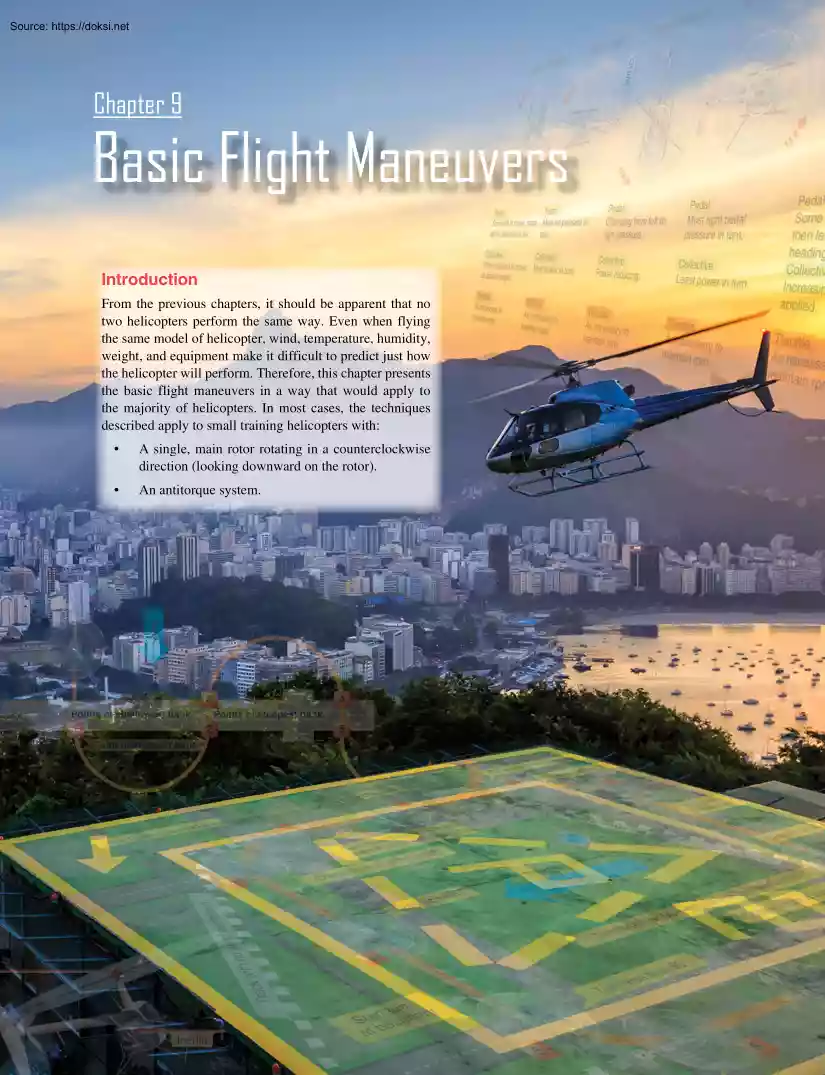
Chapter 9 Basic Flight Maneuvers Introduction From the previous chapters, it should be apparent that no two helicopters perform the same way. Even when flying the same model of helicopter, wind, temperature, humidity, weight, and equipment make it difficult to predict just how the helicopter will perform. Therefore, this chapter presents the basic flight maneuvers in a way that would apply to the majority of helicopters. In most cases, the techniques described apply to small training helicopters with: • A single, main rotor rotating in a counterclockwise direction (looking downward on the rotor). • An antitorque system. 9-1 Where a technique differs, it is noted. For example, a power increase on a helicopter with a clockwise rotor system requires right antitorque pedal pressure instead of left pedal pressure. In many cases, the terminology “apply proper pedal pressure” is used to indicate both types of rotor systems. However, when discussing throttle coordination
to maintain proper rotations per minute (rpm), there is no differentiation between those helicopters with a governor and those without. In a sense, the governor is doing the work for you. In addition, instead of using the terms “collective pitch control” and “cyclic pitch control” throughout the chapter, these controls are referred to as just “collective” and “cyclic.” Perform the maneuver with less intensity until all aspects of the machine can be controlled. The pilot must be aware of the sensitivity of the flight controls due to the high speed of the main rotor. 2. Anticipate changes in aircraft performance due to loading or environmental condition. The normal collective increase to check rotor speed at sea level standard (SLS) may not be sufficient at 4,000 feet pressure altitude (PA) and 95 °F. 3. The following flight characteristics may be expected during maneuvering flight and will be discussed and demonstrated by your Flight Instructor: Because
helicopter performance varies with weather conditions and aircraft loading, specific nose attitudes and power settings are not detailed in this handbook. In addition, this chapter does not detail every attitude of a helicopter in the various flight maneuvers, nor every move that must be made in order to perform a given maneuver. • Left turns, torque increases (more antitorque). This applies to most helicopters, but not all. • Right turns, torque decreases (less antitorque). This applies to most helicopters, but not all. • Application of aft cyclic, torque decreases and rotor speed increases. When a maneuver is presented, there is a brief description, followed by the technique to accomplish the maneuver. In most cases, there is a list of common errors at the end of the discussion. • Application of forward cyclic (especially when immediately following aft cyclic application), torque increases and rotor speed decreases. • Always leave a way out. The Four Fundamentals
• Know where the winds are. There are four fundamentals of flight upon which all maneuvers are based: straight-and-level flight, turns, climbs, and descents. All controlled flight maneuvers consist of one or more of these four fundamentals of flight. If a student pilot is able to perform these maneuvers well, and the student’s proficiency is based on accurate “feel” and control analysis rather than mechanical movements, the ability to perform any assigned maneuver is only a matter of obtaining a clear visual and mental conception of it. The flight instructor must impart a good knowledge of these basic elements to the student and must combine them and plan their practice so that proper performance of each is instinctive without conscious effort. The importance of this to the success of flight training cannot be overemphasized. As the student progresses to more complex maneuvers, discounting any difficulties in visualizing the maneuvers, most student difficulties are caused by
a lack of training, practice, or understanding of the principles of one or more of these fundamentals. • Engine failures can occur during power changes and cruise flight. One possible cause of engine failure during cruise flight can be attributed to the pilot ignoring carburetor air temperatures, which could lead to carburetor icing and, subsequently, engine failure. • Crew coordination is critical. Everyone needs to be fully aware of what is going on, and each crewmember has a specific duty. • In steep turns, the nose drops. In most cases, energy (airspeed) must be traded to maintain altitude as the required excess engine power may not be available (to maintain airspeed in a 2G/60° turn, rotor thrust/engine power must increase by 100 percent). Failure to anticipate this at low altitude endangers the crew and passengers. The rate of pitch change is proportional to gross weight and density altitude. Guidelines Good practices to follow during maneuvering flight include:
• Normal helicopter landings usually require high power settings, with terminations to a hover requiring the highest power setting. • The cyclic position relative to the horizon determines the helicopter’s travel and attitude. 1. 9-2 Move the cyclic only as fast as trim, torque, and rotor speed can be maintained. When entering a maneuver and the trim, rotor, or torque reacts quicker than anticipated, pilot limitations have been exceeded. If continued, an aircraft limitation will be exceeded. Straight-and-Level Flight Straight-and-level flight is flight in which constant altitude and heading are maintained. The attitude of the rotor disk relative to the horizon determines the airspeed. The horizontal stabilizer design determines the helicopter’s attitude when stabilized at an airspeed and altitude. Altitude is primarily controlled by use of the collective. Technique To maintain forward flight, the rotor tip-path plane must be tilted forward to obtain the necessary
horizontal thrust component from the main rotor. By doing this, it causes the nose of the helicopter to lower which in turn will cause the airspeed to increase. In order to counteract this, the pilot must find the correct power setting to maintain level flight by adjusting the collective. [Figure 9-1] The horizontal stabilizer aids in trimming the helicopter about its transverse, horizontal axis, and reduces the amount of nose tuck that would occur. On several helicopters, it is designed as a negative lift airfoil, which produces a lifting force in a downward direction. When in straight-and-level flight, any increase in the collective, while holding airspeed constant, causes the helicopter to climb. A decrease in the collective, while holding airspeed constant, causes the helicopter to descend. A change in the collective requires a coordinated change of the throttle to maintain a constant rpm. Additionally, the antitorque pedals need to keep the helicopter in trim around the vertical
axis. To increase airspeed in straight-and-level flight, apply forward pressure on the cyclic and raise the collective as necessary to maintain altitude. To decrease airspeed, apply rearward pressure on the cyclic and lower the collective, as necessary, to maintain altitude. A MR TEMP CLUTCH KNOTS 20 90 90 lOW FUEL LOW RPM 70 20 I0 I0 I0 I0 20 60 8 7 20 STBY PWR R 30 30 0 I ALT 2 29.8 29.9 30.0 3 5 4 I0 5 UP 15 VERTICAL SPEED 100 FEET PER MINUTE 20 DOWN 3 2 MIN TURN 9 0 CALIBRATED TO 20,000 FEET 6 TEST 24 35 DC FEET I00 20 50 60 80 70 L 25 MANFOLD PRESS IN H g AL g. TR CHIP 50 100 80 40 33 5 20 M STARTER ON 30 30 40 2I 15 20 MPH I5 80 70 60 50 120 110 I2 80 70 60 50 100 5 6 110 100 90 %RPM 10 O MR CHIP 0 R 10 E 110 100 90 15 I0 ELEC N 33 3 30 6 W 24 20 26 R I G H T OBS NAV 21 R E S S S 26 I00 P 15 FUEL II5 12 245 T E M P E GS Figure 9-1. Maintain straight-and-level flight by
adjusting the rotor tip-path plane forward but adjusting the collective as necessary to maintain a constant airspeed and altitude. The natural horizon line can be used as an aid in maintaining straight-and-level flight. If the horizon line begins to rise, slight power may be required or the nose of the helicopter may be too low. If the horizon line is slowly dropping, some power may need to be taken out or the nose of the helicopter may be too high, requiring a cyclic adjustment. Although the cyclic is sensitive, there is a slight delay in control reaction, and it is necessary to anticipate actual movement of the helicopter. When making cyclic inputs to control the altitude or airspeed of a helicopter, take care not to overcontrol. If the nose of the helicopter rises above the level-flight attitude, apply forward pressure to the cyclic to bring the nose down. If this correction is held too long, the nose drops too low. Since the helicopter continues to change attitude momentarily
after the controls reach neutral, return the cyclic to neutral slightly before the desired attitude is reached. This principle holds true for any cyclic input Since helicopters are not very stable, but are inherently very controllable, if a gust or turbulence causes the nose to drop, the nose tends to continue to drop instead of returning to a straight-and-level attitude as it would on a fixed-wing aircraft. Therefore, a pilot must remain alert and fly the helicopter at all times. Common Errors 1. Failure to trim the helicopter properly, tending to hold antitorque pedal pressure and opposite cyclic. This is commonly called cross-controlling. 2. Failure to maintain desired airspeed. 3. Failure to hold proper control position to maintain desired ground track. 4. Failure to allow helicopter to stabilize at new airspeed. Turns A turn is a maneuver used to change the heading of the helicopter. The aerodynamics of a turn were previously discussed in Chapter 2, Aerodynamics of
Flight. Technique Before beginning any turn, the area in the direction of the turn must be cleared not only at the helicopter’s altitude, but also above and below. To enter a turn from straight-and-level flight, apply sideward pressure on the cyclic in the direction the turn is to be made. This is the only control movement needed to start the turn. Do not use the pedals to assist the turn. Use the pedals only to compensate for torque to keep the helicopter in trim around the vertical axis. [Figure 9-2] Keeping the fuselage in the correct streamlined position around the vertical axis facilitates the helicopter flying forward with the least drag. Trim is indicated by a yaw string in the center, or a centered ball on a turn and slip indicator. A yaw string (also referred to as a slip string) is a tool used to indicate slip or skid during flight. It is simply a string attached to the nose or canopy of an aircraft so that it is visible to the pilot during flight. The string measures
sideslip and offers a visual cue to the pilot in order to make yaw corrections. 9-3 or too much in the direction opposite the turn, in relation to the amount of power used. In other words, if you hold improper antitorque pedal pressure, which keeps the nose from following the turn, the helicopter slips sideways toward the center of the turn. Inertia HCL Figure 9-2. During a level, coordinated turn, the rate of turn is commensurate with the angle of bank used, and inertia and horizontal component of lift (HCL) are equal. How fast the helicopter banks depends on how much lateral cyclic pressure is applied. How far the helicopter banks (the steepness of the bank) depends on how long the cyclic is displaced. After establishing the proper bank angle, return the cyclic toward the neutral position. When the bank is established, returning the cyclic to neutral (or holding it inclined relative to the horizon) will maintain the helicopter at that bank angle. Increase the collective
and throttle to maintain altitude and rpm. As the torque increases, increase the proper antitorque pedal pressure to maintain longitudinal trim. Depending on the degree of bank, additional forward cyclic pressure may be required to maintain airspeed. Skids A skid occurs when the helicopter slides sideways away from the center of the turn. [Figure 9-4] It is caused by too much antitorque pedal pressure in the direction of the turn, or by too little in the direction opposite the turn in relation to the amount of power used. If the helicopter is forced to turn faster with increased pedal pressure instead of by increasing the degree of the bank, it skids sideways away from the center of the turn instead of flying in its normal curved path. In summary, a skid occurs when the rate of turn is too great for the amount of bank being used, and a slip occurs when the rate of turn is too low for the amount of bank being used. [Figure 9-5] Slip HCL Inertia Rolling out of the turn to
straight-and-level flight is the same as the entry into the turn, except that pressure on the cyclic is applied in the opposite direction. Since the helicopter continues to turn as long as there is any bank, start the rollout before reaching the desired heading. The discussion on level turns is equally applicable to making turns while climbing or descending. The only difference is that the helicopter is in a climbing or descending attitude rather than that of level flight. If a so-called simultaneous entry (entering a turn while, at the same time, climbing or descending) is desired, merely combine the techniques of both maneuversclimb or descent entry and turn entry. When recovering from a climbing or descending turn, the desired heading and altitude are rarely reached at the same time. If the heading is reached first, stop the turn and maintain the climb or descent until reaching the desired altitude. On the other hand, if the altitude is reached first, establish the level flight
attitude and continue the turn to the desired heading. Slips A slip occurs when the helicopter slides sideways toward the center of the turn. [Figure 9-3] It is caused by an insufficient amount of antitorque pedal in the direction of the turn, 9-4 Figure 9-3. During a slip, the rate of turn is too low for the angle of bank used, and the horizontal component of lift (HCL) exceeds inertia. Skid HCL Inertia Figure 9-4. During a skid, the rate of turn is too great for the angle of bank used, and inertia exceeds the horizontal component of lift (HCL). Slip Yaw string 0 SA 4 6 8 knots 50 8 6 NET knots 120 80 100 20 70 GO FEET I00 9 0 FNCN AVG + L NAV PULL 160 140 10 60 H OFF 60 40 10 winter 4 90 kno ts 2 2 -4 PUS ALT 8 VOL BATT PWR DIST PUSH O LT 0 10 -2 80 Acceleration 8 G UNITS 10 6 4 2 0 KNOTS − HW 7 SEL PUS 6 FOR N 30 S 210 240 60 E 120 150 300 330 STEER I ALT CALIBRATED TO 20,000 FEET 2 29.8 29.9 30.0 3
5 4 H FOR W STEER ON ON RADIO Coordinated Yaw string 0 2 2 50 -2 4 -4 6 8 4 knots 8 6 60 40 10 winter 160 knots 140 10 120 80 100 20 60 PUS H 70 GO NET FEET I00 9 0 FNCN AVG + L NAV PULL ALT 8 VOL BATT PWR DIST PUSH O LT 0 90 SA 10 kno ts Acceleration 8 G UNITS 80 2 0 10 6 4 OFF KNOTS − HW 7 SEL PUS 6 FOR N 30 S 210 240 60 E 120 150 300 330 STEER I ALT CALIBRATED TO 20,000 FEET 2 29.8 29.9 30.0 3 5 4 H FOR W STEER ON ON RADIO Skid Yaw string 0 2 50 -4 8 8 6 40 10 knots winter 4 To begin the level-off, apply forward cyclic to adjust and maintain a level flight attitude, which can be slightly nose low. Maintain climb power until the airspeed approaches the desired cruising airspeed, then lower the collective to obtain cruising power and adjust the throttle to obtain and maintain cruising rpm. Throughout the level-off, maintain longitudinal trim with the antitorque pedals. knots 120
80 I00 + L NAV KNOTS 8 VOL BATT PWR − 7 SEL PUS H 1. Failure to maintain proper power and airspeed. 2. Holding too much or too little antitorque pedal. 3. In the level-off, decreasing power before adjusting the nose to cruising attitude. 100 20 FNCN AVG DIST ALT 160 140 10 70 GO NET HW 60 60 H PUSH 2 0 10 -2 6 90 SA kno ts Acceleration 8 G UNITS 4 80 2 0 O LT 10 6 PUS PULL To level off from a climb, start adjusting the attitude to the level flight attitude a few feet prior to reaching the desired altitude. The amount of lead depends on the rate of climb at the time of level-off (the higher the rate of climb, the more the lead). Generally, the lead is 10 percent of the climb rate For example, if the climb rate is 500 feet per minute (fpm), you should lead the level-off by 50 feet. Common Errors 4 OFF If the pilot wishes to climb faster, with a decreased airspeed, then the climb can be initiated with aft cyclic. Depending on initial or
entry airspeed for the climb, the climb can be accomplished without increasing the collective, if a much slower airspeed is acceptable. However, as the airspeed decreases, the airflow over the vertical fin decreases necessitating more antitorque (left) pedal application. FEET 9 0 CALIBRATED TO 20,000 FEET 6 FOR I ALT 5 4 N 30 S 210 240 60 E 120 150 300 330 STEER 2 29.8 29.9 30.0 3 FOR W STEER ON ON RADIO Figure 9-5. Cockpit view of a slip and skid Normal Climb The entry into a climb from a hover has already been described in the Normal Takeoff from a Hover subsection; therefore, this discussion is limited to a climb entry from cruising flight. Technique To enter a climb in a helicopter while maintaining airspeed, the first actions are increasing the collective and throttle, and adjusting the pedals as necessary to maintain a centered ball in the slip/skid indicator. Moving the collective up requires a slight aft movement of the cyclic to direct all of the
increased power into lift and maintain the airspeed. Remember, a helicopter can climb with the nose down and descend with the nose up. Helicopter attitude changes mainly reflect acceleration or deceleration, not climb or descent. Therefore, the climb attitude is approximately the same as level flight in a stable climb, depending on the aircraft’s horizontal stabilizer design. Normal Descent A normal descent is a maneuver in which the helicopter loses altitude at a controlled rate in a controlled attitude. Technique To establish a normal descent from straight-and-level flight at cruising airspeed, lower the collective to obtain proper power, adjust the throttle to maintain rpm, and increase right antitorque pedal pressure to maintain heading in a counterclockwise rotor system (or left pedal pressure in a clockwise system). If cruising airspeed is the same as or slightly above descending airspeed, simultaneously apply the necessary cyclic pressure to obtain the approximate
descending attitude. If the pilot wants to decelerate, the cyclic must be moved aft. If the pilot desires to descend with increased airspeed, then forward cyclic is all that is required if airspeed remains under the limit. As the helicopter stabilizes at any forward airspeed, the fuselage attitude will streamline due to the airflow over the horizontal stabilizer. As the airspeed changes, the airflow over the vertical stabilizer or fin changes, so the pedals must be adjusted for trim. 9-5 The pilot should always remember that the total lift and thrust vectoring is controlled by the cyclic. If a certain airspeed is desired, it will require a certain amount of cyclic and collective movement for level flight. If the cyclic is moved, the thrust-versus-lift ratio is changed. Aft cyclic directs more power to lift, and altitude increases. Forward cyclic directs more power to thrust, and airspeed increases. If the collective is not changed and there is a change only in cyclic, the total
thrust to lift ratio does not change: aft cyclic results in a climb, and forward cyclic results in a descent with the corresponding airspeed changes. To level off from the descent, lead the desired altitude by approximately 10 percent of the rate of descent. For example, a 500-fpm rate of descent would require a 50-foot lead. At this point, increase the collective to obtain cruising power, adjust the throttle to maintain rpm, and increase left antitorque pedal pressure to maintain heading (right pedal pressure in a clockwise rotor system). Adjust the cyclic to obtain cruising airspeed and a level flight attitude as the desired altitude is reached. Common Errors 1. Failure to maintain constant angle of decent during training. 2. Failure to level-off the aircraft sufficiently, which results in recovery below the desired altitude. 3. Failure to adjust antitorque pedal pressures for changes in power. Vertical Takeoff to a Hover A vertical takeoff to a hover involves flying the
helicopter from the ground vertically to a skid height of two to three feet, while maintaining a constant heading. Once the desired skid height is achieved, the helicopter should remain nearly motionless over a reference point at a constant altitude and on a constant heading. The maneuver requires a high degree of concentration and coordination. Technique The pilot on the controls needs to clear the area left, right, and above to perform a vertical takeoff to a hover. The pilot should remain focused outside the aircraft and obtain clearance to take off from the controlling tower. If necessary, the pilot who is not on the controls assists in clearing the aircraft and provides adequate warning of any obstacles and any unannounced or unusual drift/altitude changes. Heading control, direction of turn, and rate of turn at hover are all controlled by using the pedals. Hover height, rate of ascent, and the rate of descent are controlled by using the 9-6 collective. Helicopter position and
the direction of travel are controlled by the cyclic. After receiving the proper clearance and ensuring that the area is clear of obstacles and traffic, begin the maneuver with the collective in the down position and the cyclic in a neutral position, or slightly into the wind. Very slowly increase the collective until the helicopter becomes light on the skids or wheels. As collective and torque increases, antitorque must be adjusted as well. Therefore, as the aircraft begins to get light on the landing gear, apply appropriate antitorque pedal to maintain aircraft heading. Continue to apply pedals as necessary to maintain heading and coordinate the cyclic for a vertical ascent. As the helicopter slowly leaves the ground, check for proper attitude control response and helicopter center of gravity. A slow ascent will allow stopping if responses are outside the normal parameters indicating hung or entangled landing gear, center of gravity problems, or control issues. If a roll or tilt
begin, decrease the collective and determine the cause of the roll or tilt. Upon reaching the desired hover altitude, adjust the flight controls as necessary to maintain position over the intended hover area. Student pilots should be reminded that while at a hover, the helicopter is rarely ever level. Helicopters usually hover left side low due to the tail rotor thrust being counteracted by the main rotor tilt. A nose low or high condition is generally caused by loading. Once stabilized, check the engine instruments and note the power required to hover. Excessive movement of any flight control requires a change in the other flight controls. For example, if the helicopter drifts to one side while hovering, the pilot naturally moves the cyclic in the opposite direction. When this is done, part of the vertical thrust is diverted, resulting in a loss of altitude. To maintain altitude, increase the collective This increases drag on the blades and tends to slow them down. To counteract the
drag and maintain rpm, increase the throttle. Increased throttle means increased torque, so the pilot must add more pedal pressure to maintain the heading. This can easily lead to overcontrolling the helicopter. However, as level of proficiency increases, problems associated with overcontrolling decrease. Helicopter controls are usually more driven by pressure than by gross control movements. Common Errors 1. Failing to ascend vertically as the helicopter becomes airborne. 2. Pulling excessive collective to become airborne, causing the helicopter to gain too much altitude. 3. Overcontrolling the antitorque pedals, which not only changes the heading of the helicopter, but also changes the rpm. 4. 5. Reducing throttle rapidly in situations in which proper rpm has been exceeded, usually resulting in exaggerated heading changes and loss of lift, resulting in loss of altitude. 3. Confusing attitude changes for altitude changes, which results in improper use of the controls.
4. Hovering too high, creating a hazardous flight condition. The height velocity chart should be referenced to determine the maximum skid height to hover and safely recover the helicopter should a malfunction occur. 5. Hovering too low, resulting in occasional touchdown. 6. Becoming overly confident over prepared surfaces when taking off to a hover. Be aware that dynamic rollover accidents usually occur over a level surface. Failing to ascend slowly. Hovering A stationary hover is a maneuver in which the helicopter is maintained in nearly motionless flight over a reference point at a constant altitude and on a constant heading. Technique To maintain a hover over a point, use sideview and peripheral vision to look for small changes in the helicopter’s attitude and altitude. When these changes are noted, make the necessary control inputs before the helicopter starts to move from the point. To detect small variations in altitude or position, the main area of visual
attention needs to be some distance from the aircraft, using various points on the helicopter or the tip-path plane as a reference. Looking too closely or looking down leads to overcontrolling. Obviously, in order to remain over a certain point, know where the point is, but do not focus all attention there. As with a takeoff, the pilot controls altitude with the collec tive and maintains a constant rpm with the throttle. The cyclic is used to maintain the helicopter’s position; the pedals, to control heading. To maintain the helicopter in a stabilized hover, make small, smooth, coordinated corrections. As the desired effect occurs, remove the correction in order to stop the helicopter’s movement. For example, if the helicopter begins to move rearward, apply a small amount of forward cyclic pressure. However, neutralize this pressure just before the helicopter comes to a stop, or it will begin to move forward. After experience is gained, a pilot develops a certain “feel” for
the helicopter. Small deviations can be felt and seen, so you can make the corrections before the helicopter actually moves. A certain relaxed looseness develops, and controlling the helicopter becomes second nature, rather than a mechanical response. Common Errors 1. Tenseness and slow reactions to movements of the helicopter. 2. Failure to allow for lag in cyclic and collective pitch, which leads to overcontrolling. It is very common for a student to get ahead of the helicopter. Due to inertia, it requires some small time period for the helicopter to respond. Hovering Turn A hovering turn is a maneuver performed at hovering height in which the nose of the helicopter is rotated either left or right while maintaining position over a reference point on the surface. Hovering turns can also be made around the mast or tail of the aircraft. The maneuver requires the coordination of all flight controls and demands precise control near the surface. A pilot should maintain a constant
altitude, rate of turn, and rpm. Technique Initiate the turn in either direction by applying anti-torque pedal pressure toward the desired direction. It should be noted that during a turn to the left, more power is required because left pedal pressure increases the pitch angle of the tail rotor, which, in turn, requires additional power from the engine. A turn to the right requires less power. (On helicopters with a clockwise rotating main rotor, right pedal increases the pitch angle and, therefore, requires more power.) As the turn begins, use the cyclic as necessary (usually into the wind) to keep the helicopter over the desired spot. To continue the turn, add more pedal pressure as the helicopter turns to the crosswind position. This is because the wind is striking the tail surface and tail rotor area, making it more difficult for the tail to turn into the wind. As pedal pressures increase due to crosswind forces, increase the cyclic pressure into the wind to maintain position.
Use the collective with the throttle to maintain a constant altitude and rpm. [Figure 9-6] After the 90° portion of the turn, decrease pedal pressure slightly to maintain the same rate of turn. Approaching the 180°, or downwind portion, anticipate opposite pedal pressure due to the tail moving from an upwind position to a down wind position. At this point, the rate of turn has a tendency to increase at a rapid rate due to the tendency of the tail surfaces to weathervane. Because of the tailwind condition, 9-7 CyclicRight CyclicRearward CyclicLeft CyclicForward WIND WIND CyclicForward Pedal Some left in hover, more left to start turn to left Pedal Most left pressure in turn Pedal Changing from left to right pressure Pedal Most right pedal pressure in turn Pedal Some right to stop turn, then left to maintain heading Collective Adjust collective as necessary to maintain proper hover height Collective Adjust collective as necessary to maintain proper hover height
Collective Adjust collective as necessary to maintain proper hover height Collective Adjust collective as necessary to maintain proper hover height Collective Adjust collective as necessary to maintain proper hover height Throttle As necessary to maintain rpm Throttle As necessary to maintain rpm Throttle As necessary to maintain rpm Throttle As necessary to maintain rpm Throttle As necessary to maintain rpm Normally left pedal application requires more throttle Normally left pedal application requires more throttle Normally left pedal application requires more throttle Normally left pedal application requires more throttle Figure 9-6. Left turns in helicopters with a counterclockwise rotating main rotor are more difficult to execute because the tail rotor demands more power. This requires you to compensate with additional left pedal and increased throttle Refer to this graphic throughout the remainder of the discussion on a hovering turn to the left. hold rearward cyclic
pressure to keep the helicopter over the same spot. The horizontal stabilizer has a tendency to lift the tail during a tailwind condition. This is the most difficult portion of the hovering turn. Horizontal and vertical stabilizers have several different designs and locations, including the canted stabilizers used on some Hughes and Schweizer helicopters. The primary purpose of the vertical stabilizer is to unload the work of the antitorque system and to aid in trimming the helicopter in flight should the antitorque system fail. The horizontal stabilizer provides for a more usable CG range and aids in trimming the helicopter longitudinally. Because of the helicopter’s tendency to weathervane, maintaining the same rate of turn from the 180° position actually requires some pedal pressure opposite the direction of turn. If a pilot does not apply opposite pedal pressure, the helicopter tends to turn at a faster rate. The amount of pedal pressure and cyclic deflection throughout the
turn depends on the wind velocity. As the turn is finished on the upwind heading, apply opposite pedal pressure to stop the turn. Gradually apply forward cyclic pressure to keep the helicopter from drifting. 9-8 Control pressures and direction of application change continuously throughout the turn. The most dramatic change is the pedal pressure (and corresponding power requirement) necessary to control the rate of turn as the helicopter moves through the downwind portion of the maneuver. Turns can be made in either direction; however, in a high wind condition, the tail rotor may not be able to produce enough thrust, which means the pilot cannot control a turn to the right in a counterclockwise rotor system. Therefore, if control is ever questionable, first attempt to make a 90° turn to the left. If sufficient tail rotor thrust exists to turn the helicopter crosswind in a left turn, a right turn can be successfully controlled. The opposite applies to helicopters with clockwise
rotor systems. In this case, start the turn to the right. Hovering turns should be avoided in winds strong enough to preclude sufficient aft cyclic control to maintain the helicopter on the selected surface reference point when headed downwind. Check the flight manual for the manufacturer’s recommendations for this limitation. Common Errors 1. Failing to maintain a slow, constant rate of turn. 2. Failing to maintain position over the reference point. 3. Failing to maintain rpm within normal range. 4. Failing to maintain constant altitude. 5. Failing to use the antitorque pedals properly. HoveringForward Flight Forward hovering flight is normally used to move a helicopter to a specific location, and it may begin from a stationary hover. During the maneuver, constant groundspeed, altitude, and heading should be maintained. Technique Before starting, pick out two references directly in front and in line with the helicopter. These reference points should be kept in line
throughout the maneuver. [Figure 9-7] Begin the maneuver from a normal hovering height by applying forward pressure on the cyclic. As movement begins, return the cyclic toward the neutral position to maintain low groundspeedno faster than a brisk walk. Throughout the maneuver, maintain a constant groundspeed and path over the ground with the cyclic, a constant heading with the antitorque pedals, altitude with the collective, and the proper rpm with the throttle. To stop the forward movement, apply rearward cyclic pressure until the helicopter stops. As forward motion stops, return the cyclic to the neutral position to prevent rearward movement. Forward movement can also be stopped by simply applying rearward pressure to level the helicopter and allowing it to drift to a stop. 2. Failure to use proper antitorque pedal control, resulting in excessive heading change. 3. Failure to maintain desired hovering height. 4. Failure to maintain proper rpm. 5. Failure to maintain
alignment with direction of travel. HoveringSideward Flight Sideward hovering flight may be necessary to move the helicopter to a specific area when conditions make it impossible to use forward flight. During the maneuver, a constant groundspeed, altitude, and heading should be maintained. Technique Before starting sideward hovering flight, ensure the area for the hover is clear, especially at the tail rotor. Constantly monitor hover height and tail rotor clearance during all hovering maneuvers to prevent dynamic rollover or tail rotor strikes to the ground. Then, pick two points of in-line reference in the direction of sideward hovering flight to help maintain the proper ground track. These reference points should be kept in line throughout the maneuver. [Figure 9-8] Begin the maneuver from a normal hovering height by applying cyclic toward the side in which the movement is desired. As the movement begins, return the cyclic toward the neutral position to maintain low groundspeedno
faster than a brisk walk. Throughout the maneuver, maintain a constant groundspeed and ground track with cyclic. Maintain heading, Common Errors 1. Exaggerated movement of the cyclic, resulting in erratic movement over the surface. Reference point Reference point A MR TEMP CLUTCH KNOTS 20 100 110 100 90 90 80 70 60 50 90 20 MPH 30 30 40 40 20 50 50 70 20 I0 I0 I0 I0 20 60 R 8 7 20 STBY PWR 30 2I 35 I ALT 2 29.8 29.9 30.0 3 5 4 I0 5 UP 0 15 VERTICAL SPEED 100 FEET PER MINUTE 20 DOWN 3 2 MIN TURN 9 0 CALIBRATED TO 20,000 FEET 6 TEST 24 30 DC FEET I00 60 80 70 L 25 MANFOLD PRESS IN H g AL g. LOW RPM 33 5 lOW FUEL I5 15 10 120 110 100 80 %RPM 20 TR CHIP I2 80 70 60 50 M STARTER ON 5 6 110 100 90 O MR CHIP 0 R 10 E 15 I0 ELEC N 33 3 30 6 W 24 20 26 R I G H T OBS NAV 21 R E S S S 26 I00 P 15 FUEL II5 12 245 T E M P E GS Figure 9-7. To maintain a straight ground track, use two
reference points in line and at some distance in front of the helicopter. Figure 9-8. The key to hovering sideward is establishing at least two reference points that help maintain a straight track over the ground while keeping a constant heading. 9-9 which in this maneuver is perpendicular to the ground track, with the antitorque pedals, and a constant altitude with the collective. Use the throttle to maintain the proper operating rpm. Be aware that the nose tends to weathervane into the wind. Changes in the pedal position will change the rpm and must be corrected by collective and/or throttle changes to maintain altitude. To stop the rearward movement, apply forward cyclic and hold it until the helicopter stops. As the motion stops, return the cyclic to the neutral position. Also, as in the case of forward and sideward hovering flight, opposite cyclic can be used to level the helicopter and let it drift to a stop. Tail rotor clearance must be maintained. Generally, a
higher-thannormal hover altitude is preferred To stop the sideward movement, apply cyclic pressure in the direction opposite to that of movement and hold it until the helicopter stops. As motion stops, return the cyclic to the neutral position to prevent movement in the opposite direction. Applying sufficient opposite cyclic pressure to level the helicopter may also stop sideward movement. The helicopter then drifts to a stop. Common Errors Common Errors 1. Exaggerated movement of the cyclic, resulting in overcontrolling and erratic movement over the surface. 2. Failure to use proper antitorque pedal control, resulting in excessive heading change. 3. Failure to maintain desired hovering height. 4. Failure to maintain proper rpm. 5. Failure to make sure the area is clear prior to starting the maneuver. HoveringRearward Flight Rearward hovering flight may be necessary to move the helicopter to a specific area when the situation is such that forward or sideward hovering
flight cannot be used. During the maneuver, maintain a constant groundspeed, altitude, and heading. Due to the limited visibility behind a helicopter, it is important that the area behind the helicopter be cleared before beginning the maneuver. Use of ground personnel is recommended. Technique Before starting rearward hovering flight, pick out two reference points in front of, and in line with the helicopter just like hovering forward. [Figure 9-7] The movement of the helicopter should be such that these points remain in line. Begin the maneuver from a normal hovering height by applying rearward pressure on the cyclic. After the movement has begun, position the cyclic to maintain a slow groundspeedno faster than a brisk walk. Throughout the maneuver, maintain constant groundspeed and ground track with the cyclic, a constant heading with the antitorque pedals, constant altitude with the collective, and the proper rpm with the throttle. 1. Exaggerated movement of the cyclic
resulting in overcontrolling and an uneven movement over the surface. 2. Failure to use proper antitorque pedal control, resulting in excessive heading change. 3. Failure to maintain desired hovering height. 4. Failure to maintain proper rpm. 5. Failure to make sure the area is clear prior to starting the maneuver. Taxiing Taxiing refers to operations on or near the surface of taxiways or other prescribed routes. Helicopters utilize three different types of taxiing. Hover Taxi A hover taxi is used when operating below 25 feet above ground level (AGL). [Figure 9-9] Since hover taxi is just like forward, sideward, or rearward hovering flight, the technique to perform it is not presented here. Air Taxi An air taxi is preferred when movements require greater distances within an airport or heliport boundary. [Figure 9-10] In this case, fly to the new location; however, it is expected that the helicopter will remain below 100 feet AGL with an appropriate airspeed and will avoid
over flight of other aircraft, vehicles, and personnel. Hover taxi (25 feet or less) Poor surface conditions for skid type helicopters Figure 9-9. Hover taxi 9-10 Air taxi (100 feet or less) 6. Flying in the cross-hatched or shaded area of the height/velocity diagram. 7. Flying in a crosswind that could lead to loss of tail rotor effectiveness. 8. Excessive tail-low attitudes. 9. Excessive power used or required to stop. 10. Failure to maintain alignment with direction of travel Faster travel Figure 9-10. Air taxi Technique Before starting, determine the appropriate airspeed and altitude combination to remain out of the cross-hatched or shaded areas of the height/velocity diagram (see Figure 7-1). Additionally, be aware of crosswind conditions that could lead to loss of tail rotor effectiveness. Pick out two references directly in front of the helicopter for the ground path desired. These reference points should be kept in line throughout the maneuver. Begin the
maneuver from a normal hovering height by applying forward pressure on the cyclic. As movement begins, attain the desired airspeed with the cyclic. Control the desired altitude with the collective and rpm with the throttle. Throughout the maneuver, maintain a desired groundspeed and ground track with the cyclic, a constant heading with antitorque pedals, the desired altitude with the collective, and proper operating rpm with the throttle. To stop the forward movement, apply aft cyclic pressure to reduce forward speed. Simultaneously lower the collective to initiate a descent to hover altitude. As forward motion stops, return the cyclic to the neutral position to prevent rearward movement. As approaching the proper hover altitude, increase the collective as necessary to stop descent at hover altitude (much like a quick stop maneuver (see page 10-4)). Surface Taxi A surface taxi is used to minimize the effects of rotor downwash in wheel-type helicopters. [Figure 9-11] Surface
taxiing in skid type helicopters is generally not recommended due to the high risk of dynamic rollover; for more information, refer to Chapter 11, Helicopter Emergencies and Hazards. Technique The helicopter should be in a stationary position on the surface with the collective full down and the rpm the same as that used for a hover. This rpm should be maintained throughout the maneuver. Then, move the cyclic slightly forward and apply gradual upward pressure on the collective to move the helicopter forward along the surface. Use the antitorque pedals to maintain heading and the cyclic to maintain ground track. The collective controls starting, stopping, and speed while taxiing. The higher the collective pitch, the faster the taxi speed; however, do not taxi faster than a brisk walk. If the helicopter is equipped with brakes, use them to help slow down. Do not use the cyclic to control groundspeed During a crosswind taxi, hold the cyclic into the wind a sufficient amount to eliminate
any drifting movement. Common Errors 1. Improper use of cyclic. 2. Failure to use antitorque pedals for heading control. Surface taxi Common Errors 1. Erratic movement of the cyclic, resulting in improper airspeed control and erratic movement over the surface. 2. Failure to use proper antitorque pedal control, resulting in excessive heading change. 3. Failure to maintain desired altitude. 4. Failure to maintain proper rpm. 5. Overflying parked aircraft causing possible damage from rotor downwash. Less rotor downwash Figure 9-11. Surface taxi 9-11 3. Improper use of the controls during crosswind operations. 4. Failure to maintain proper rpm. While accelerating through effective translational lift (position 3), the helicopter begins to climb, and the nose tends to rise due to increased lift. At this point, adjust the collective to obtain normal climb power and apply enough forward cyclic to overcome the tendency of the nose to rise. At position 4, hold an
attitude that allows a smooth acceleration toward climbing airspeed and a commensurate gain in altitude so that the takeoff profile does not take the helicopter through any of the cross-hatched or shaded areas of the height/velocity diagram. As airspeed increases (position 5), place the aircraft in trim and allow a crab to take place to maintain ground track and a more favorable climb configuration. As the helicopter continues to climb and accelerate to best rate-of-climb, apply aft cyclic pressure to raise the nose smoothly to the normal climb attitude. Normal Takeoff from a Hover A normal takeoff from a hover is an orderly transition to forward flight and is executed to increase altitude safely and expeditiously. Before initiating a takeoff, the pilot should ensure that the proper checklist has been completed and the helicopter systems are within normal limits. During the takeoff, fly a profile that avoids the cross-hatched or shaded areas of the height/velocity diagram.
Technique Refer to Figure 9-12 (position 1). Bring the helicopter to a hover and perform a hover and systems check, which includes power, balance, and flight controls prior to continuing flight. The power check should include an evaluation of the amount of excess power available; that is, the difference between the power being used to hover and the power available at the existing altitude and temperature conditions. The balance condition of the helicopter is indicated by the position of the cyclic when maintaining a stationary hover. Wind necessitates some cyclic deflection, but there should not be an extreme deviation from neutral. Flight controls must move freely, and the helicopter should respond normally. Then, visually clear the surrounding area. Common Errors Start the helicopter moving by smoothly and slowly easing the cyclic forward (position 2). As the helicopter starts to move forward, increase the collective, as necessary, to prevent the helicopter from sinking and
adjust the throttle to maintain rpm. The increase in power requires an increase in the proper antitorque pedal to maintain heading. Maintain a straight takeoff path throughout the takeoff. 1. Failing to use sufficient collective pitch to prevent loss of altitude prior to attaining translational lift. 2. Adding power too rapidly at the beginning of the transition from hovering to forward flight without forward cyclic compensation, causing the helicopter to gain excessive altitude before acquiring airspeed. 3. Assuming an extreme nose-down attitude near the surface in the transition from hovering to forward flight. 4. Failing to maintain a straight flightpath over the surface (ground track). 5. Failing to maintain proper airspeed during the climb. 6. Failing to adjust the throttle to maintain proper rpm. 7. Failing to transition to a level crab to maintain ground track. 5 4 3 1 2 Figure 9-12. The helicopter takes several positions during a normal takeoff from hover
9-12 Normal Takeoff from the Surface side opposite the cyclic. Normal takeoff from the surface is used to move the helicopter from a position on the surface into effective translational lift and a normal climb using a minimum amount of power. If the surface is dusty or covered with loose snow, this technique provides the most favorable visibility conditions and reduces the possibility of debris being ingested by the engine. After approximately 50 feet of altitude is gained, make a coordinated turn into the wind to maintain the desired ground track. This is called crabbing into the wind The stronger the crosswind, the more the helicopter has to be turned into the wind to maintain the desired ground track. [Figure 9-14] Technique Place the helicopter in a stationary position on the surface. Lower the collective to the full down position, and reduce the rpm below operating rpm. Visually clear the area and select terrain features or other objects to aid in maintaining the
desired track during takeoff and climb out. Increase the throttle to the proper rpm, and raise the collective slowly until the helicopter is light on the skids. Hesitate momentarily and adjust the cyclic and antitorque pedals, as necessary, to prevent any surface movement. Continue to apply upward collective. As the helicopter leaves the ground, use the cyclic, as necessary, to begin forward movement as altitude is gained. Continue to accelerate As effective translational lift is attained, the helicopter begins to climb. Adjust attitude and power, if necessary, to climb in the same manner as a takeoff from a hover. A second, less efficient, but acceptable, technique, is to attempt a vertical takeoff to evaluate if power or lift is sufficient to clear obstructions. This allows the helicopter to be returned to the takeoff position if required. Ground Reference Maneuvers Ground reference maneuvers may be used as training exercises to help develop a division of attention between the
flightpath and ground references, and while controlling Helicopter side movement Wind movement Figure 9-13. During a slip, the rotor disk is tilted into the wind Common Errors Ground Track ing 3. ead Using excessive power combined with a level attitude, which causes a vertical climb, unless needed for obstructions and landing considerations. ter H 2. cop Departing the surface in an attitude that is too noselow. This situation requires the use of excessive power to initiate a climb. Heli 1. Wind Movement Application of the collective that is too abrupt when departing the surface, causing rpm and heading control errors. Crosswind Considerations During Takeoffs If the takeoff is made during crosswind conditions, the helicopter is flown in a slip during the early stages of the maneuver. [Figure 9-13] The cyclic is held into the wind a sufficient amount to maintain the desired ground track for the takeoff. The heading is maintained with the use of the antitorque pedals.
In other words, the rotor is tilted into the wind so that the sideward movement of the helicopter is just enough to counteract the crosswind effect. To prevent the nose from turning in the direction of the rotor tilt, it is necessary to increase the antitorque pedal pressure on the Figure 9-14. To compensate for wind drift at altitude, crab the helicopter into the wind. 9-13 the helicopter and watching for other aircraft in the vicinity. Other examples of ground reference maneuvers are flights for photographic or observation purposes, such as pipe line or power line checks. Prior to each maneuver, a clearing turn should be done to ensure the area is free of conflicting traffic. line and maintain a specific heading, aircraft heading must be adjusted in order to compensate for the winds and stay on the proper ground track. Also, keep in mind that a constant scan of flight instruments and outside references aid in maintaining proper ground track. Rectangular Course The
rectangular course is a training maneuver in which the ground track of the helicopter is kept equidistant from the sides of a selected rectangular area. While performing the maneuver, the altitude and airspeed should be held constant. The rectangular course helps develop recognition of a drift toward or away from a line parallel to the intended ground track. This is helpful in recognizing drift toward or from an airport runway during the various legs of the airport traffic pattern and is also useful in observation and photographic flights. Although the rectangular course may be entered from any direction, this discussion assumes entry on a downwind heading. [Figure 9-15] while approaching the field boundary on the downwind leg, begin planning for an upcoming turn. Since there is a tailwind on the downwind leg, the helicopter’s groundspeed is increased (position 1). During the turn, the wind causes the helicopter to drift away from the field. To counteract this effect, the
roll-in should be made at a fairly fast rate with a relatively steep bank (position 2). This is normally the steepest turn of the maneuver. Technique Maintaining ground track while trying to fly a straight line can be very difficult for new pilots to do. It is important to understand the effects of the wind and how to compensate for this. For this maneuver, pick a square or rectangular field, or an area bounded on four sides by section lines or roads, with sides approximately a mile in length. The area selected should be well away from other air traffic. Fly the maneuver approximately 500 to 1,000 feet above the ground as appropriate. If the student finds it difficult to maintain a proper ground track at that higher altitude, lower the altitude for better ground reference until they feel more comfortable and are able to grasp the concept better. Altitude can be raised up to 1,000 feet as proficiency improves. Fly the helicopter parallel to and at a uniform distance, about one-fourth
to one-half mile, from the field boundaries, and not directly above the boundaries. For best results, position flightpath outside the field boundaries just far enough away that they may be easily observed from either pilot seat by looking out the side of the helicopter. If an attempt is made to fly directly above the edges of the field, there will be no usable reference points to start and complete the turns. In addition, the closer the track of the helicopter is to the field boundaries, the steeper the bank necessary at the turning points. The edges of the selected field should be seen while seated in a normal position and looking out the side of the helicopter during either a left-hand or right-hand course. The distance of the ground track from the edges of the field should be the same regardless of whether the course is flown to the left or right. All turns should be started when the helicopter is abeam the corners of the field boundaries. The bank normally should not exceed
30°–45° in light winds. Strong winds may require more bank. The pilot should understand that when trying to fly a straight 9-14 As the turn progresses, the tailwind component decreases, which decreases the groundspeed. Consequently, the bank angle and rate-of-turn must be reduced gradually to ensure that upon completion of the turn, the crosswind ground track continues to be the same distance from the edge of the field. Upon completion of the turn, the helicopter should be level and crabbed into the wind in order to maintain the proper ground track. Keep in mind that in order to maintain proper ground track the helicopter may have to be flown almost sideways depending on the amount of wind. The forward cyclic that is applied for airspeed will be in the direction of the intended flight path. For this example, it will be in the direction of the downwind corner of the field. However, since the wind is now pushing the helicopter away from the field, establish the proper drift
correction by heading slightly into the wind. Therefore, the turn should be greater than a 90° change in heading (position 3). If the turn has been made properly, the field boundary again appears to be one-fourth to one-half mile away. While on the crosswind leg, the wind correction should be adjusted, as necessary, to maintain a uniform distance from the field boundary (position 4). As the next field boundary is being approached (position 5), plan for the next turn. Since a wind correction angle is being held into the wind and toward the field, this next turn requires a turn of less than 90°. Since there is now a headwind, the groundspeed decreases during the turn, the bank initially must be medium and progressively decrease as the turn proceeds. To complete the turn, time the rollout so that the helicopter becomes level at a point aligned with the corner of the field just as the longitudinal axis of the helicopter again becomes parallel to the field boundary (position 6). The
distance from the field boundary should be the same as on the other sides of the field. Enter 45° to downwind No crab Start turn at boundary 2 Complete turn at boundary 1 11 Turn more than 90° 10 Turn more than 90°roll out with crab established ck Tra 3 orre dc win ind ow Wind with ck ti rec cor no Crab into wind Crab into wind on 4 Tra Start turn at boundary n with ctio n Complete turn at boundary Turn less than 90°roll out with crab established Start turn at boundary Complete turn at boundary 9 Turn less than 90° 5 6 Complete turn at boundary 7 8 No crab Start turn at boundary Figure 9-15. Example of a rectangular course Continue to evaluate each turn and determine the steepness or shallowness based on the winds. It is also important to remember that as the bank angles are adjusted in the turn, the pilot is subsequently forced to make changes with the flight controls. correct for wind drift in turns. This maneuver requires turns to the
left and right. Technique 1. Faulty entry technique. 2. Poor planning, orientation, and/or division of attention. 3. Uncoordinated flight control application. 4. Improper correction for wind drift. 5. Failure to maintain selected altitude and airspeed. 6. Selection of a ground reference with no suitable emergency landing area within gliding distance. 7. Not flying a course parallel to the intended area (e.g, traffic pattern or square field). S-Turns Another training maneuver to use is the S-turn, which helps Wind Common Errors 3 2 1 4 Points of steepest bank Points of shallowest bank 5 Point of steepest bank Figure 9-16. S-turns across a road 9-15 The pilot can choose to use a road, a fence, or a railroad for a reference line. Regardless of what is used, it should be straight for a considerable distance and should extend as nearly perpendicular to the wind as possible. The object of S-turns is to fly a pattern of two half circles of equal size on
opposite sides of the reference line. [Figure 9-16] The maneuver should be performed at a constant altitude between 500 and 800 feet above the terrain. As mentioned previously, if the student pilot is having a difficult time maintaining the proper altitude and airspeed, have him or her attempt the S-turn at a lower altitude, providing better ground reference. The discussion that follows is based on choosing a reference line perpendicular to the wind and starting the maneuver with the helicopter facing downwind. As the helicopter crosses the reference line, immedi ately establish a bank. This initial bank is the steepest used throughout the maneuver since the helicopter is headed directly downwind and the groundspeed is greatest (position 1). Gradually reduce the bank, as necessary, to describe a ground track of a half circle. Time the turn so that, as the rollout is completed, the helicopter is crossing the reference line perpendicular to it and heading directly upwind (position
2). Immediately enter a bank in the opposite direction to begin the second half of the “S” (position 3). Since the helicopter is now on an upwind heading, this bank (and the one just completed before crossing the reference line) is the shallowest in the maneuver. Gradually increase the bank, as necessary, to describe a ground track that is a half circle identical in size to the one previously completed on the other side of the reference line (position 4). The steepest bank in this turn should be attained just prior to rollout when the helicopter is approaching the reference line nearest the downwind heading. Time the turn so that as the rollout is complete, the helicopter is perpendicular to the reference line and is again heading directly downwind (position 5). In summary, the angle of bank required at any given point in the maneuver is dependent on the groundspeed. The faster the groundspeed is, the steeper the bank is; the slower the groundspeed is, the shallower the bank
is. To express it another way, the more nearly the helicopter is to a downwind heading, the steeper the bank; the more nearly it is to an upwind heading, the shallower the bank. In addition to varying the angle of bank to correct for drift in order to maintain the proper radius of turn, the helicopter must also be flown with a drift correction angle (crab) in relation to its ground track; except, of course, when it is on direct upwind or downwind headings or there is no wind. One would normally think of the fore and aft axis of the helicopter as being tangent to the ground track pattern at each point. However, this is not the case During the turn on 9-16 the upwind side of the reference line (side from which the wind is blowing), crab the nose of the helicopter toward the outside of the circle. During the turn on the downwind side of the reference line (side of the reference line opposite to the direction from which the wind is blowing), crab the nose of the helicopter toward the
inside of the circle. In either case, it is obvious that the helicopter is being crabbed into the wind just as it is when trying to maintain a straight ground track. The amount of crab depends on the wind velocity and how close the helicopter is to a crosswind position. The stronger the wind is, the greater the crab angle is at any given position for a turn of a given radius. The more nearly the helicopter is to a crosswind position, the greater the crab angle. The maximum crab angle should be at the point of each half circle farthest from the reference line. A standard radius for S-turns cannot be specified, since the radius depends on the airspeed of the helicopter, the velocity of the wind, and the initial bank chosen for entry. The only standard is crossing the ground reference line straight and level and having equal radius semi-circles on both sides. Common Errors 1. Using antitorque pedal pressures to assist turns. 2. Slipping or skidding in the turn. 3. An unsymmetrical
ground track during S-turns across a road. 4. Improper correction for wind drift. 5. Failure to maintain selected altitude or airspeed. 6. Excessive bank angles. Turns Around a Point This training maneuver requires flying constant radius turns around a preselected point on the ground using a bank angle of approximately 30°–45°, while maintaining both a constant altitude and the same distance from the point throughout the maneuver. [Figure 9-17] The objective, as in other ground reference maneuvers, is to develop the ability to subconsciously control the helicopter while dividing attention between flightpath, how the winds are affecting the turn and ground references and watching for other air traffic in the vicinity. This is also used in high reconnaissance, observation, and photography flight. Technique The factors and principles of drift correction that are involved in S-turns are also applicable to this maneuver. As in other ground track maneuvers, a constant radius
around a point requires the pilot to change the angle of bank constantly and make numerous control changes to compensate for Wind drift and varying of the bank angle and wind correction angle as required, entry into the maneuver may be from any point. When entering this maneuver at any point, the radius of the turn must be carefully selected, taking into account the wind velocity and groundspeed so that an excessive bank is not required later to maintain the proper ground track. Steeper bank d half of cir cle win Up Steepest bank Shallowest bank Common Errors Do wn le wind h lf of circ a 1. Faulty entry technique. 2. Poor planning, orientation, or division of attention. 3. Uncoordinated flight control application. 4. Improper correction for wind drift. 5. Failure to maintain selected altitude or airspeed. 6. Failure to maintain an equal distance around the point. 7. Excessive bank angles. Shallower bank Traffic Patterns Figure 9-17. Turns around a point the
wind. The closer the helicopter is to a direct downwind heading at which the groundspeed is greatest, the steeper the bank and the greater the rate of turn required to establish the proper wind correction angle. The closer the helicopter is to a direct upwind heading at which the groundspeed is least, the shallower the bank and the lower the rate of turn required to establish the proper wind correction angle. Therefore, throughout the maneuver, the bank and rate of turn must be varied gradually and in proportion to the groundspeed corrections made for the wind. The point selected for turns should be prominent and easily distinguishable, yet small enough to present a precise reference. Isolated trees, crossroads, or other similar small landmarks are usually suitable. The point should be in an area away from communities, livestock, or groups of people on the ground to prevent possible annoyance or hazard to others. Additionally, the area should be clear and suitable for any emergency
landings should they be required. Upon gaining experience in performing turns around a point and developing a good understanding of the effects of wind 3 Downwind leg Base leg 4 Wind 2 Crosswind leg 09 Just as S-turns require that the helicopter be turned into the wind in addition to varying the bank, so do turns around a point. During the downwind half of the circle, the helicopter’s nose must be progressively turned toward the inside of the circle; during the upwind half, the nose must be progressively turned toward the outside. The downwind half of the turn around the point may be compared to the downwind side of the S-turn, while the upwind half of the turn around a point may be compared to the upwind side of the S-turn. A traffic pattern promotes safety by establishing a common track to help pilots determine their landing order and provide common reference. A traffic pattern is also useful to control the flow of traffic, particularly at airports without operating
control towers. It affords a measure of safety, separation, protection, and administrative control over arriving, departing, and circling aircraft. Due to specialized operating characteristics, airplanes and helicopters do not mix well in the same traffic environment. At multiple-use airports, regulation states that helicopters should always avoid the flow of fixed-wing traffic. To do this, be familiar with the patterns typically flown by airplanes. In addition, learn how to fly these patterns in case air traffic control (ATC) requests a fixed-wing traffic pattern be flown. Traffic patterns are initially taught during the day. Traffic patterns at night may need to be adjusted; for more information, refer to Chapter 12, Night Operations. 5 Final approach leg 1 Takeoff leg (into the wind) Figure 9-18. A standard fixed-wing traffic pattern consists of left turns, has five designated legs, and is flown at 1,000' AGL. 9-17 Flying a fixed wing traffic pattern at 1,000 feet
AGL upon the request of ATC should not be a problem for a helicopter unless conducting specific maneuvers that require specific altitudes. There are variations at different localities and at airports with operating control towers. For example, ATC may have airplanes in a left turn pattern (as airplane pilots are usually seated in the left), seat and a right turn pattern for helicopters (as those pilots are usually in the right seat). This arrangement affords the best view from each of the respective cockpits. Always consult the Airport/Facility Directory for the traffic pattern procedures at your airport/heliport. When approaching an airport with an operating control tower in a helicopter, it is possible to expedite traffic by stating intentions. The communication consists of: 1. The helicopter’s call sign, “Helicopter 8340J.” 2. The helicopter’s position, “10 miles west.” 3. The “request for landing and hover to .” To avoid the flow of fixed-wing traffic, the
tower often clears direct to an approach point or to a particular runway intersection nearest the destination point. At uncontrolled airports, if at all possible, adhere to standard practices and patterns. Traffic pattern entry procedures at an airport with an operating control tower are specified by the controller. At uncontrolled airports, traffic pattern altitudes and entry procedures may vary according to established local procedures. Helicopter pilots should be aware of the standard airplane traffic pattern and avoid it. Generally, helicopters make a lower altitude pattern opposite from the fixed wing pattern and make their approaches to some point other than the runway in use by the fixed wing traffic. Chapter 7 of the Airplane flying Handbook, FAA-H-8083-3 discusses this in greater 9-18 detail. For information concerning traffic pattern and landing direction, utilize airport advisory service or UNICOM, when available. The standard departure procedure when using the fixedwing
traffic pattern is usually a straight-out, downwind, or right-hand departure. When a control tower is in operation, request the type of departure desired. In most cases, helicopter departures are made into the wind unless obstacles or traffic dictate otherwise. At airports without an operating control tower, comply with the departure procedures established for that airport, if any. A helicopter traffic pattern is flown at 500-1,000 feet AGL depending on considerations such as terrain, obstacles, and other aircraft traffic. [Figure 9-19] This keeps the helicopter out of the flow of fixed-wing traffic. A helicopter may take off from a helipad into the wind with a turn to the right after 300 feet AGL or as needed to be in range of forced landing areas. When 500 feet AGL is attained, a right turn to parallel the takeoff path is made for the downwind. Then, as the intended landing point is about 45 degrees behind the abeam position of the helicopter, a right turn is made, and a descent is
begun from downwind altitude to approximately 300 feet AGL for a base leg. As the helicopter nears the final approach path, the turn to final should be made considering winds and obstructions. Depending on obstructions and forced landing areas, the final approach may need to be accomplished from as high as 500 feet AGL. The landing area should always be in sight and the angle of approach should never be too high (indicating that the base leg is too close) to the landing area or too low (indicating that the landing area is too far away). Approaches An approach is the transition from traffic pattern altitude to either a hover or to the surface. The approach should 3 Downwind leg Crosswind leg 2 4 Base leg Wind 27 A normal airplane traffic pattern is rectangular, has five named legs, and a designated altitude, usually 1,000 feet AGL. While flying the traffic pattern, pilots should always keep in mind noise abatement rules and flying friendly to avoid dwellings and livestock. A
pattern in which all turns are to the left is called a standard pattern. [Figure 9-18] The takeoff leg (item 1) normally consists of the aircraft’s flightpath after takeoff. This leg is also called the departure leg. Turn to the crosswind leg (item 2) after passing the departure end of the runway when at a safe altitude. Fly the downwind leg (item 3) parallel to the runway at the designated traffic pattern altitude and distance from the runway. Begin the base leg (item 4) at a point selected according to other traffic and wind conditions. If the wind is very strong, begin the turn sooner than normal. If the wind is light, delay the turn to base. The final approach (item 5) is the path the aircraft flies immediately prior to touchdown. 1 Takeoff leg (into the wind) 5 Final approach leg Figure 9-19. A standard helicopter traffic pattern consists of right turns, has 5 designated legs, and is flown at 500' AGL. terminate at the hover altitude with the rate of descent and
groundspeed reaching zero at the same time. Approaches are categorized according to the angle of descent as normal, steep, or shallow. In this chapter, concentration is on the normal approach. Steep and shallow approaches are discussed in the next chapter. Use the type of approach best suited to the existing conditions. These conditions may include obstacles, size and surface of the landing area, density altitude, wind direction and speed, and weight. Regardless of the type of approach, it should always be made to a specific, predetermined landing spot. Normal Approach to a Hover A normal approach uses a descent angle of between 7° and 12°. Technique On final approach, at the recommended approach airspeed and at approximately 300 feet AGL, the helicopter should be on the correct ground track (or ground alignment) for the intended landing site, but the axis of the helicopter does not have to be aligned until about 50-100 feet AGL to facilitate a controlled approach. [Figure 9-20]
Just prior to reaching the desired approach angle, begin the approach by lowering the collective sufficiently to get the helicopter decelerating and descending down the approach angle. With the decrease in the collective, the nose tends to pitch down, requiring aft cyclic to maintain the recommended approach airspeed attitude. Adjust antitorque pedals, as necessary, to maintain trim. Pilots should visualize the angle from the landing point to the middle of the skids or landing gear underneath them in the cockpit and maneuver the helicopter down that imaginary slope until the helicopter is at a hover centered over the landing point or touching down centered on the landing point. The most important standard for a normal approach is maintaining a consistent angle of approach to the termination point. The collective controls the angle of approach. Use the cyclic to control the rate of closure or how fast the helicopter is moving towards the touchdown point. Maintain entry airspeed until
the apparent groundspeed and rate of closure appear to be increasing. At this point, slowly begin decelerating with slight aft cyclic, and smoothly lower the collective to maintain approach angle. Use the cyclic to maintain a rate of closure equivalent to a brisk walk. Reference point At approximately 25 knots, depending on wind, the helicopter begins to lose effective translational lift. To compensate for loss of effective translational lift, increase the collective to maintain the approach angle, while maintaining the proper rpm. The increase of collective pitch tends to make the nose rise, requiring forward cyclic to maintain the proper rate of closure. Imaginary centerline Wind As the helicopter approaches the recommended hover altitude, increase the collective sufficiently to maintain the hover. Helicopters require near maximum power to land because the inertia of the helicopter in a descent must be overcome by lift in the rotor system. At the same time, apply aft cyclic to
stop any forward movement while controlling the heading with antitorque pedals. Common Errors 1. Failing to maintain proper rpm during the entire approach. 2. Improper use of the collective in controlling the angle of descent. 3. Failing to make antitorque pedal corrections to compensate for collective changes during the approach. 4. Maintaining a constant airspeed on final approach Figure 9-20. Plan the turn to final so the helicopter rolls out on an imaginary extension of the centerline for the final approach path. This path should neither angle to the landing area, as shown by the helicopter on the left, nor require an S-turn, as shown by the helicopter on the right. 9-19 instead of an apparent brisk walk. 5. Failing to simultaneously arrive at hovering height and attitude with zero groundspeed. 6. Low rpm in transition to the hover at the end of the approach. 7. Using too much aft cyclic close to the surface, which may result in tail rotor strikes. 8. Failure
to crab above 100’AGL and slip below 100’AGL. Normal Approach to the Surface A normal approach to the surface or a no-hover landing is often used if loose snow or dusty surface conditions exist. These situations could cause severely restricted visibility, or the engine could possibly ingest debris when the helicopter comes to a hover. The approach is the same as the normal approach to a hover; however, instead of terminating at a hover, continue the approach to touchdown. Touchdown should occur with the skids level, zero groundspeed, and a rate of descent approaching zero. Technique As the helicopter nears the surface, increase the collective, as necessary, to cushion the landing on the surface, terminate in a skids-level attitude with no forward movement. Common Errors 1. Terminating to a hover, and then making a vertical landing. 2. Touching down with forward movement. 3. Approaching too slow, requiring the use of excessive power during the termination. 4.
Approaching too fast, causing a hard landing 5. Not maintaining skids aligned with direction of travel at touchdown. Any movement or misalignment of the skids or gear can induce dynamic rollover Crosswind During Approaches During a crosswind approach, crab into the wind. At approximately 50-100 feet of altitude, use a slip to align the fuselage with the ground track. The rotor is tilted into the wind with cyclic pressure so that the sideward movement of the helicopter and wind drift counteracts each other. Maintain the heading and ground track with the antitorque pedals. Under crosswind approaches, ground track is always controlled by the cyclic movement. The heading of the 9-20 helicopter in hovering maneuvers is always controlled by the pedals. The collective controls power, which is altitude at a hover. This technique should be used on any type of crosswind approach, whether it is a shallow, normal, or steep approach. Go-Around A go-around is a procedure for remaining airborne
after an intended landing is discontinued. A go-around may be necessary when: • Instructed by the control tower. • Traffic conflict occurs. • The helicopter is in a position from which it is not safe to continue the approach. Any time an approach is uncomfortable, incorrect, or potentially dangerous, abandon the approach. The decision to make a goaround should be positive and initiated before a critical situation develops. When the decision is made, carry it out without hesitation. In most cases, when initiating the go-around, power is at a low setting. Therefore, the first response is to increase collective to takeoff power. This movement is coordinated with the throttle to maintain rpm, and with the proper antitorque pedal to control heading. Then, establish a climb attitude and maintain climb speed to go around for another approach. Chapter Summary This chapter introduced basic flight maneuvers and the techniques to perform each of them. Common errors and why they
happen were also described to help the pilot achieve a better understanding of the maneuver
 Just like you draw up a plan when you’re going to war, building a house, or even going on vacation, you need to draw up a plan for your business. This tutorial will help you to clearly see where you are and make it possible to understand where you’re going.