Comments
No comments yet. You can be the first!
Most popular documents in this category


Content extract
18TH INTERNATIONAL CONFERENCE ON COMPOSITE MATERIALS FIBER BRAGG GRATING AND ETCHED OPTIC SENSORS FOR FLOW AND CURE MONITORING OF RESIN TRANSFER MOLDED COMPOSITE STRUCTURES G Bektas1, T. Boz1, C J Keulen2, MYildiz1*, C Ozturk1, Y Z Menceloglu1, and A Suleman2 Faculty of Engineering and Natural Sciences, Advanced Composites and Polymer Processing Laboratory, Sabanci University, Orhanli-Tuzla, 34956 Istanbul, Turkey, 2 University of Victoria, Mechanical Engineering Department, Victoria, BC, Canada 1 * Corresponding author (meyildiz@sabanciuniv.edu) Keywords: Composite Materials, Fiber optic sensors, Resin Transfer Molding, Process Monitoring Abstract In this study, we present the research conducted on in situ process monitoring (cure and flow) of resin transfer molded glass fiber reinforced polymer composites using fiber Bragg grating (FBG), and etched bare fiber optic sensors. Both FBG and etched fiber sensors are embedded into glass fiber reinforced composites manufactured by the
Resin Transfer Molding (RTM) method, and are used to monitor the flow front during the resin injection process and subsequently the cure cycle. The results of this study have shown that both the FBG and etched sensors can be used efficiently for flow and cure monitoring in the RTM process. The experimental results of etched sensors are in accordance with those of FBG sensors for cure monitoring. 1. Introduction Due to their strength-to-weight ratios, high stiffness, corrosion resistance, and fatigue performance, composite structures offer many advantages over conventional metallic materials. They are utilized in a variety of load bearing structures such as helicopter rotor blades, aircraft fuselage, rib chord, trailing edges, cargo doors and pressure vessels [1]. Considering the manufacture of repeatable products, composites have relatively difficult processing characteristics compared to metallic materials. For the reliability and safety of composite components used as primary load
carrying structures, it is vital to understand and control the manufacturing process thoroughly to ensure the high quality of manufactured components, which must meet the stringent requirements of relevant standards and specifications for structural composite members. A number of processing methods exist for continuous fiber reinforced thermoset composite materials. One processes particularly suitable for manufacturing structural composite components is resin transfer molding. The RTM method can produce complex, high quality, near net-shape parts in series production with high fiber volume fractions, a class A surface finish and little post processing. In this process, a fiber preform (glass or carbon) is placed in a closed mold and resin is injected into the mold to saturate the preform. After the resin cures, the mold is opened and the final composite part is de-molded. The two most critical processing steps in RTM are the mold saturation (resin injection) and polymerization (cure)
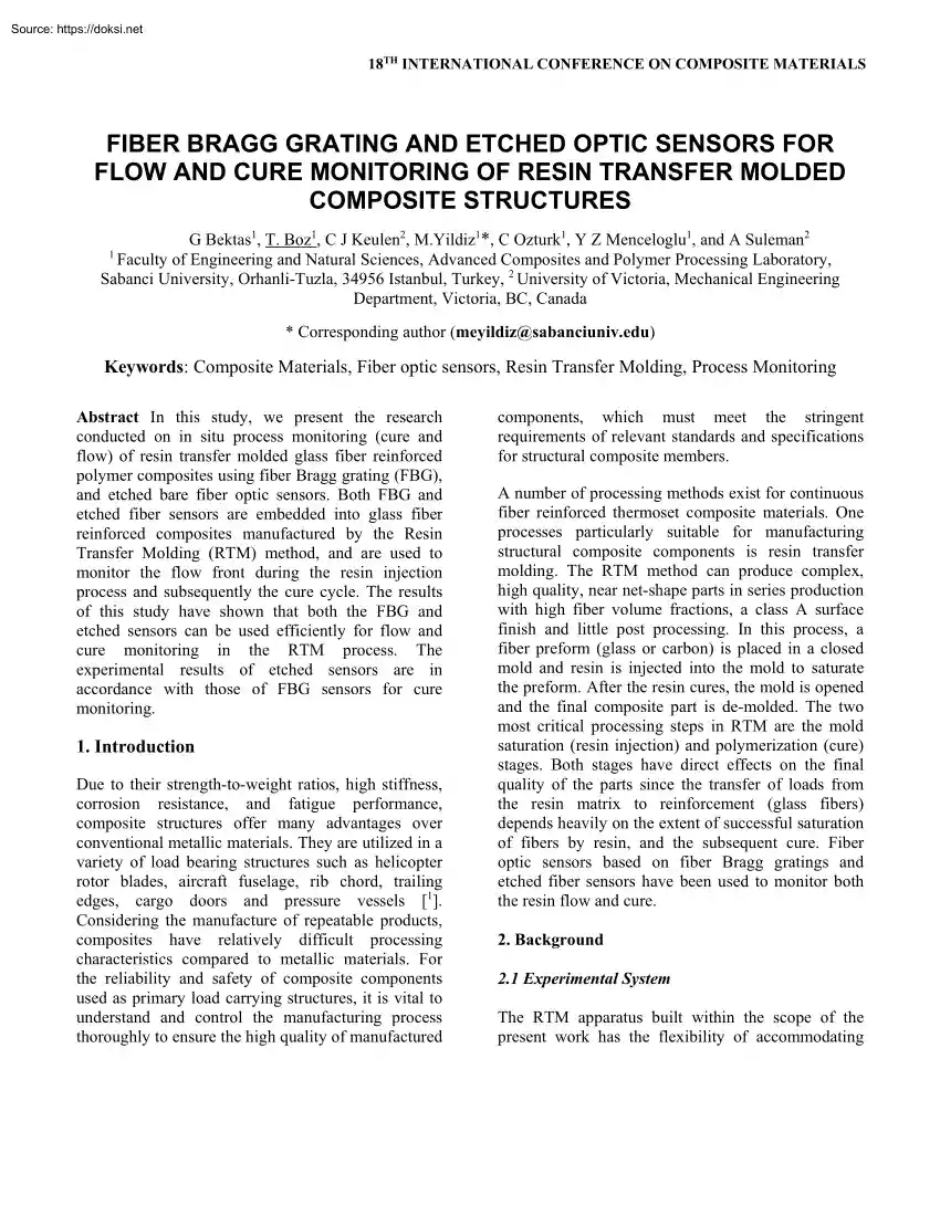
stages. Both stages have direct effects on the final quality of the parts since the transfer of loads from the resin matrix to reinforcement (glass fibers) depends heavily on the extent of successful saturation of fibers by resin, and the subsequent cure. Fiber optic sensors based on fiber Bragg gratings and etched fiber sensors have been used to monitor both the resin flow and cure. 2. Background 2.1 Experimental System The RTM apparatus built within the scope of the present work has the flexibility of accommodating different mold designs and mold thicknesses, with the feature of a glass viewing window to allow for visual monitoring of resin flow through fiber perform during the injection process and thus to ensure that the preform becomes saturated. Fig1 shows a schematic of the RTM process together with the lab scale inhouse built RTM system. (a) (b) Fig.1 Schematic of RTM composite manufacturing process (up), RTM apparatus together with optical equipment (down). Fig. 2 shows
the visualization of resin flow through a fiber glass reinforcement in RTM, the manufactured composite plates with embedded fiber optics sensors (FBG and etched) by using capillary tubes for ingress and egress, and three loop etched sensors for flow and cure monitoring. (c) Fig.2 a-) the visualization of resin flow through a fiber glass reinforcement in RTM, b-) a manufactured composite plate with embedded fiber optic sensors (FBG and etched) by using capillary tubes for ingress and egress, and c-) three loop etched sensors for flow and cure monitoring. 2.2 Fiber optic sensors Two types of fiber optic sensors are used in this study: fiber Bragg gratings (FBG) and etched fiber sensors (EFS). Optical fiber can be seamlessly embedded into composite material with little effect to the host composite. FBG and EFS can be multiplexed on a single fiber allowing multiple sensors to be combined on a single fiber. An FBG sensor is a segment of a single mode optical fiber core with a
periodically modulated refractive index in the direction of fiber length [2,3,4]. The grating segment acts as an optical filter by reflecting a specific wavelength back while transmitting others. The Bragg wavelength satisfies the Bragg condition as in Eq.(1) λB = 2nΛ (1) where λB is the Bragg wavelength, neff is the effective refractive index of the fiber mode and Λ is the pitch of the gratings. The spacing of periodic refractive index modulation is a function of strain and temperature. If an FBG sensor is under a mechanical or thermal load (temperature variation), the spacing between gratings and effective refractive index of the fiber mode will change due to the strain, and thermal expansion, respectively. Since the Bragg wavelength λB is a function of the average refractive index and grating pitch, any change in these variables will cause the Bragg wavelength to shift, meaning that the center wavelength of the reflected spectrum changes. The second type of optic sensors
utilized in this work are etched fiber sensors used to monitor both resin flow front and cure behavior of thermoset polymeric resin [5,6]. This sensor operates in the transmission mode such that a light source sends light into one end of the fiber optic and an optical spectrum analyzer (OSA) measures the transmitted light intensity at the other end. An etched fiber sensor is a bare optical fiber with discrete 3-4 mm etched regions where the cladding thickness is reduced. In this etched area, the external medium essentially becomes a part of the fiber waveguide. If the refractive index of the external medium is smaller than the core of the fiber, there will only be a small perturbation to the fiber mode, and a low loss single mode will still be supported. On the other hand, if the refractive index of the external medium is larger than that of the fiber, the propagating mode will be a leaky mode. This leaky mode can be viewed as a decaying mode due to optical leakage into the higher
refractive index medium. Since the refractive index of the resin is larger than the fiber core, there will be a significant power drop as the resin reaches the etched area, and this property can be employed to monitor resin flow. Since the refractive index of curing resin changes during the curing cycle, we have demonstrated that it is also possible to monitor the curing of RTM manufactured composites with the same etched sensors effectively. 3. Experimental Implementations and Results 3.1 Flow and cure monitoring with FBG sensors Several experiments for cure monitoring of RTM manufactured composite plates by using polyamide coated FBG sensors with an outer diameter of 148 µm were performed. The Bragg wavelength shift of the FBG sensor was monitored by a Micron Optics interrogator of the model sm230. For brevity of the current presentation, results of only two of these experiments are summarized in fig. 3 In these experiments, nine layers of biaxial glass fiber reinforcements are
used. In the experiment for cure monitoring, presented in fig 3a, an FBG sensor with the center wavelength of 1549.76 is positioned on the fifth ply, whereas in the experiment for flow monitoring, three multiplexed FBG sensors with the Bragg wavelengths of 1545-1555-1565 nm are placed on the seventh ply. In the cure monitoring experiment, a room temperature resin is injected into the preheated RTM mold (roughly 30 Celsius to remove the moisture). The first sudden drop in Bragg wavelength in fig. 3a is due to the arrival of room temperature resin on the FBG sensor, which proves the effectiveness of FBG sensors for resin flow front monitoring. Subsequently, the mold is heated to cure temperature of 50 Celsius, which results in an increase of the Bragg wavelength. The fluctuations in fig. 3a correspond to a region where the temperature of the mold was set to the cure temperature. Since the cure process is exothermic in nature, the released heat further increases the center wavelength
of the FBG sensors. As the strength of exothermic process diminishes, the water cooling system under the RTM mold attempts to bring the temperature of the curing plate to the preset cure temperature, thereby resulting in a decrease in the center wavelength of the FBG sensor. However, given the presence of the residual stress built-up (due to various effects such as thermal gradients, shrinkage, and differentials in thermal expansion coefficients) in the curing composite plate, the Bragg wavelength does not return to level which corresponds to the value observed at the preset mold temperature. This case is much more obvious in some other experiments where FBG sensors were positioned farther away from the neutral axis of the 9 layer ply composites. As the polymerization reaction nears completion, the center Bragg wavelength levels off. The region marked with two vertical lines then corresponds to the curing of the epoxy resin system. The closer the sensor is to the neutral axis, the less
strain effect it experiences. Since the strain induced on the structure during the curing process is quite complex in nature, not to preclude the ability of FBG sensors for cure monitoring, FBG sensors should be placed in structures such that it should experience minimum level of residual strain. In other nonreported experiments, we have used different processing conditions; namely, the RTM mold is heated to cure temperature before the injection process. Regardless of experimental conditions, in all experiments, the tendency of wavelength versus processing time is identical, thereby implying the effectiveness of FBG sensors for cure monitoring for RTM composites. Flow monitoring is achieved with three FBG sensors multiplexed on a fiber optic cable. The arrival of resin is sensed due to the contact of resin at room temperature with FBG sensors at mold temperature. The first FBG was positioned near the inlet the second one towards the middle of the mold, and the last one near the outlet
port. Fig 3b indicates the flow front monitoring in RTM system with FBG sensors. To be able to present the changes in the Bragg wavelength of three FBG sensors on the same plot, Bragg wavelength λB values recorded during the resin injection process are subtracted from those values λB,o recorded before the injection. The sudden decreases in the normalized Bragg wavelength values (λB-λB,o) indicate the times when epoxy resin reaches the sensor Fig.3 a-) Experimental data for Bragg wavelength versus processing time for cure (up) and flow (down) monitoring by FBG sensors. 3.2 Flow and cure monitoring with etched fiber optic sensors To create etched fiber sensors the optical fiber is stripped at sensor locations of interest by 3-4 mm with a mechanical optical fiber stripper. The stripped section of the optical fiber is then looped. This is done for two purposes: first, to facilitate the handling process of already fragile optical fiber and the second, to increase the bend loss so that
light intensity drop due to resin arrival is greater and more easily separated from the noise due to the movement of the sensor. These are shown in fig 2c The etching process is conducted on a teflon-jig by forming a small droplet of hydrofluoric acid (38 % HF) on the stripped regions. The teflon-jig has a 3mm diameter spot face that is roughly 5mm deep to contain the HF droplet. The etching process is terminated by washing off the HF with methanol. To investigate the ability and effectiveness of etched sensors for resin flow front and cure monitoring in the operational RTM composite manufacturing system, experiments were conducted with 9 layers of biaxial glass fiber reinforcement. Three etched sensors multiplexed on a length of bare optical fiber were located between the fifth and sixth plies in the RTM mold. The sensors are monitored during the resin injection process to detect the presence of resin and possible dry spots. All etched sensors were prepared with the etching time
of 50-55 minutes, and each of them is fully characterized during their preparation in terms of the light intensity drop. The first etched sensor is placed near the mold inlet, the second one in the middle of the mold, while the last one was positioned towards the outlet port. For etched sensors, the maximum light intensity was continuously monitored. Fig. 4a and 4b present segments of entire the RTM process history recorded by etched optical sensors as shown in fig. 4c Recall that the RTM mold in our experimental set-up has a glass window for visual flow monitoring, which is placed on the bottom surface of the top lid of the mold and fixed therein by means of a room temperature vulcanizing aerospace grade silicon. Due to the flexibility of the silicon, when the mold under vacuum, the glass window is sucked towards the mold cavity exerting more force on the etched sensors at their mold ingress and egress points, hence causing a significant drop in the intensity of the light passing
through the optical fiber. This situation corresponds to the first drop in transmitted light intensity as shown in fig. 4a At that point, to be able to release forces on the sensors, the vacuuming process is terminated and the air inlet to the mold cavity is allowed. As a result, the transmitted light intensity returns back to its initial level. It should be noted that when the mold is closed after the sensors have been positioned within the mold, the intensity of the transmitted light also drops due to the clamping force which over-bends the optical fiber at its ingress and egress points. On launching the resin injection process, the clamping force that causes a drop in transmitted light intensity is counter-balanced by the positive pressure of the injected resin so that the transmitted light intensity tends to increase slightly. Fig.4 a-) The entire history of the RTM process recorded with etched sensors as a light intensity versus processing time, b-) and c-) the close-up view
for a segment of a light intensity drop versus processing time curve. It should be noted that the drop in the light intensity is sum of those due to three multiplexed etched sensor. Once the resin has reached the first etched sensor, the transmitted light intensity drops. As the resin injection proceeds, the clamping force on the optical fiber is further balanced by the pressure of the injected resin, and therefore, the optical fibers are bent less and less at the ingress and egress points. This reflects itself as a slight increase in the transmitted light intensity. When the resin has reached to the second and third sensors, the transmitted light intensity drops again, and then starts increasing again due to the counter-acting pressure effect of the resin. Fig 4a clearly shows that it is possible to record the flow process entirely in terms of resin arrival. To be able to create an entire map of the flow process, a number of discrete etched sensors should be used. Having completed the
infusion process at room temperature, the curing cycle is launched by heating-up the mold to the curing temperature of 50 Celsius. As concluded from fig 4c, with the data acquisition interface developed, we are able to monitor the composite manufacturing process until it is terminated. 4. Conclusion Fiber optic sensors possess many advantages as flow, cure and subsequently structural health monitoring sensors in composite structures. They can be embedded into the structure without changing any mechanical characteristics. Both FBG and etched fiber sensors provide data about the resin flow front ensuring that the mold is fully saturated. With the help of many etched fiber sensors embedded throughout the mold the operator can understand where the resin has reached. In addition to being used for resin flow monitoring in the mold filling process, these sensors can be used for determining the degree of cure, which is required to find out the optimal time for de-molding. In this work the
systematic experimental studies for process monitoring (cure and flow monitoring) for RTM manufactured composite materials is presented. The ability of etched sensors for resin flow front monitoring as well as cure monitoring in an operational RTM process is demonstrated. It has been demonstrated that FBG sensors can also be effectively used for tracking resin flow front. In conclusion, etched fiber sensors can be used as a simple, cost effective alternative to FBG sensors for process monitoring in composite materials manufacturing. The experimental results presented show the potential and the efficiency of the optic sensors for providing real time information about the processing stages of RTM composite manufacturing systems. Acknowledgements The funding provided by The Scientific and Technological Research Council of Turkey (TUBITAK) under the support program of scientific and technological research projects (1001) for the project with the project number of 108M229 is gratefully
acknowledged. References [1] [2] [3] [4] [5] [6] Raymond M. Measures “Structural monitoring with fiber optic technology”, Academic Press, 2001. R. Kashyap “Principles of Optical Fiber Grating Sensors”. Fiber Bragg Gratings (2nd Edition), Pages 441-502, 2010. J. A Guemes, J M Menéndez “Response of Bragg grating fiber-optic sensors when embedded in composite laminates”. Composites Science and Technology 62, pp959-966, 2002 V.M Murukeshan, PY Chan, LS Ong, LK Seah “Cure monitoring of smart composites using fiber Bragg grating based embedded sensors”. Sensors and Actuators A: Physical, Vol. 79, Issue 2, pp153161, 2000 C. Keulen, M Yildiz, A Suleman “Fiber optic sensors for flow and health monitoring of resin transfer molded composite structures”, Proceedings of the Canadian Society for Mechanical Engineering Forum 2010, CSME Forum 2010, Victoria, British Columbia, Canada, 2010. C. Keulen, B Rocha, M Yildiz, ASuleman “ Monitoring the manufacturing, quality and
structural health under operation of resin transfer molded components, 2nd Annual International Symposium on NDT in Aerospace, Hamburg, Germany, 2010
Resin Transfer Molding (RTM) method, and are used to monitor the flow front during the resin injection process and subsequently the cure cycle. The results of this study have shown that both the FBG and etched sensors can be used efficiently for flow and cure monitoring in the RTM process. The experimental results of etched sensors are in accordance with those of FBG sensors for cure monitoring. 1. Introduction Due to their strength-to-weight ratios, high stiffness, corrosion resistance, and fatigue performance, composite structures offer many advantages over conventional metallic materials. They are utilized in a variety of load bearing structures such as helicopter rotor blades, aircraft fuselage, rib chord, trailing edges, cargo doors and pressure vessels [1]. Considering the manufacture of repeatable products, composites have relatively difficult processing characteristics compared to metallic materials. For the reliability and safety of composite components used as primary load
carrying structures, it is vital to understand and control the manufacturing process thoroughly to ensure the high quality of manufactured components, which must meet the stringent requirements of relevant standards and specifications for structural composite members. A number of processing methods exist for continuous fiber reinforced thermoset composite materials. One processes particularly suitable for manufacturing structural composite components is resin transfer molding. The RTM method can produce complex, high quality, near net-shape parts in series production with high fiber volume fractions, a class A surface finish and little post processing. In this process, a fiber preform (glass or carbon) is placed in a closed mold and resin is injected into the mold to saturate the preform. After the resin cures, the mold is opened and the final composite part is de-molded. The two most critical processing steps in RTM are the mold saturation (resin injection) and polymerization (cure)
stages. Both stages have direct effects on the final quality of the parts since the transfer of loads from the resin matrix to reinforcement (glass fibers) depends heavily on the extent of successful saturation of fibers by resin, and the subsequent cure. Fiber optic sensors based on fiber Bragg gratings and etched fiber sensors have been used to monitor both the resin flow and cure. 2. Background 2.1 Experimental System The RTM apparatus built within the scope of the present work has the flexibility of accommodating different mold designs and mold thicknesses, with the feature of a glass viewing window to allow for visual monitoring of resin flow through fiber perform during the injection process and thus to ensure that the preform becomes saturated. Fig1 shows a schematic of the RTM process together with the lab scale inhouse built RTM system. (a) (b) Fig.1 Schematic of RTM composite manufacturing process (up), RTM apparatus together with optical equipment (down). Fig. 2 shows
the visualization of resin flow through a fiber glass reinforcement in RTM, the manufactured composite plates with embedded fiber optics sensors (FBG and etched) by using capillary tubes for ingress and egress, and three loop etched sensors for flow and cure monitoring. (c) Fig.2 a-) the visualization of resin flow through a fiber glass reinforcement in RTM, b-) a manufactured composite plate with embedded fiber optic sensors (FBG and etched) by using capillary tubes for ingress and egress, and c-) three loop etched sensors for flow and cure monitoring. 2.2 Fiber optic sensors Two types of fiber optic sensors are used in this study: fiber Bragg gratings (FBG) and etched fiber sensors (EFS). Optical fiber can be seamlessly embedded into composite material with little effect to the host composite. FBG and EFS can be multiplexed on a single fiber allowing multiple sensors to be combined on a single fiber. An FBG sensor is a segment of a single mode optical fiber core with a
periodically modulated refractive index in the direction of fiber length [2,3,4]. The grating segment acts as an optical filter by reflecting a specific wavelength back while transmitting others. The Bragg wavelength satisfies the Bragg condition as in Eq.(1) λB = 2nΛ (1) where λB is the Bragg wavelength, neff is the effective refractive index of the fiber mode and Λ is the pitch of the gratings. The spacing of periodic refractive index modulation is a function of strain and temperature. If an FBG sensor is under a mechanical or thermal load (temperature variation), the spacing between gratings and effective refractive index of the fiber mode will change due to the strain, and thermal expansion, respectively. Since the Bragg wavelength λB is a function of the average refractive index and grating pitch, any change in these variables will cause the Bragg wavelength to shift, meaning that the center wavelength of the reflected spectrum changes. The second type of optic sensors
utilized in this work are etched fiber sensors used to monitor both resin flow front and cure behavior of thermoset polymeric resin [5,6]. This sensor operates in the transmission mode such that a light source sends light into one end of the fiber optic and an optical spectrum analyzer (OSA) measures the transmitted light intensity at the other end. An etched fiber sensor is a bare optical fiber with discrete 3-4 mm etched regions where the cladding thickness is reduced. In this etched area, the external medium essentially becomes a part of the fiber waveguide. If the refractive index of the external medium is smaller than the core of the fiber, there will only be a small perturbation to the fiber mode, and a low loss single mode will still be supported. On the other hand, if the refractive index of the external medium is larger than that of the fiber, the propagating mode will be a leaky mode. This leaky mode can be viewed as a decaying mode due to optical leakage into the higher
refractive index medium. Since the refractive index of the resin is larger than the fiber core, there will be a significant power drop as the resin reaches the etched area, and this property can be employed to monitor resin flow. Since the refractive index of curing resin changes during the curing cycle, we have demonstrated that it is also possible to monitor the curing of RTM manufactured composites with the same etched sensors effectively. 3. Experimental Implementations and Results 3.1 Flow and cure monitoring with FBG sensors Several experiments for cure monitoring of RTM manufactured composite plates by using polyamide coated FBG sensors with an outer diameter of 148 µm were performed. The Bragg wavelength shift of the FBG sensor was monitored by a Micron Optics interrogator of the model sm230. For brevity of the current presentation, results of only two of these experiments are summarized in fig. 3 In these experiments, nine layers of biaxial glass fiber reinforcements are
used. In the experiment for cure monitoring, presented in fig 3a, an FBG sensor with the center wavelength of 1549.76 is positioned on the fifth ply, whereas in the experiment for flow monitoring, three multiplexed FBG sensors with the Bragg wavelengths of 1545-1555-1565 nm are placed on the seventh ply. In the cure monitoring experiment, a room temperature resin is injected into the preheated RTM mold (roughly 30 Celsius to remove the moisture). The first sudden drop in Bragg wavelength in fig. 3a is due to the arrival of room temperature resin on the FBG sensor, which proves the effectiveness of FBG sensors for resin flow front monitoring. Subsequently, the mold is heated to cure temperature of 50 Celsius, which results in an increase of the Bragg wavelength. The fluctuations in fig. 3a correspond to a region where the temperature of the mold was set to the cure temperature. Since the cure process is exothermic in nature, the released heat further increases the center wavelength
of the FBG sensors. As the strength of exothermic process diminishes, the water cooling system under the RTM mold attempts to bring the temperature of the curing plate to the preset cure temperature, thereby resulting in a decrease in the center wavelength of the FBG sensor. However, given the presence of the residual stress built-up (due to various effects such as thermal gradients, shrinkage, and differentials in thermal expansion coefficients) in the curing composite plate, the Bragg wavelength does not return to level which corresponds to the value observed at the preset mold temperature. This case is much more obvious in some other experiments where FBG sensors were positioned farther away from the neutral axis of the 9 layer ply composites. As the polymerization reaction nears completion, the center Bragg wavelength levels off. The region marked with two vertical lines then corresponds to the curing of the epoxy resin system. The closer the sensor is to the neutral axis, the less
strain effect it experiences. Since the strain induced on the structure during the curing process is quite complex in nature, not to preclude the ability of FBG sensors for cure monitoring, FBG sensors should be placed in structures such that it should experience minimum level of residual strain. In other nonreported experiments, we have used different processing conditions; namely, the RTM mold is heated to cure temperature before the injection process. Regardless of experimental conditions, in all experiments, the tendency of wavelength versus processing time is identical, thereby implying the effectiveness of FBG sensors for cure monitoring for RTM composites. Flow monitoring is achieved with three FBG sensors multiplexed on a fiber optic cable. The arrival of resin is sensed due to the contact of resin at room temperature with FBG sensors at mold temperature. The first FBG was positioned near the inlet the second one towards the middle of the mold, and the last one near the outlet
port. Fig 3b indicates the flow front monitoring in RTM system with FBG sensors. To be able to present the changes in the Bragg wavelength of three FBG sensors on the same plot, Bragg wavelength λB values recorded during the resin injection process are subtracted from those values λB,o recorded before the injection. The sudden decreases in the normalized Bragg wavelength values (λB-λB,o) indicate the times when epoxy resin reaches the sensor Fig.3 a-) Experimental data for Bragg wavelength versus processing time for cure (up) and flow (down) monitoring by FBG sensors. 3.2 Flow and cure monitoring with etched fiber optic sensors To create etched fiber sensors the optical fiber is stripped at sensor locations of interest by 3-4 mm with a mechanical optical fiber stripper. The stripped section of the optical fiber is then looped. This is done for two purposes: first, to facilitate the handling process of already fragile optical fiber and the second, to increase the bend loss so that
light intensity drop due to resin arrival is greater and more easily separated from the noise due to the movement of the sensor. These are shown in fig 2c The etching process is conducted on a teflon-jig by forming a small droplet of hydrofluoric acid (38 % HF) on the stripped regions. The teflon-jig has a 3mm diameter spot face that is roughly 5mm deep to contain the HF droplet. The etching process is terminated by washing off the HF with methanol. To investigate the ability and effectiveness of etched sensors for resin flow front and cure monitoring in the operational RTM composite manufacturing system, experiments were conducted with 9 layers of biaxial glass fiber reinforcement. Three etched sensors multiplexed on a length of bare optical fiber were located between the fifth and sixth plies in the RTM mold. The sensors are monitored during the resin injection process to detect the presence of resin and possible dry spots. All etched sensors were prepared with the etching time
of 50-55 minutes, and each of them is fully characterized during their preparation in terms of the light intensity drop. The first etched sensor is placed near the mold inlet, the second one in the middle of the mold, while the last one was positioned towards the outlet port. For etched sensors, the maximum light intensity was continuously monitored. Fig. 4a and 4b present segments of entire the RTM process history recorded by etched optical sensors as shown in fig. 4c Recall that the RTM mold in our experimental set-up has a glass window for visual flow monitoring, which is placed on the bottom surface of the top lid of the mold and fixed therein by means of a room temperature vulcanizing aerospace grade silicon. Due to the flexibility of the silicon, when the mold under vacuum, the glass window is sucked towards the mold cavity exerting more force on the etched sensors at their mold ingress and egress points, hence causing a significant drop in the intensity of the light passing
through the optical fiber. This situation corresponds to the first drop in transmitted light intensity as shown in fig. 4a At that point, to be able to release forces on the sensors, the vacuuming process is terminated and the air inlet to the mold cavity is allowed. As a result, the transmitted light intensity returns back to its initial level. It should be noted that when the mold is closed after the sensors have been positioned within the mold, the intensity of the transmitted light also drops due to the clamping force which over-bends the optical fiber at its ingress and egress points. On launching the resin injection process, the clamping force that causes a drop in transmitted light intensity is counter-balanced by the positive pressure of the injected resin so that the transmitted light intensity tends to increase slightly. Fig.4 a-) The entire history of the RTM process recorded with etched sensors as a light intensity versus processing time, b-) and c-) the close-up view
for a segment of a light intensity drop versus processing time curve. It should be noted that the drop in the light intensity is sum of those due to three multiplexed etched sensor. Once the resin has reached the first etched sensor, the transmitted light intensity drops. As the resin injection proceeds, the clamping force on the optical fiber is further balanced by the pressure of the injected resin, and therefore, the optical fibers are bent less and less at the ingress and egress points. This reflects itself as a slight increase in the transmitted light intensity. When the resin has reached to the second and third sensors, the transmitted light intensity drops again, and then starts increasing again due to the counter-acting pressure effect of the resin. Fig 4a clearly shows that it is possible to record the flow process entirely in terms of resin arrival. To be able to create an entire map of the flow process, a number of discrete etched sensors should be used. Having completed the
infusion process at room temperature, the curing cycle is launched by heating-up the mold to the curing temperature of 50 Celsius. As concluded from fig 4c, with the data acquisition interface developed, we are able to monitor the composite manufacturing process until it is terminated. 4. Conclusion Fiber optic sensors possess many advantages as flow, cure and subsequently structural health monitoring sensors in composite structures. They can be embedded into the structure without changing any mechanical characteristics. Both FBG and etched fiber sensors provide data about the resin flow front ensuring that the mold is fully saturated. With the help of many etched fiber sensors embedded throughout the mold the operator can understand where the resin has reached. In addition to being used for resin flow monitoring in the mold filling process, these sensors can be used for determining the degree of cure, which is required to find out the optimal time for de-molding. In this work the
systematic experimental studies for process monitoring (cure and flow monitoring) for RTM manufactured composite materials is presented. The ability of etched sensors for resin flow front monitoring as well as cure monitoring in an operational RTM process is demonstrated. It has been demonstrated that FBG sensors can also be effectively used for tracking resin flow front. In conclusion, etched fiber sensors can be used as a simple, cost effective alternative to FBG sensors for process monitoring in composite materials manufacturing. The experimental results presented show the potential and the efficiency of the optic sensors for providing real time information about the processing stages of RTM composite manufacturing systems. Acknowledgements The funding provided by The Scientific and Technological Research Council of Turkey (TUBITAK) under the support program of scientific and technological research projects (1001) for the project with the project number of 108M229 is gratefully
acknowledged. References [1] [2] [3] [4] [5] [6] Raymond M. Measures “Structural monitoring with fiber optic technology”, Academic Press, 2001. R. Kashyap “Principles of Optical Fiber Grating Sensors”. Fiber Bragg Gratings (2nd Edition), Pages 441-502, 2010. J. A Guemes, J M Menéndez “Response of Bragg grating fiber-optic sensors when embedded in composite laminates”. Composites Science and Technology 62, pp959-966, 2002 V.M Murukeshan, PY Chan, LS Ong, LK Seah “Cure monitoring of smart composites using fiber Bragg grating based embedded sensors”. Sensors and Actuators A: Physical, Vol. 79, Issue 2, pp153161, 2000 C. Keulen, M Yildiz, A Suleman “Fiber optic sensors for flow and health monitoring of resin transfer molded composite structures”, Proceedings of the Canadian Society for Mechanical Engineering Forum 2010, CSME Forum 2010, Victoria, British Columbia, Canada, 2010. C. Keulen, B Rocha, M Yildiz, ASuleman “ Monitoring the manufacturing, quality and
structural health under operation of resin transfer molded components, 2nd Annual International Symposium on NDT in Aerospace, Hamburg, Germany, 2010
 When reading, most of us just let a story wash over us, getting lost in the world of the book rather than paying attention to the individual elements of the plot or writing. However, in English class, our teachers ask us to look at the mechanics of the writing.