Please log in to read this in our online viewer!
Please log in to read this in our online viewer!
No comments yet. You can be the first!
What did others read after this?
Content extract
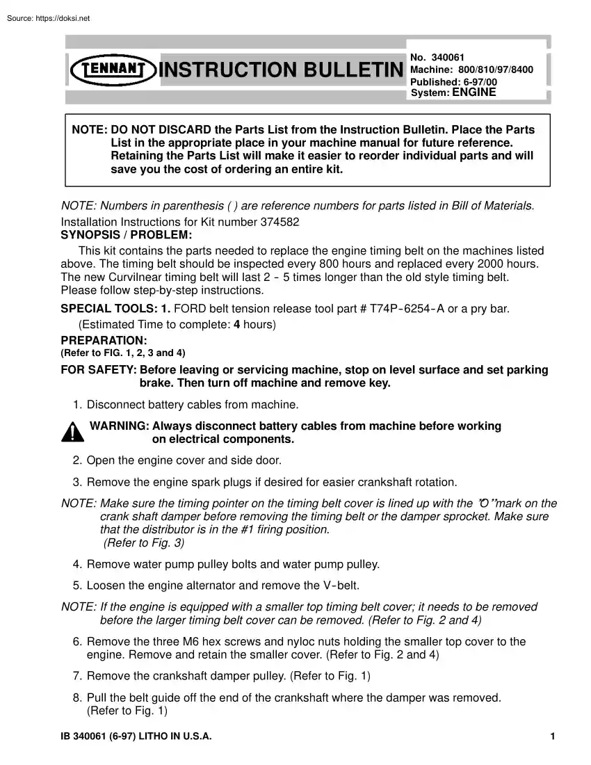
INSTRUCTION BULLETIN No. 340061 Machine: 800/810/97/8400 Published: 6-97/00 System: ENGINE NOTE: DO NOT DISCARD the Parts List from the Instruction Bulletin. Place the Parts List in the appropriate place in your machine manual for future reference. Retaining the Parts List will make it easier to reorder individual parts and will save you the cost of ordering an entire kit. NOTE: Numbers in parenthesis ( ) are reference numbers for parts listed in Bill of Materials. Installation Instructions for Kit number 374582 SYNOPSIS / PROBLEM: This kit contains the parts needed to replace the engine timing belt on the machines listed above. The timing belt should be inspected every 800 hours and replaced every 2000 hours The new Curvilnear timing belt will last 2 -- 5 times longer than the old style timing belt. Please follow step-by-step instructions. SPECIAL TOOLS: 1. FORD belt tension release tool part # T74P--6254--A or a pry bar (Estimated Time to complete: 4 hours) PREPARATION: (Refer to
FIG. 1, 2, 3 and 4) FOR SAFETY: Before leaving or servicing machine, stop on level surface and set parking brake. Then turn off machine and remove key 1. Disconnect battery cables from machine WARNING: Always disconnect battery cables from machine before working on electrical components. 2. Open the engine cover and side door 3. Remove the engine spark plugs if desired for easier crankshaft rotation NOTE: Make sure the timing pointer on the timing belt cover is lined up with the ”O”mark on the crank shaft damper before removing the timing belt or the damper sprocket. Make sure that the distributor is in the #1 firing position. (Refer to Fig. 3) 4. Remove water pump pulley bolts and water pump pulley 5. Loosen the engine alternator and remove the V--belt NOTE: If the engine is equipped with a smaller top timing belt cover; it needs to be removed before the larger timing belt cover can be removed. (Refer to Fig 2 and 4) 6. Remove the three M6 hex screws and nyloc nuts holding the
smaller top cover to the engine. Remove and retain the smaller cover (Refer to Fig 2 and 4) 7. Remove the crankshaft damper pulley (Refer to Fig 1) 8. Pull the belt guide off the end of the crankshaft where the damper was removed (Refer to Fig. 1) IB 340061 (6-97) LITHO IN U.SA 1 9. Remove the five hex screws holding the large timing belt cover to the engine Remove and retain the large cover. (Refer to Fig 2) Flat washer Belt guide (re-- use) Hex screw Crankshaft sprocket Crankshaft damper FIG. 1 - Crankshaft Damper NOTE: The tension on the timing belt needs to be released before the belt can be removed. 10. Loosen the belt tensioner adjustment screw and release the tension on the timing belt Once the tension is released, re--tighten the tensioner adjustment screw. New Camshaft sprocket (has belt guide and timing mark) Access plug Engine timing belt cover Timing belt New Auxiliary sprocket (has NO belt guide or timing mark) Top timing belt cover New Crankshaft sprocket 18
New timing mark (punch mark) Cover backing plate FIG. 2 - Timing Belt Covers NOTE: A special tension release tool is available from FORD. The part number is T74P--6254--A. A small pry bar may be used in place of this tool 11. Remove the old timing belt, camshaft sprocket, auxiliary sprocket, and crankshaft sprocket Clean any dirt that has accumulated in the timing belt area. (Refer to Fig 2 & 3) 2 IB 340061 (6-97) LITHO IN U.SA INSTALLATION: (Refer to FIG. 1, 2, 3 and 4) 1. Install the new crankshaft sprocket with belt guide as shown, camshaft sprocket, and auxiliary timing sprocket with chamfered edges toward engine. 2. Before installing a new timing belt, make sure the camshaft sprocket timing mark lines up with the timing pointer on the engine. (Refer to Fig 3) 3. Remove the distributor cap and set the distributor rotor to number 1 firing position by turning the auxiliary shaft sprocket. Reinstall the distributor cap (Refer to Fig 2 and 4) 4. Install the new timing
belt (1) over the crankshaft sprocket and then counterclockwise over the the auxiliary and camshaft sprockets. Align the belt fore and aft on each sprocket (Refer to Fig. 3) New camshaft sprocket This timing pointer is located on the inner cover. Line up the timing dot on the new camshaft sprocket with the center point. (”TC”) FIG. 3 - Timing Marks 5. Loosen the tensioner adjustment bolt to allow the tensioner to move against the belt 6. Rotate the crankshaft two complete turns in normal rotation to remove the slack from the belt. (Refer to Fig 3) 7. Re--check the alignment of the timing marks (Refer to Fig 3) 8. Reinstall the spark plugs 9. Reinstall the belt guide and damper to the crankshaft (Refer to Fig 1) 10. Reinstall the timing belt cover and the five hex screws (Refer to Fig 2) IB 340061 (6-97) LITHO IN U.SA 3 11. Reinstall the small, top cover on the timing belt cover Hand tighten the three M6 hex screws and nyloc nuts. (Refer to Fig 2 and 4) 12. Reinstall the
water pump pulley Timing belt cover Firing position #1 FIG. 4 - Engine Assembly 13. Reinstall the alternator V--belt, pull the alternator to tension the belt, tighten the alternator mount bolts. 14. Reconnect the battery cables Start the engine and check the timing With the governor unhooked, the vacuum advance hose removed and plugged, and the engine running at 800rpm’s or less, the timing should be 10 degrees BTDC. Adjust if necessary (Refer to Fig. 3) NOTE: The 2.3 liter engine is very sensitive to proper ignition timing Set as close as possible Ref. BILL OF MATERIALS FOR TIMING BELT KIT 374582 TENNANT Part No. Description Qty. 1 2 3 4 374576 374580 374581 84924 1 1 1 1 Timing belt Sprocket, camshaft Sprocket, auxiliary Sprocket, crankshaft TENNANT COMPANY P. O Box 1452 Minneapolis, MN 55440-1452 4 IB 340061 (6-97) LITHO IN U.SA
