Comments
No comments yet. You can be the first!
Most popular documents in this category


Content extract
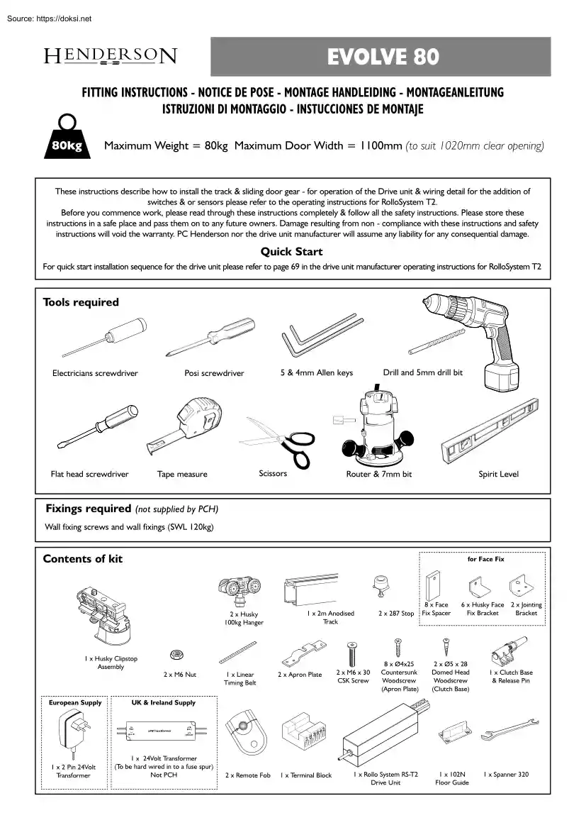
EVOLVE 80 FITTING INSTRUCTIONS - NOTICE DE POSE - MONTAGE HANDLEIDING - MONTAGEANLEITUNG ISTRUZIONI DI MONTAGGIO - INSTUCCIONES DE MONTAJE 80kg Maximum Weight = 80kg Maximum Door Width = 1100mm (to suit 1020mm clear opening) These instructions describe how to install the track & sliding door gear - for operation of the Drive unit & wiring detail for the addition of switches & or sensors please refer to the operating instructions for RolloSystem T2. Before you commence work, please read through these instructions completely & follow all the safety instructions. Please store these instructions in a safe place and pass them on to any future owners. Damage resulting from non - compliance with these instructions and safety instructions will void the warranty. PC Henderson nor the drive unit manufacturer will assume any liability for any consequential damage Quick Start For quick start installation sequence for the drive unit please refer to page 69 in the drive unit
manufacturer operating instructions for RolloSystem T2 Tools required Electricians screwdriver Scissors Tape measure Flat head screwdriver Drill and 5mm drill bit 5 & 4mm Allen keys Posi screwdriver Router & 7mm bit Spirit Level Fixings required (not supplied by PCH) Wall fixing screws and wall fixings (SWL 120kg) Contents of kit for Face Fix 2 x Husky 100kg Hanger 1 x 2m Anodised Track 1 x Husky Clipstop Assembly 2 x M6 Nut European Supply UK & Ireland Supply 1 x 2 Pin 24Volt Transformer 1 x 24Volt Transformer (To be hard wired in to a fuse spur) Not PCH 1 x Linear Timing Belt 2 x Apron Plate 2 x Remote Fob 1 x Terminal Block 2 x 287 Stop 8 x Face Fix Spacer 6 x Husky Face 2 x Jointing Fix Bracket Bracket 8 x Ø4x25 Countersunk Woodscrew (Apron Plate) 2 x Ø5 x 28 Domed Head Woodscrew (Clutch Base) 1 x Rollo System RS-T2 Drive Unit 1 x 10²N Floor Guide 2 x M6 x 30 CSK Screw 1 x Clutch Base & Release Pin 1 x Spanner 320 Wiring
diagram - European Drive Unit to 2 Pin Plug Connection Wiring GREY 2 YELLOW 4 PINK 6 WHITE 3 GREEN 5 BROWN 1 Drive Unit 1 5 3 6 4 2 2 Pin European Socket MARKED 1 UNMARKED 5 2 Pin Plug European 24 Volt Transformer Terminal Block Wiring diagram - UK and Ireland Drive Unit to Transformer Connection Wiring GREY 2 YELLOW 4 PINK 6 WHITE 3 GREEN 5 BROWN 1 Drive Unit 1 5 3 6 4 2 Fused Spur (Not PCH) RED 1 BLACK 5 24 Volt Transformer Terminal Block 1 Secure drive unit to track 2 Rebate door for 102N (if guide required) M6 x 30 Track Drive Unit M6 Nuts 14 7 3 Attach hanger plates and clutch base to top of door Do NOT hang doors or affix track at this stage Ø5 x 28 Dome Head Woodscrews 80 100 Offset calculation Ø4 x 25 Countersunk Woodscrews 280 Offset Clutch Base Position 1/2 B 20 Apron Plate Position 4 Insert track components Tension Wheel / Clip Stop Assembly Track Stop Clip Stop Body Hanger M6 x 40 (used to position within the track) Hanger Track Stop
Tension Wheel Assembly 5 Remove covers to allow linear timing belt to be attached Drive Wheel Cover Tension Wheel Cover 6 Cut linear timing belt to length (no overlap required) Torsion wheel to be positioned at the end of the track 7 Fit clutch pin to connect both ends of the linear timing belt Clutch pin Cone Cone Ends of the belt meet centrally in the pin body Click 8 Tension linear timing belt Tension Guide Push tension wheel assembly so the belt is torte and secure assembly in position by tightening the M6 bolt M6 bolt 9 Refit drive wheel and tension wheel covers Drive Wheel Cover Tension Wheel Cover Ensure cone locates into the recess of the clip stop body to prevent rotation 10 Secure track A - Fit suitable wall anchors (Not PCH) Suitably rated wall plugs recommended (NOT PCH) B - Attach brackets B.1 - Face Fix Option 281A 281AX C - Affix track to wall B.2 - Soffit Fix Option D - Check level prior to firm fix = = = = = = = Check level 11
Hang door and adjust height 32 + 0-3mm Using supplied spanner secure door to track 12 Fit door guide (if guide required) Spirit Level 13 Set stops in track to suit required travel Secure end stops in track 14 Door height and overlap calculation 15 Engage the clutch pin into the base then follow drive set up instructions 33 8 35 67.5 + 0-3mm X= minimum overlap = 13mm 3-6mm clear of bottom of drive unit B DH = (OH+X -5mm) DH OH For English language operation instructions & external motion /sensor wiring please refer to the drive unit manufacturers manual from page 49. 7 14 5mm minimum ground clearance 16 2.5 25.5 P C Henderson Limited, Durham Road, Bowburn, County Durham DH6 5NG, UK. Web: wwwpchendersoncom UK Customer Services Department: Tel: +44 (0)191 377 7345 Fax: +44 (0)191 377 3116 Email: sales@pchenderson.com Export Department: Tel: +44 (0)191 377 7346 Fax: +44 (0)191 377 0755. Email: international@pchendersoncom For all technical queries email our
Technical Department: technical@pchenderson.com Part No: 668373 December 2012 - Issue 4 Please note The original languages of these instructions are English. The airborne noise of the system under normal operating conditions does not exceed 70dB (A). Manufacturers Declaration of Incorporation Manufacturer: PC Henderson Ltd Durham Road Bowburn Durham DH6 5NG Telephone: Fax: 0191 377 7345 0191 377 3116 General safety precautions This installation manual is intended for professionally competent personnel only. Installation, electrical connections and adjustments must be performed in accordance with Good Working Methods and in compliance with applicable regulations. Before installing the product, carefully read the instructions. Bad installation could be hazardous. The packaging materials (plastic, polystyrene, etc.) should not be discarded in the environment or left within reach of children, as these are a potential source of hazard. Before installing the product, make sure it
is in perfect condition. Do not install the product in an explosive environment and atmosphere: gas or inflammable fumes are a serious risk hazard. Before installing the system, ensure all structural changes relating to safety clearances and protection or segregation of all areas where there is risk of being crushed, cut or dragged, and danger areas in general. Make sure the existing structure is up to standard in terms of strength and stability. Each installation must clearly show the identification details of the motorized door or gate. Apply hazard area notices required by applicable regulations. The electricity supply must be isolated at its source before attempting installation or maintenance. Hereby declares that the electromechanical automatic door operating system Evolve 80 Evolve 80 SIM Kit Evolve 60 Pocket Door Kit Are intended to be incorporated into machinery or to be assembled with other machinery to constitute machinery covered by directive 2006/42/EC It is in conformity
with the provisions of the following directives: Electromagnetic Directive 2004/108/EC The technical file is maintained at: PC Henderson Ltd Durham Road Bowburn Durham. DH6 5NG Disclaimer PC Henderson nor the drive unit manufacturer take responsibility for failure to use Good Working Methods in building the frames to be motorized or for any deformation occurring during use. PC Henderson & the drive unit manufacturer declines all responsibility in the event of component parts being fitted that are not compatible with the safe and correct operation. For repairs or replacements of products only original spare parts must be used. The authorised representative located within the community is: Installer responsibility The above named undertakes to transmit in response to a reasoned request by national authorities, relevant information on the partly completed machinery. The installer should provide technical documentation once the installation is complete, this should include - EC
declaration of conformity with the machinery directive - Installation manual - Maintenance / Trouble shooting guide (supplied in the drive unit manufacturer operation manual) The installer is also responsible for affixing final CE mark upon the installation. Fergus Pickard Product Development Director PC Henderson Ltd Durham Road Bowburn Durham. DH6 5NG Fergus Pickard, Product Development Director Bowburn, Durham 25/07/12 Operating Instructions for Evolve Automation Sliding Door system Release operation In the event of malfunction or if there is no mains power supply, move the door manually. General Safety Precautions The following precautions are an integral & essential part of the product and must be supplied to the end user. Read them carefully as they contain important indications for the safe installation, use and maintenance. These instructions must be kept and forwarded to all possible future users of the system. This product must be used only for that which it has
been expressly designed; any other use is to be considered improper and therefore dangerous. The manufacturer cannot be held responsible for possible damage caused by improper, erroneous or unreasonable use. Avoid operating in the proximity of moving mechanical parts. Do not enter the field of danger of the motorised door while in motion. Do not obstruct the motion of the motorised door as this may cause a situation of danger. Do not lean against or hang on to the barrier when it is moving. Do not allow children to play or stay within the field of action of the motorised door. Keep remote control or any other control devices out of reach of children, in order to avoid possible involuntary activation of the motorised door. In the case of breakdown or malfunction of the product, disconnect from the mains, do not attempt to repair or intervene directly & contact only qualified personnel. Failure to comply with the above may create a situation of danger. All cleaning, maintenance or
repair work must be carried out by qualified personnel. In order to guarantee that the system works efficiently and correctly it is indispensable to comply with the manufacturers indications thus having periodic maintenance of the motorised door carried out by qualified personnel. In particular regular checks are recommended in order to verify that the safety devices are operating correctly. All installation, maintained and repair work must be documented and made available to the end user. Installer training available upon request, please note this attracts a fee. INSTALLER EC Declaration of Conformity - Machine Directive 2006/42/CE Schedule II Part 2 Manufacturer: PC Henderson Ltd Address: Durham Road, Bowburn, Durham, DH6 5NG Name & Address of authorised installer: Hereby Declare: Henderson Evolve 80 Evolve 80 SIM Kit Evolve 60 (Pocket door) Installed at (Installation address): Conforms to Directive: 2006/42/CE – Machine Directive State that it fulfils the applicable
portions of the following standard Date & location of Signature: Signature of the person legally responsible: This completed document forms part of the European conformity (CE marking) – to be completed by installer & forwarded to end user. Must be kept for ten years from installation date. Markings Each installation must clearly show the identification details of the motorized door or gate. The installer should apply hazard area notices required by applicable regulations, such as that shown below. The installer must affix & complete the data tag supplied to the final installation in a suitable prominent position. P C Henderson Limited www.pchendersoncom The installer must affix warning signs to the installation on both sides of the door, similar to those shown. INSTALLER Durham Road, Bowburn, County Durham, DH6 5NG, UK Tel:+44(0)191 377 7345 e-mail: sales@pchenderson.com DATE Installer to complete with contact details; Address & telephone number; to be
completed with legible and permanent black ink. Toothed belt wheel Toothed belt wheel cover Hanger Provides drive to machine Moving part protective cover Door is suspended from Hanger Provides movement to doors within system Stripping of teeth - discolouration - Slipping Cracking - discolouration Black deposits within track / on top of door Repeated error messages - failure of machine Fraying/Shearing - elongation - discolouration Cracking - excessive wear - slipping Cracking - discolouration - slipping Supports belt movement within machine Moving part protective cover Provides movement to doors within system Degradation of component indicators Description of function From new - Six months - once a year thereafter From new - Six months - once a year thereafter From new - Six months - once a year thereafter From new - Six months - once a year thereafter From new - Six months - once a year thereafter Maintenance interval From new - Six months - once a year thereafter From
new - Six months - once a year thereafter From new - Six months - once a year thereafter * = or sooner dependent upon operating conditions. # = Replacement only recommended when apparent excessive wear affects the performance of the installation 668320 (c/w 2 pin Euro plug) 668354(c/w 24v transformer) By Special request only By Special request only 665507 Drive unit Linear timing belt Part Number 668349 668324 668323 668350 (4.5mtr); 668351(40 mtr); 668352 (9.0mtr) Part Description Tension wheel assembly Tension wheel sub assembly Wheel cover Critical Parts Maintenance Schedule Turn off the power - Clean the moving parts - Check the belt tension - Clean the sensors/ remote fob (where applicable) - Check the stability of the automatic system and make sure that all screws are correctly tightened. - Check the alignment of the door and the stop positions Turn on the power - Check the stability of the door and that the movement is regular and without friction. - Check that all
command functions are operating correctly. - Check that the doors developed powers are in accordance with the present standards. Maintenance schedule # # # # Every 2 years of service* Planned replacement schedule # Every 10 years of service* # Proof Book This proof book contains technical references and records of installation, maintenance, repair and alterations carried out and must be made available for any inspection by authorised bodies. This book should be completed by the installer and forwarded to the end user. Specifications of the motorised door and installation Customer: Order Number: Model & description: Dimensions and Weight: Location: List of components installed Motor /Drive unit Switch: Remote Fob: Motion Sensor: Sign off check sheet: Declaration of conformity filled out Henderson & the drive unit manufacturer fitting instructions Proof book filled out All documents left with end user CE label completed & installed in suitable location
Signature of receipt Warning signs installed in suitable location Warning of residual risks and of foreseeable improper use Inform the end user of risk points regarding existing risks and foreseeable improper use. Proof Book Description of the work Installation Details: Start up Adjustments Maintenance Repairs Alterations Date: Technicians Signature: Customers Signature: Description of the work Installation Details: Start up Adjustments Maintenance Repairs Alterations Date: Technicians Signature: Customers Signature: Description of the work Installation Details: Start up Adjustments Maintenance Repairs Alterations Date: Technicians Signature: Customers Signature: Description of the work Installation Details: Start up Adjustments Maintenance Repairs Alterations Date: Technicians Signature: Customers Signature:
 Just like you draw up a plan when you’re going to war, building a house, or even going on vacation, you need to draw up a plan for your business. This tutorial will help you to clearly see where you are and make it possible to understand where you’re going.