Comments
No comments yet. You can be the first!
Most popular documents in this category


Content extract
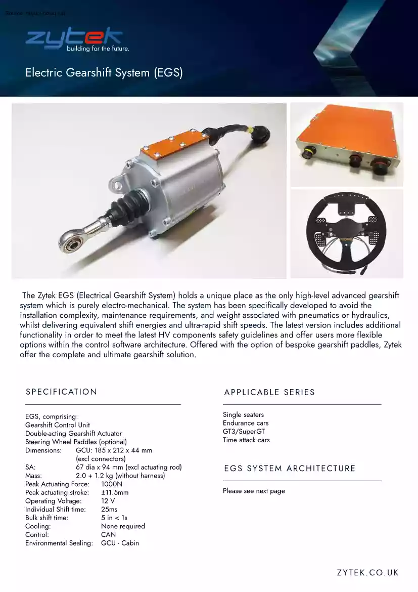
Electric Gearshift System (EGS) The Zytek EGS (Electrical Gearshift System) holds a unique place as the only high-level advanced gearshift system which is purely electro-mechanical. The system has been specifically developed to avoid the installation complexity, maintenance requirements, and weight associated with pneumatics or hydraulics, whilst delivering equivalent shift energies and ultra-rapid shift speeds. The latest version includes additional functionality in order to meet the latest HV components safety guidelines and offer users more flexible options within the control software architecture. Offered with the option of bespoke gearshift paddles, Zytek offer the complete and ultimate gearshift solution. S P E C I F I C AT I O N APPLICABLE SERIES EGS, comprising: Gearshift Control Unit Double-acting Gearshift Actuator Steering Wheel Paddles (optional) Dimensions: GCU: 185 x 212 x 44 mm (excl connectors) SA: 67 dia x 94 mm (excl actuating rod) Mass: 2.0 + 12 kg
(without harness) Peak Actuating Force: 1000N Peak actuating stroke: ±11.5mm Operating Voltage: 12 V Individual Shift time: 25ms Bulk shift time: 5 in < 1s Cooling: None required Control: CAN Environmental Sealing: GCU - Cabin Single seaters Endurance cars GT3/SuperGT Time attack cars E G S S Y S T E M A R C H I T E CT U R E Please see next page Z Y T E K . C O U K Electric Gearshift System (EGS) E G S S Y S T E M A R C H I T E CT U R E C O N N E CTO R I N F O R M AT I O N Power Connector: AS6 16-08SN Pin Signal A +12V Supply (Master switch) B +12V Supply (Master switch) C Ground D Ground E Clutch Actuator + F Clutch Actuator - E G S A C T U ATO R F O R C E D I S P L AC E M E N T Signal Connector: AS6 14-35SN Pin Signal 1 Diagnostic CAN Low 2 Vehicle CAN High 3 Vehicle CAN Low 4 Logging CAN High 5 Logging CAN Low 6 GCU HV Enable 7 GCU Enable 8 Spare Signal / Screen Ground 9 HW Shift Control Dig in 1 10 HW Shift Control Dig in 2 11 Spare Sensor Supply 12 Clutch
Position Sensor Signal A 13 Clutch Position Sensor Supply 14 Clutch Pressure Sensor Supply 15 Gear Position Sensor Supply 16 ECS CAN High 17 ECS CAN Low 18 Diagnostic CAN High 19 Vehicle CAN Screen 20 Logging CAN Screen 21 Spare Signal / Screen Ground Spare Signal / Screen Ground 22 Spare Ground 23 HW Shift Control Dig in 3 24 HW Shift Control Dig in 4 25 Clutch Position Sensor Signal B 26 Clutch Pressure Sensor Signal 27 Gear Position Sensor Signal A 28 ECS CAN Screen 29 Diagnostic CAN Screen 30 Spare Analogue Input 2 31 Spare Analogue Input 3 32 Clutch Position Sensor Ground 33 Clutch Pressure Sensor Ground 34 Gear Position Sensor Signal B 35 Spare Analogue Input 1 36 Gear Position Sensor Ground 37 Z Y T E K . C O U K
 When reading, most of us just let a story wash over us, getting lost in the world of the book rather than paying attention to the individual elements of the plot or writing. However, in English class, our teachers ask us to look at the mechanics of the writing.