Please log in to read this in our online viewer!
Please log in to read this in our online viewer!
No comments yet. You can be the first!
What did others read after this?


Content extract
CH-53E M3M Ramp Mounted Weapon System Anthony C. Archer anthony.carcher@navymil Major USMC Christopher J. Barrett christopher.barrett@navymil Flight Test Engineer Air Test and Evaluation Squadron TWO ONE 22755 Saufley Road Patuxent River, Maryland 20670 AbstractThe U.S Marine Corps (USMC) CH-53E Super Stallion has always had a .50-caliber crew-served machine gun mounted on each side of the aircraft to provide suppressive, defensive fire. However, these door guns only provide partial protection in the forward hemisphere, leaving the rear hemisphere of the aircraft completely unprotected. This defensive shortcoming is especially dangerous during long-range missions where the CH-53E may go unescorted by shorter-range attack helicopters. Air Test and Evaluation Squadron Two One (HX-21) was tasked to evaluate a Ramp Mounted Weapon System (RMWS), which would provide a rear hemisphere, defensive fire capability. The RMWS tested was an M3M .50-caliber machine gun and mount assembly developed
by Fabrique National (FN) Herstal. Ground testing was conducted to evaluate compatibility and functionality of the system. Flight testing was conducted to evaluate compatibility, functionality, and effectiveness of the RMWS. Safe separation of ammunition links and casings was evaluated through a flight envelope expansion in airspeed, pitch, pitch rate, roll, roll rate, and rate of descent. Flight tests also involved structural data gathering and an indepth ramp-to-deck clearance evaluation to optimize pilot technique during takeoff and landing with the system employed. The primary deficiencies discovered during testing were not a function of the gun system itself but a result of the aircraft and crew station when employing the gun system.12 1. INTRODUCTION The U.S Air Force (USAF) has employed a RMWS on its MH-53J and MH-53M PAVELOW helicopters (converted USMC CH-53As) since their inception into the Special Operations Wing. This system provides the MH-53J and MH-53M with rear
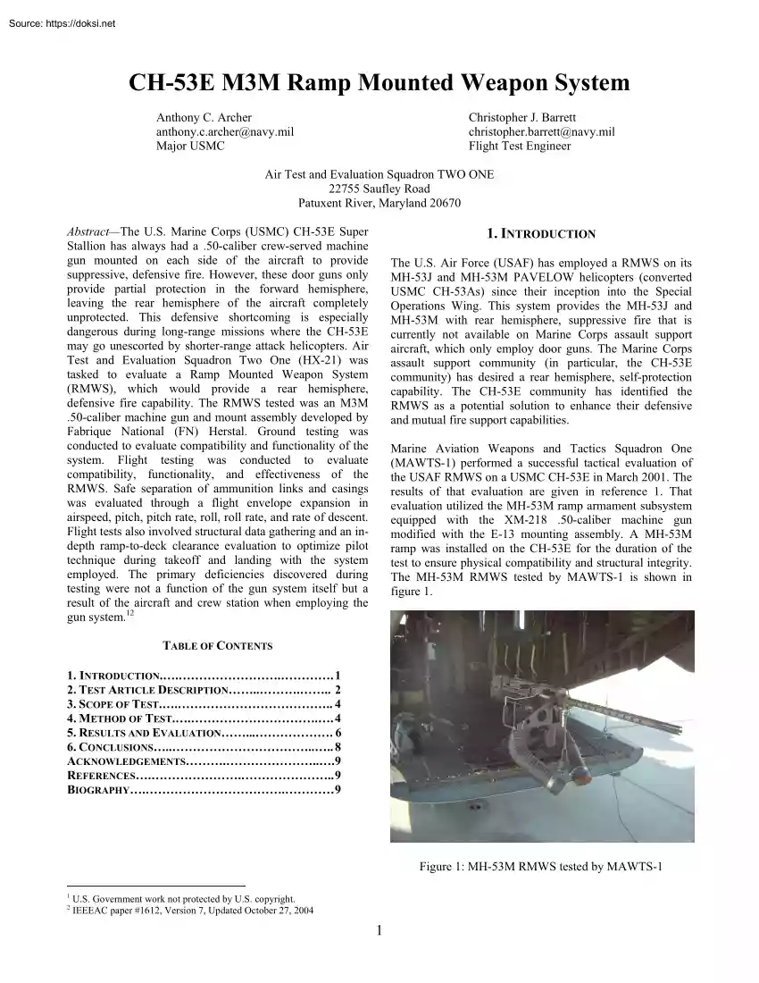
hemisphere, suppressive fire that is currently not available on Marine Corps assault support aircraft, which only employ door guns. The Marine Corps assault support community (in particular, the CH-53E community) has desired a rear hemisphere, self-protection capability. The CH-53E community has identified the RMWS as a potential solution to enhance their defensive and mutual fire support capabilities. Marine Aviation Weapons and Tactics Squadron One (MAWTS-1) performed a successful tactical evaluation of the USAF RMWS on a USMC CH-53E in March 2001. The results of that evaluation are given in reference 1. That evaluation utilized the MH-53M ramp armament subsystem equipped with the XM-218 .50-caliber machine gun modified with the E-13 mounting assembly. A MH-53M ramp was installed on the CH-53E for the duration of the test to ensure physical compatibility and structural integrity. The MH-53M RMWS tested by MAWTS-1 is shown in figure 1. TABLE OF CONTENTS 1. INTRODUCTION 1 2. TEST
ARTICLE DESCRIPTION 2 3. SCOPE OF TEST 4 4. METHOD OF TEST 4 5. RESULTS AND EVALUATION 6 6. CONCLUSIONS 8 ACKNOWLEDGEMENTS.9 REFERENCES. 9 BIOGRAPHY.9 Figure 1: MH-53M RMWS tested by MAWTS-1 1 2 U.S Government work not protected by US copyright IEEEAC paper #1612, Version 7, Updated October 27, 2004 1 The CH-53E currently uses the XM-218 .50-caliber aircraft machine gun as its crew-served weapon system. However, due to the XM-218’s age and decreasing reliability, the Marine Corps Warfighting Lab (MCWL) had been exploring possibilities for a replacement. The M3M 50-caliber machine gun, produced by FN Herstal, has an increased rate of fire and reportedly greater reliability than the XM-218. The M3M is currently in service with the United Kingdom on their Lynx and Panther helicopters. The M3M was successfully evaluated in the starboard crew personnel door of the CH-53E in January 2002. The M3M was also successfully evaluated on the UH-1N in August 2001 and October 2002 and on the
CH-46E in March and September 2002. Three General Electric T64-GE-416A engines, each capable of producing 4,380 shp at a power turbine output speed of 14,280 rpm, powered the CH-53E. The engine had antiicing systems giving the helicopter an all-weather capability. The maximum gross weight of the helicopter was 73,500 lb. A detailed description of the CH-53E is contained in the Naval Air Training and Operating Procedures Standardization (NATOPS) Flight Manual, reference 2. CH-53E, BuNo 163086 was used for these tests. The aircraft was representative of a fleet configured aircraft except for the equipment under test. The CH-53E is shown in figure 2. Despite all these efforts, a rigorous and methodical approach to integrating a machine gun-based weapon system on the ramp of a large assault helicopter had not been done. The goal of the test team was to utilize a systems engineering approach to evaluate the following issues; fit and compatibility, safe separation of expended links and
casings, airframe structural fatigue, ramp to deck clearance during flight operations with the ramp open, crew safety while operating on the ramp in-flight, and operational effectiveness. The team’s desired end-state was a full fleetwide flight clearance for the CH-53E M3M RMWS The M3M was a belt-fed, recoil-operated, air-cooled, .50caliber, crew-operated machine gun produced by FN Herstal. The M3M machine gun was designed to have a rate of fire of 950 to 1,250 rounds per minute. Expended ammunition casings were ejected downward and forward of the weapon. Expended ammunition links were ejected through a link ejection chute that ejected the links below the base of the ramp. The M3M used for the RMWS was lefthand fed The M3M interfaced with the aircraft through a modified medium pintle head (MPH). The MPH was affixed to a base plate which was mounted to a ramp interface plate through three quick disconnects for quick system removal. A 300 round ammunition can was affixed to the back
of the MPH and was connected to the M3M through a flexible ammunition feed chute. Total system weight excluding ammunition was 265 lb. Safety cables were used to prevent the ramp from lowering and to provide a visual reference that the ramp was in the proper position. The cables ran between the 5,000 lb ramp tiedown rings and the ramp uplock dogleg bolts on both port and starboard sides of the ramp. Any slack in the cables would have indicated that the ramp was not in the proper position. The RMWS underwent two design modifications at the completion of the flight testing done in July 2003 in order to correct the two deficiencies encountered. The CH-53E M3M RMWS is shown in figure 3. M3M Ramp Mounted Weapon System 2. TEST ARTICLE DESCRIPTION CH-53E Super Stallion Helicopter The Sikorsky CH-53E was an assault transport helicopter equipped with a seven-blade main rotor and a four-blade tail rotor. It was designed for land- and ship-based operation, with emergency water operating
capability. The tail rotor was canted 20 deg to the left, which provided additional lift and the ability to set the center of gravity (CG) further aft. The main gearbox was tilted 5 deg forward, which provided a level fuselage at cruising speeds. Figure 2: CH-53E Super Stallion Helicopter 2 Figure 3: FN Herstal M3M RMWS Figure 5: Five-Point Safety Harness Aerial Gunner Restraint System Test Instrumentation The gunner restraint system consisted of two 15,000 lb straps with two standard locking carabineers attached at each end of both straps. The straps were attached to the outboard 10,000 lb cargo rings at station 522. An 18,400 lb steel O-ring was used to form the attachment point for the aircrewman’s aircraft safety harness. The gunner restraint system is shown in figure 4. Onboard Video Camera System. An onboard Sony XC-555 video camera system was used to record the gun operation for postflight analysis and data documentation. A wiring harness containing power and video
ran from the camera to the instrumentation package on the port side of the aircraft in the cargo area using an existing Hi-8 mm recording package. Structural Instrumentation Structural data were obtained through the installation of 33 strain gages on the airframe, ramp, and mount structures. The data recording package consisted of a Teletronics Technology Corp’s CDAU 2012 compatible data acquisition unit, MCI-105 PCM controller, SCD-105S signal conditioning card, BLS-148 bi-level conditioning card, and Teletronics Technology Corporation SMS 2000 solid-state recorder. The data recording package is shown in figure 6. Figure 4: Gunner Restraint System Aircrew Safety Harness During a portion of the testing, the gunner operating the RMWS wore a five-point safety harness (P/N 1680EG033). KC-130 aircrew also uses this harness during aerial delivery. This harness is shown in figure 5 The remainder of the testing was done with the current helicopter aircrewmen gunner’s belt used by the
operational forces in the fleet. Aircrew operating on the ramp of the MH-53E during airborne countermine sweeping operations also use this belt. Figure 6: Data Recording Package Frangible Distance Measuring Pegs Frangible pegs were used to measure ramp-to-deck clearance. Four frangible gypsum board pegs were attached to the bottom of the ramp through a locally designed and manufactured mounting bracket. The pegs measured in length from 2 to 14 in. below the ramp bumper (in 4-in increments). The frangible pegs are shown in figure 7 3 A total of 2,000 rounds was fired during the flight on 14 November. Ramp-to-Deck Clearance Evaluation. One 15-hr ramp-todeck clearance evaluation flight was conducted on 21 November 2003. The flight crew consisted of a pilot, copilot, and two crew chiefs. The aircraft was loaded with the distance measuring peg bracket on the ramp. The RMWS was not loaded during the ramp to deck clearance evaluation to prevent possible damage to the system. The flight
was conducted at NAS Patuxent River on runway 02/20. 4. METHOD OF TEST Ground Tests Fit Tests. Fit checks were conducted to evaluate the physical compatibility of the M3M RMWS with the CH-53E. These tests evaluated the minimum clearance distances between the gun system and aircraft, human factors considerations, laser aiming sight compatibility, and clearances between bullet trajectory and the aircraft. Gun mount hard stop clearances and gun-to-store clearance measurements were taken to determine compliance with requirements in the applicable Military Standards, local ordnance Standard Operating Procedures, and Military Handbooks, references 3, 5, and 6. Instrumentation consisted of a tape measure, a plumb bob, and an inclinometer. Data were recorded on paper. The test events were documented photographically with a digital camera. Figure 7: Frangible Distance Measuring Pegs 3. SCOPE OF TEST Ground Tests Fit Tests. Two fit tests were conducted at the HX-21 hangar The fit tests were
conducted on 20 June and 12 November 2003. During the fit tests, the aircraft was configured with the RMWS on the ramp. Ground Firing Tests. Two ground firing tests were conducted at the Ordnance Support Team firing tunnel. The ground firing tests were conducted on 27 June and 13 November 2003. During the ground firing test on 27 June, 525 rounds were fired to complete the test matrix and an additional 275 rounds were fired for aerial gunner training. During the ground firing test on 13 November, 200 rounds were fired to complete the test matrix and an additional 200 rounds were fired for gunner training. Aircraft loading consisted of the RMWS on the ramp. Ground Firing Tests. Ground firing tests were conducted to evaluate the physical compatibility and functionality of the M3M RMWS on the CH-53E, and gather structural load data. Additionally, the ground firing evaluated the spent casing trajectory to determine suitability for flight testing. A digital video recorder was used to
record the spent casing trajectory from the M3M. These tests were performed in accordance with references 4 through 9. Flight Tests Flight Tests Captive Carriage Rehearsal Flight. One 13-hr captive carriage rehearsal flight was conducted on 7 July 2003. The flight crew consisted of a pilot, copilot, and three crewmen. The aircraft was loaded with the RMWS on the ramp. The flight was conducted on the Atlantic Test Range, Patuxent River, Maryland, in the vicinity of Hannibal Target, R-4005 South. Captive Carriage Rehearsal Flight. A captive carriage rehearsal flight was conducted to familiarize the aircrew with the test points to be flown during the live fire flight testing. This was done in order to reduce the risk involved in firing a new gun system from a new aircrew position for the first time. Two live fire tests were conducted. One 38-hr flight was conducted on 8 July 2003 and one 2.3-hr flight was conducted on 14 November 2003. The flight crews consisted of a pilot, copilot,
and three crewmen. The aircraft was configured with the RMWS on the ramp. Both flights were conducted on the Atlantic Test Range, Patuxent River, Maryland, in the vicinity of Hannibal Target, R-4005 South. A total of 3,800 rounds was fired during the flight on 8 July. Live Fire Flight Test. Live fire flight testing was conducted to evaluate the compatibility, functionality, and effectiveness of the M3M RMWS. Safe separation of expended ammo links and casings was evaluated through a flight envelope expansion in airspeed, pitch, pitch rate, roll, roll rate, and rate of descent. Structural data were gathered during normal operational maneuvers and maximum load maneuvers. Flight regimes and maneuvers included hover, 4 forward flight up to 150 KIAS, turns up to 60 deg angle of bank, pitchups up to 45 deg, descents up to 2,000 ft/min, level quick stops, break turns, bunts, and simulated tactical takeoffs. The safe separation test matrix completed on 8 July 2003 is shown in table 1. The
structural data gathering test matrix completed on 14 November 2003 is included as table 2. Table 1: In-Flight Firing Test Points for Safe Separation Testing Airspeed (KIAS) Altitude (ft AGL) Bank Angle (deg) Pitch Angle (deg) Pitch Rate (deg/sec) Rate of Descent (ft/min) Hover 0 2001,200 As Required As Required 0 0 Level Forward Flight 40 80 120 150 5001,000 0+5 0+5 0 0 Coordinated Left Turns 80 120 150 5001,000 30, 45, 60 30, 45, 60 30, 45 0+5 0 Coordinated Right Turns 80 120 150 5001,000 30, 45, 60 30, 45, 60 30, 45 0+5 Quickstops 80 5001,000 0+3 Descents 80 0+5 Left Break Turn 120 5001,000 Right Break Turn 120 Bunt Simulated Tactical Takeoff Flight Maneuver Gun Azimuth Straight Aft Full Starboard Full Port Max Elevation Max Depression As Required to Track Target off Port Side As Required to Track Target 0 As Required to Track Target As Required to Track Target 0 0 As Required to Track Target As Required to Track Target 0-30
5, 10, 15 0 As Required to Track Target As Required to Track Target As Required As Required 250, 500, 1000, 1500, 2000 As Required to Track Target As Required to Track Target 0-60 As Required As Required 0 As Required to Track Target As Required to Track Target 5001,000 0-60 As Required As Required 0 As Required to Track Target As Required to Track Target 120 5001,000 0+3 As Required As Required As Required 0-120 1001,000 0+3 As Required As Required N/A As Required to Track Target As Required to Track Target As Required to Track Target As Required to Track Target 5003,000 Gun Elevation Table 2. In-Flight Firing Test Points for Structural Data Gathering Flight Maneuver Airspeed (KIAS) Altitude (ft AGL) Bank Angle (deg) Pitch Angle (deg) Gun Azimuth Gun Elevation Straight Aft Full Starboard Full Port Max Elevation Max Depression Hover/Slow Speed Flight < 30 200-1,200 As Required As Required Level Forward Flight 120 500-1,000 0+5
As Required As Required to Track Target As Required to Track Target Left Break Turn 120 500-1,000 0-60 As Required As Required to Track Target As Required to Track Target Right Break Turn 120 500-1,000 0-60 As Required As Required to Track Target As Required to Track Target Quickstops 120 500-1,000 0+3 0 – 45 As Required to Track Target As Required to Track Target Simulated Tactical Takeoff 0-120 100-1,000 0+3 As Required As Required to Track Target As Required to Track Target 5 Ramp-to-Deck Clearance Evaluation. A ramp-to-deck clearance evaluation flight was conducted to evaluate rampto-deck clearance during takeoff and landing over a level surface. Clearance was evaluated at three ramp positions; level, -2 deg, and -4 deg. Aircraft gross weight was between 51,500 and 54,250 lb and CG varied from 350.70 to 353.1 in forward Landing profiles included landing from a hover, landing with 5 kt forward groundspeed, landing with 4 kts rearward
groundspeed, and steep approaches to a nohover landing. All takeoffs terminated in a 5 to 10 ft hover Ramp-to-deck clearance evaluation test points are shown in table 3. Table 3: In-Flight Nonfiring Test Points for Ramp-to-Deck Clearance Evaluation Altitude (ft AGL) 0-25 Groundspeed 0 Ramp Position Level Normal landing from a 25 ft hover 25-0 0 Level Takeoff 0-25 0 -2 deg Normal landing from a 25 ft hover 25-0 0 -2 deg Takeoff 0-25 0 -2 deg Normal landing from a 25 ft hover 25-0 5 kt forward -2 deg Takeoff 0-25 0 -2 deg Normal landing from a 25 ft hover 25-0 5 kt rearward -2 deg Takeoff 0-25 0 - 4 deg Normal landing from 25 ft hover 25-0 0 -4 deg Takeoff 0-25 0 -4 deg Normal landing from 25 ft hover 25-0 5 kt forward -4 deg Takeoff 0-25 0 -4 deg Normal landing from 25 ft hover 25-0 5 kt rearward -4 deg No hover landing from steep approach 200-0 5 kt forward Level -2 deg -4 deg Flight Maneuver Takeoff fire capability. Ramp
positions in which the cables are not taut will cause the maximum elevation stop to be ineffective in preventing projectile impacts to the aircraft structure. RMWS should only be operated when the safety cables are taut. 5. RESULTS AND EVALUATION Physical Fit and Compatibility Results Field of Fire. The M3M RMWS field of fire was evaluated for physical compatibility. Store-to-aircraft and projectileto-aircraft clearances were satisfactory and complied with the guidelines listed in MIL-STD-1289D, reference 3. Azimuth field of fire was from 90 deg port to 90 deg starboard. Elevation field of fire was from –4 to –74 deg Elevation angles were measured relative to the aircraft cabin floor. Taut safety cables indicated that the ramp was in the RMWS operational configuration (ramp at –4 deg). This field of fire will allow the CH-53E to engage targets to the sides and rear of the aircraft after the side/door mounted crew-served guns have reached their maximum aft azimuth stops. This
will result in an increased defensive suppressive Laser Aiming Sight Compatibility. The M3M RMWS was evaluated for compatibility with the GCP-2A laser aiming sight. Clearance between the laser bore and aircraft structure was evaluated throughout the field of fire. With the gun at full elevation, with the ramp at –4 deg, 1 in. existed between the laser bore and aircraft dorsal fin. This clearance may be diminished with gun firing, due to cradle rocking, or if the operator does not focus the laser beam correctly. This may cause a diffuse reflection of the beam into the cabin. Although this diffuse reflection does not cause an eyerelated safety concern, this diffuse reflection may cause 6 night vision goggle blooming. Eye-safety would need to be reevaluated if this system is desired for aircraft with glossy paint schemes, which may cause a specular reflection instead of a diffuse reflection. 7 Flight Test Results to quickly move forward in the cabin and into a seat in the
event of an anticipated crash or hard landing. Safe Separation of Ammunition Links and Casings. The M3M RMWS was evaluated for safe separation of ammunition links and casings. In a 200-ft hover with the gun at full starboard and maximum elevation, one link impacted the bottom of the tail pylon directly aft of the ramp during a 25-round burst. This impact did not damage the aircraft or affect the safety of flight. The impact was a result of circulating airflow aft of the ramp. The airflow caused the link ejection chute to move to a horizontal position and the link to be blown upward into the tail-boom structure after exiting the chute. This impact occurred during the first flight test on 8 July 2003. The link ejection chute was subsequently redesigned so that it was affixed in the vertical position. No further link impacts were observed during the second test flight at the same test condition. During turns and quick stops at 150 KIAS, approximately 1 in 10 ammunition links impacted the
tailskid. These impacts did not damage the aircraft or affect the safety of flight. The M3M RMWS demonstrated safe separation during all maneuvers up to the aircraft’s NATOPS limits. Ramp-to-Deck Clearance. The aircraft is normally operated with the ramp closed. With the M3M RMWS installed, the ramp must be open to accommodate the desired field of fire. An evaluation was conducted during ground testing, live fire testing, and a ramp-to-deck clearance flight with the ramp at three ramp positions; level, -2 deg, and -4 deg. Takeoffs terminated in a 5 to 10 ft hover. Profiles included landing from a 5-ft hover, landing with 5 kt forward groundspeed, landing with 3-4 kt rearward groundspeed, and a steep approach terminating in a no-hover landing. All profiles were flown at each of the three ramp positions. The CH-53E M3M RMWS was not designed to allow the ramp to be positioned in the normal closed configuration for takeoff and landing. With the ramp at the -4 deg position, 130 in of
clearance were measured between the ramp bumper and a level surface with the helicopter static and with a gross weight of 54,300 lb. On the same surface and at the same weight, landing from a hover, 8-10 in. of clearance was measured between the ramp bumpers and the deck. More than 10 in. were measured when landing with 5 kts of forward groundspeed. The minimum clearance measured between the ramp bumper and the deck was with 3-4 kt of rearward groundspeed where 6-8 in. of clearance was measured. The CH-53E ramp system incorporated a floating ramp capability in the open position, in that relief valves were provided in the pressure lines of each actuating cylinder. If the ramp should strike the ground, the relief valves would cause the hydraulic pressure to bypass and allow the ramp to move toward the closed position until the force was removed. This feature was designed to lessen the possibility of ramp or actuating cylinder damage. When the ramp is in the RMWS operational configuration
(-4 deg), certain combinations of terrain, aircraft attitude, and pitch rate will cause ramp-to-ground contact and could result in damage to the ramp structure. Inadequate clearance between the ramp in the M3M RMWS configuration and the ground is a deficiency that should be corrected as soon as practicable. Recommend a caution be added to the CH-53E NATOPS Flight Manual emphasizing caution being exercised during takeoff and landing when the M3M RMWS is installed. Additionally, recommend raising the ramp to the level position for all takeoffs and landings when tactical employment of the RMWS is not foreseen. Further testing is recommended at aft CGs to determine the effect, if any, on ramp-to-deck clearance. Operational Effectiveness. The M3M RMWS was qualitatively evaluated for operational effectiveness for the combat assault support mission. The evaluation was conducted during ground and flight testing. Aircrewmen were able to effectively employ the weapon against a stationary target
throughout the CH-53E NATOPS flight envelope. Steady state flight maneuvers provided no challenges to effectively employing the weapon against the designated target within the weapon’s field of fire. Dynamic maneuvers, although challenging due to the onset of vertical acceleration forces (“g”), did not prevent the RMWS operators from putting effective fires on the target. Aggressive break turns away from the target proved to be the most difficult, however, all RMWS operators were able to fire two or three, 30 to 50 round bursts on the target during the maneuver. The RMWS will give the CH-53E a rear hemisphere, suppressive fire capability. RMWS Crew Position. The evaluation was conducted during ground testing and both dry fire and live fire flight tests. When operating the RMWS on the ramp the crewman was not provided with any means of protection from vertical impacts. The RMWS crew position consisted of an aircrew restraint system designed to protect the crewmen from falling off
the ramp, but provided no crash protection. The inadequate protection at the RMWS crew position will cause serious injury or death to the crewman in the event of a crash or hard landing. The inadequate crash protection provided at the RMWS crewman position is a hazard that must be corrected as soon as possible. Recommend having the ramp gun operator seated and strapped into the troop seats for all nontactical takeoffs and landings when the RMWS is not being employed until a ramp crew mobility system can be developed that allows the gunner the ability Aircrew Safety Harness. The five-point aircrew safety harness was qualitatively evaluated for user safety. The quick-release for the five-point harness is in the back, as opposed to the current USMC gunner’s belt, which releases in the front. The change in quick-release location will cause an increase in time needed for a crewman trained on the current gunner’s belt to release him or herself from the aircraft during an emergency. The
harness was also not 8 adjustable enough to accommodate the 5’7” 140-lb test gunner. A poorly fitting safety harness may cause injury to the gunner if he or she falls from the ramp. The current aircrew gunner’s belt was also qualitatively evaluated. The test gunner felt safe and secure operating on the ramp of the CH-53E while employing the weapon system wearing the current aircrew gunner’s belt. the input to the ramp and structure. Based on the above analysis and experience with other aircraft structures, no damage is anticipated and an inspection will be instituted to check for material cracking, working rivets and loose fasteners, and other signs of damage every 6 months, coincident with the current cabin floor structure inspection. 6. CONCLUSIONS Structural Fatigue. A structural fatigue analysis was done utilizing Finite Element Analysis (FEA) combined with strain gage data recorded during flight testing. The fatigue was addressed by two approaches; the first was to
look at the maximum and minimum strains and note with what stresses the observed strains corresponded. This information was then compared to a classic S-N curve to determine the fatigue life. The oscillatory strains that resulted were small and determined not to produce fatigue damage. The second method fatigue was investigated applied the recorded strains to nodes located where strain gages were placed on the structure. These recorded strains were then used as inputs to the FEA model. This method displayed a high harmonic response in the 150-350 Hz range, which was well above the 17-20 Hz firing rate of the weapon. The harmonic response was observed to be well damped. Potential high frequencies may be in areas where strain gages were not present. The model used excited at a constant high frequency, which does not accurately represent the resonance that was observed to dampen quickly between weapon firings. While this indicates possible problem areas, it does not exactly match The M3M
RMWS as installed on the CH-53E provided the desired rear hemisphere suppressive and defensive fire capability sought by the USMC assault support community. The field of fire before and after installation of RMWS is shown in figures 8 and 9. Although some deficiencies were identified that required engineering or aircrew training solutions, the system is suitable as tested with the following findings: 1. Fit and Compatibility Mounting of the M3M RMWS in the CH-53E requires the installation of a base plate, removable interface plate, mount assembly, and the M3M gun. Three NORCO fittings must be removed from the ramp and rethreaded to accept adapter bolts. Once the system is installed, the system can be deconfigured by two crewmen to allow the loading and unloading of cargo and vehicles in less than 30 sec. Only 50 sec is needed to return the system to its operational configuration. It is possible for one crewman to complete the task, but more time is required. Figure 8: Azimuth Field of
Fire without and with RMWS 9 Figure 9: Elevation Field of Fire with RMWS 2. Safe Store Separation Of 3,800 rounds fired during the first live fire flight, only 1 ammunition link impacted the structure of the aircraft. This was attributed to the link REFERENCES ejection chute moving to the horizontal position due to [1] airflow. The link ejection chute was redesigned and no links Tactical Development and Evaluation Final Report were observed impacting the aircraft structure during the Qualitative Assessment of the Ramp-Mounted .50 cal second live fire flight in which 2,000 rounds were expended. Machine Gun on the CH-53E, of 28 Nov 2001. [2] The M3M RMWS demonstrated safe separation during all NATOPS Flight Manual, Navy Model CH-53E maneuvers up to the aircraft’s flight manual limits. Helicopter, A1-H53BE-NFM-000, of 15 Apr 2001. [3] 3. Structural Fatigue Analysis Analysis completed to date Military Standard MIL-STD-1289D, Requirements indicates no structural damage to the ramp or
aircraft for Airborne Stores Ground Fit and Compatibility, of 22 Sep structure is anticipated. An inspection coincident with the 2003. [4[ current 6-month ramp inspection is the only action planned TESTWINGLANTINST 8020.1C, Ordnance Systems at this time. Standard Operating Procedures, of Apr 2003. [5] 4. Ramp-to-Deck Clearance The normal configuration for Military Handbook MIL-HDBK-244A, Guide to the helicopter is to have the ramp in the up and closed Aircraft/Stores Compatibility, of 6 Apr 1990. [6] position for flight operations. Installation of the RMWS Military Handbook MIL-HDBK-1763, Aircraft/Stores requires the ramp to be open at approximately 4 deg below Compatibility: Systems Engineering Data Requirements and level. With the ramp in this position, it is possible to have Test Procedures, of 15 Jun 1998. [7] the ramp structure impact the terrain before the main NASINST 8600.1A, NAVAIRTESTCEN Standard landing gear or the tailskid. Numerous takeoffs and landings Armament Test
Manual, of 14 Sep 1989. [8] were conducted and recorded with the ramp clearance never NAVAIRWARCENACDIVINST 13034.1B, Flight less than 6 in., even in rearward flight The ramp has two Clearance Policies, Procedures, and Responsibilities, of 24 fairly robust rubber bumpers installed to absorb any Oct 2000. [9] inadvertent ground contact. The ramp hydraulic cylinders NASPAXRIVINST 3710.5T, Naval Air Station Air were designed to absorb some amount of ramp to ground Operations Manual, of 3 Jun 2002. contact. Although a deficiency, training and increased situational awareness due to having a crewman on the ramp BIOGRAPHY should avoid ramp strikes with the RMWS installed. 5. RMWS Crew Position The lack of an energy Chris joined the Naval Air Warfare attenuating system for the gunner operating the M3M Center Aircraft Division (NAWCAD) at RMWS is a deficiency. Although the crewman is safest NAS Patuxent River, Maryland in July when occupying a troop seat for takeoff and landing, this 2002 after
graduating from Virginia Tech must be balanced with the increased situational awareness with a B.S in Aerospace Engineering and aircraft protection that is gained by a crewman manning He is a flight test engineer in the Air the gun, positioned on the ramp. During brownout or Vehicle/Stores Compatibility Division. His flight test whiteout conditions when trying to land in the desert or projects have included testing 7.62 mm and 50 caliber arctic environment, the crewman on the ramp may be able to crew-served gun systems on U.S Navy, US Marine Corps, maintain visual reference when the rest of the crew cannot. and U.S Coast Guard helicopters He is currently a flight It will be up to unit and aircraft commanders to do the test engineer for the USMC H-1 Upgrades program testing proper Operational Risk Management to consider the missile, rocket, countermeasure, and gun system benefits and risks associated with this new crew position. compatibility on the AH-1Z Cobra and UH-1Y Huey. 6.
Operational Suitability The M3M RMWS as installed in the CH-53E provides the required rear hemisphere Major Archer is the Operations Officer suppressive/defensive fire capability for the combat assault of Air Test and Evaluation Squadron support mission. Two-One (HX-21). He has served as the Project Officer for the Ground Proximity Warning System, which is being integrated into Navy and Marine Corps transport helicopters as well as many of the systems that make up the Aircraft Survivability Suite on the CH-53E and CH-53D. Major Archer has served in numerous billets during two fleet marine force tours and has taken part in numerous contingency operations across the globe, including Bosnia and Somalia. He has a BS in Aerospace Engineering from ACKNOWLEDGEMENTS The MCWL sponsored this work. Other organizations helping support this project were PMA-242, Defensive Suppression Systems, PMA-261, H-53 Program Office, and HX-21. The authors thank all those who contributed to this project, to
include engineering, range and maintenance personnel, pilots, and flight crew. 10 the University of Florida and is a graduate of the United States Naval Test Pilot School. 11
by Fabrique National (FN) Herstal. Ground testing was conducted to evaluate compatibility and functionality of the system. Flight testing was conducted to evaluate compatibility, functionality, and effectiveness of the RMWS. Safe separation of ammunition links and casings was evaluated through a flight envelope expansion in airspeed, pitch, pitch rate, roll, roll rate, and rate of descent. Flight tests also involved structural data gathering and an indepth ramp-to-deck clearance evaluation to optimize pilot technique during takeoff and landing with the system employed. The primary deficiencies discovered during testing were not a function of the gun system itself but a result of the aircraft and crew station when employing the gun system.12 1. INTRODUCTION The U.S Air Force (USAF) has employed a RMWS on its MH-53J and MH-53M PAVELOW helicopters (converted USMC CH-53As) since their inception into the Special Operations Wing. This system provides the MH-53J and MH-53M with rear
hemisphere, suppressive fire that is currently not available on Marine Corps assault support aircraft, which only employ door guns. The Marine Corps assault support community (in particular, the CH-53E community) has desired a rear hemisphere, self-protection capability. The CH-53E community has identified the RMWS as a potential solution to enhance their defensive and mutual fire support capabilities. Marine Aviation Weapons and Tactics Squadron One (MAWTS-1) performed a successful tactical evaluation of the USAF RMWS on a USMC CH-53E in March 2001. The results of that evaluation are given in reference 1. That evaluation utilized the MH-53M ramp armament subsystem equipped with the XM-218 .50-caliber machine gun modified with the E-13 mounting assembly. A MH-53M ramp was installed on the CH-53E for the duration of the test to ensure physical compatibility and structural integrity. The MH-53M RMWS tested by MAWTS-1 is shown in figure 1. TABLE OF CONTENTS 1. INTRODUCTION 1 2. TEST
ARTICLE DESCRIPTION 2 3. SCOPE OF TEST 4 4. METHOD OF TEST 4 5. RESULTS AND EVALUATION 6 6. CONCLUSIONS 8 ACKNOWLEDGEMENTS.9 REFERENCES. 9 BIOGRAPHY.9 Figure 1: MH-53M RMWS tested by MAWTS-1 1 2 U.S Government work not protected by US copyright IEEEAC paper #1612, Version 7, Updated October 27, 2004 1 The CH-53E currently uses the XM-218 .50-caliber aircraft machine gun as its crew-served weapon system. However, due to the XM-218’s age and decreasing reliability, the Marine Corps Warfighting Lab (MCWL) had been exploring possibilities for a replacement. The M3M 50-caliber machine gun, produced by FN Herstal, has an increased rate of fire and reportedly greater reliability than the XM-218. The M3M is currently in service with the United Kingdom on their Lynx and Panther helicopters. The M3M was successfully evaluated in the starboard crew personnel door of the CH-53E in January 2002. The M3M was also successfully evaluated on the UH-1N in August 2001 and October 2002 and on the
CH-46E in March and September 2002. Three General Electric T64-GE-416A engines, each capable of producing 4,380 shp at a power turbine output speed of 14,280 rpm, powered the CH-53E. The engine had antiicing systems giving the helicopter an all-weather capability. The maximum gross weight of the helicopter was 73,500 lb. A detailed description of the CH-53E is contained in the Naval Air Training and Operating Procedures Standardization (NATOPS) Flight Manual, reference 2. CH-53E, BuNo 163086 was used for these tests. The aircraft was representative of a fleet configured aircraft except for the equipment under test. The CH-53E is shown in figure 2. Despite all these efforts, a rigorous and methodical approach to integrating a machine gun-based weapon system on the ramp of a large assault helicopter had not been done. The goal of the test team was to utilize a systems engineering approach to evaluate the following issues; fit and compatibility, safe separation of expended links and
casings, airframe structural fatigue, ramp to deck clearance during flight operations with the ramp open, crew safety while operating on the ramp in-flight, and operational effectiveness. The team’s desired end-state was a full fleetwide flight clearance for the CH-53E M3M RMWS The M3M was a belt-fed, recoil-operated, air-cooled, .50caliber, crew-operated machine gun produced by FN Herstal. The M3M machine gun was designed to have a rate of fire of 950 to 1,250 rounds per minute. Expended ammunition casings were ejected downward and forward of the weapon. Expended ammunition links were ejected through a link ejection chute that ejected the links below the base of the ramp. The M3M used for the RMWS was lefthand fed The M3M interfaced with the aircraft through a modified medium pintle head (MPH). The MPH was affixed to a base plate which was mounted to a ramp interface plate through three quick disconnects for quick system removal. A 300 round ammunition can was affixed to the back
of the MPH and was connected to the M3M through a flexible ammunition feed chute. Total system weight excluding ammunition was 265 lb. Safety cables were used to prevent the ramp from lowering and to provide a visual reference that the ramp was in the proper position. The cables ran between the 5,000 lb ramp tiedown rings and the ramp uplock dogleg bolts on both port and starboard sides of the ramp. Any slack in the cables would have indicated that the ramp was not in the proper position. The RMWS underwent two design modifications at the completion of the flight testing done in July 2003 in order to correct the two deficiencies encountered. The CH-53E M3M RMWS is shown in figure 3. M3M Ramp Mounted Weapon System 2. TEST ARTICLE DESCRIPTION CH-53E Super Stallion Helicopter The Sikorsky CH-53E was an assault transport helicopter equipped with a seven-blade main rotor and a four-blade tail rotor. It was designed for land- and ship-based operation, with emergency water operating
capability. The tail rotor was canted 20 deg to the left, which provided additional lift and the ability to set the center of gravity (CG) further aft. The main gearbox was tilted 5 deg forward, which provided a level fuselage at cruising speeds. Figure 2: CH-53E Super Stallion Helicopter 2 Figure 3: FN Herstal M3M RMWS Figure 5: Five-Point Safety Harness Aerial Gunner Restraint System Test Instrumentation The gunner restraint system consisted of two 15,000 lb straps with two standard locking carabineers attached at each end of both straps. The straps were attached to the outboard 10,000 lb cargo rings at station 522. An 18,400 lb steel O-ring was used to form the attachment point for the aircrewman’s aircraft safety harness. The gunner restraint system is shown in figure 4. Onboard Video Camera System. An onboard Sony XC-555 video camera system was used to record the gun operation for postflight analysis and data documentation. A wiring harness containing power and video
ran from the camera to the instrumentation package on the port side of the aircraft in the cargo area using an existing Hi-8 mm recording package. Structural Instrumentation Structural data were obtained through the installation of 33 strain gages on the airframe, ramp, and mount structures. The data recording package consisted of a Teletronics Technology Corp’s CDAU 2012 compatible data acquisition unit, MCI-105 PCM controller, SCD-105S signal conditioning card, BLS-148 bi-level conditioning card, and Teletronics Technology Corporation SMS 2000 solid-state recorder. The data recording package is shown in figure 6. Figure 4: Gunner Restraint System Aircrew Safety Harness During a portion of the testing, the gunner operating the RMWS wore a five-point safety harness (P/N 1680EG033). KC-130 aircrew also uses this harness during aerial delivery. This harness is shown in figure 5 The remainder of the testing was done with the current helicopter aircrewmen gunner’s belt used by the
operational forces in the fleet. Aircrew operating on the ramp of the MH-53E during airborne countermine sweeping operations also use this belt. Figure 6: Data Recording Package Frangible Distance Measuring Pegs Frangible pegs were used to measure ramp-to-deck clearance. Four frangible gypsum board pegs were attached to the bottom of the ramp through a locally designed and manufactured mounting bracket. The pegs measured in length from 2 to 14 in. below the ramp bumper (in 4-in increments). The frangible pegs are shown in figure 7 3 A total of 2,000 rounds was fired during the flight on 14 November. Ramp-to-Deck Clearance Evaluation. One 15-hr ramp-todeck clearance evaluation flight was conducted on 21 November 2003. The flight crew consisted of a pilot, copilot, and two crew chiefs. The aircraft was loaded with the distance measuring peg bracket on the ramp. The RMWS was not loaded during the ramp to deck clearance evaluation to prevent possible damage to the system. The flight
was conducted at NAS Patuxent River on runway 02/20. 4. METHOD OF TEST Ground Tests Fit Tests. Fit checks were conducted to evaluate the physical compatibility of the M3M RMWS with the CH-53E. These tests evaluated the minimum clearance distances between the gun system and aircraft, human factors considerations, laser aiming sight compatibility, and clearances between bullet trajectory and the aircraft. Gun mount hard stop clearances and gun-to-store clearance measurements were taken to determine compliance with requirements in the applicable Military Standards, local ordnance Standard Operating Procedures, and Military Handbooks, references 3, 5, and 6. Instrumentation consisted of a tape measure, a plumb bob, and an inclinometer. Data were recorded on paper. The test events were documented photographically with a digital camera. Figure 7: Frangible Distance Measuring Pegs 3. SCOPE OF TEST Ground Tests Fit Tests. Two fit tests were conducted at the HX-21 hangar The fit tests were
conducted on 20 June and 12 November 2003. During the fit tests, the aircraft was configured with the RMWS on the ramp. Ground Firing Tests. Two ground firing tests were conducted at the Ordnance Support Team firing tunnel. The ground firing tests were conducted on 27 June and 13 November 2003. During the ground firing test on 27 June, 525 rounds were fired to complete the test matrix and an additional 275 rounds were fired for aerial gunner training. During the ground firing test on 13 November, 200 rounds were fired to complete the test matrix and an additional 200 rounds were fired for gunner training. Aircraft loading consisted of the RMWS on the ramp. Ground Firing Tests. Ground firing tests were conducted to evaluate the physical compatibility and functionality of the M3M RMWS on the CH-53E, and gather structural load data. Additionally, the ground firing evaluated the spent casing trajectory to determine suitability for flight testing. A digital video recorder was used to
record the spent casing trajectory from the M3M. These tests were performed in accordance with references 4 through 9. Flight Tests Flight Tests Captive Carriage Rehearsal Flight. One 13-hr captive carriage rehearsal flight was conducted on 7 July 2003. The flight crew consisted of a pilot, copilot, and three crewmen. The aircraft was loaded with the RMWS on the ramp. The flight was conducted on the Atlantic Test Range, Patuxent River, Maryland, in the vicinity of Hannibal Target, R-4005 South. Captive Carriage Rehearsal Flight. A captive carriage rehearsal flight was conducted to familiarize the aircrew with the test points to be flown during the live fire flight testing. This was done in order to reduce the risk involved in firing a new gun system from a new aircrew position for the first time. Two live fire tests were conducted. One 38-hr flight was conducted on 8 July 2003 and one 2.3-hr flight was conducted on 14 November 2003. The flight crews consisted of a pilot, copilot,
and three crewmen. The aircraft was configured with the RMWS on the ramp. Both flights were conducted on the Atlantic Test Range, Patuxent River, Maryland, in the vicinity of Hannibal Target, R-4005 South. A total of 3,800 rounds was fired during the flight on 8 July. Live Fire Flight Test. Live fire flight testing was conducted to evaluate the compatibility, functionality, and effectiveness of the M3M RMWS. Safe separation of expended ammo links and casings was evaluated through a flight envelope expansion in airspeed, pitch, pitch rate, roll, roll rate, and rate of descent. Structural data were gathered during normal operational maneuvers and maximum load maneuvers. Flight regimes and maneuvers included hover, 4 forward flight up to 150 KIAS, turns up to 60 deg angle of bank, pitchups up to 45 deg, descents up to 2,000 ft/min, level quick stops, break turns, bunts, and simulated tactical takeoffs. The safe separation test matrix completed on 8 July 2003 is shown in table 1. The
structural data gathering test matrix completed on 14 November 2003 is included as table 2. Table 1: In-Flight Firing Test Points for Safe Separation Testing Airspeed (KIAS) Altitude (ft AGL) Bank Angle (deg) Pitch Angle (deg) Pitch Rate (deg/sec) Rate of Descent (ft/min) Hover 0 2001,200 As Required As Required 0 0 Level Forward Flight 40 80 120 150 5001,000 0+5 0+5 0 0 Coordinated Left Turns 80 120 150 5001,000 30, 45, 60 30, 45, 60 30, 45 0+5 0 Coordinated Right Turns 80 120 150 5001,000 30, 45, 60 30, 45, 60 30, 45 0+5 Quickstops 80 5001,000 0+3 Descents 80 0+5 Left Break Turn 120 5001,000 Right Break Turn 120 Bunt Simulated Tactical Takeoff Flight Maneuver Gun Azimuth Straight Aft Full Starboard Full Port Max Elevation Max Depression As Required to Track Target off Port Side As Required to Track Target 0 As Required to Track Target As Required to Track Target 0 0 As Required to Track Target As Required to Track Target 0-30
5, 10, 15 0 As Required to Track Target As Required to Track Target As Required As Required 250, 500, 1000, 1500, 2000 As Required to Track Target As Required to Track Target 0-60 As Required As Required 0 As Required to Track Target As Required to Track Target 5001,000 0-60 As Required As Required 0 As Required to Track Target As Required to Track Target 120 5001,000 0+3 As Required As Required As Required 0-120 1001,000 0+3 As Required As Required N/A As Required to Track Target As Required to Track Target As Required to Track Target As Required to Track Target 5003,000 Gun Elevation Table 2. In-Flight Firing Test Points for Structural Data Gathering Flight Maneuver Airspeed (KIAS) Altitude (ft AGL) Bank Angle (deg) Pitch Angle (deg) Gun Azimuth Gun Elevation Straight Aft Full Starboard Full Port Max Elevation Max Depression Hover/Slow Speed Flight < 30 200-1,200 As Required As Required Level Forward Flight 120 500-1,000 0+5
As Required As Required to Track Target As Required to Track Target Left Break Turn 120 500-1,000 0-60 As Required As Required to Track Target As Required to Track Target Right Break Turn 120 500-1,000 0-60 As Required As Required to Track Target As Required to Track Target Quickstops 120 500-1,000 0+3 0 – 45 As Required to Track Target As Required to Track Target Simulated Tactical Takeoff 0-120 100-1,000 0+3 As Required As Required to Track Target As Required to Track Target 5 Ramp-to-Deck Clearance Evaluation. A ramp-to-deck clearance evaluation flight was conducted to evaluate rampto-deck clearance during takeoff and landing over a level surface. Clearance was evaluated at three ramp positions; level, -2 deg, and -4 deg. Aircraft gross weight was between 51,500 and 54,250 lb and CG varied from 350.70 to 353.1 in forward Landing profiles included landing from a hover, landing with 5 kt forward groundspeed, landing with 4 kts rearward
groundspeed, and steep approaches to a nohover landing. All takeoffs terminated in a 5 to 10 ft hover Ramp-to-deck clearance evaluation test points are shown in table 3. Table 3: In-Flight Nonfiring Test Points for Ramp-to-Deck Clearance Evaluation Altitude (ft AGL) 0-25 Groundspeed 0 Ramp Position Level Normal landing from a 25 ft hover 25-0 0 Level Takeoff 0-25 0 -2 deg Normal landing from a 25 ft hover 25-0 0 -2 deg Takeoff 0-25 0 -2 deg Normal landing from a 25 ft hover 25-0 5 kt forward -2 deg Takeoff 0-25 0 -2 deg Normal landing from a 25 ft hover 25-0 5 kt rearward -2 deg Takeoff 0-25 0 - 4 deg Normal landing from 25 ft hover 25-0 0 -4 deg Takeoff 0-25 0 -4 deg Normal landing from 25 ft hover 25-0 5 kt forward -4 deg Takeoff 0-25 0 -4 deg Normal landing from 25 ft hover 25-0 5 kt rearward -4 deg No hover landing from steep approach 200-0 5 kt forward Level -2 deg -4 deg Flight Maneuver Takeoff fire capability. Ramp
positions in which the cables are not taut will cause the maximum elevation stop to be ineffective in preventing projectile impacts to the aircraft structure. RMWS should only be operated when the safety cables are taut. 5. RESULTS AND EVALUATION Physical Fit and Compatibility Results Field of Fire. The M3M RMWS field of fire was evaluated for physical compatibility. Store-to-aircraft and projectileto-aircraft clearances were satisfactory and complied with the guidelines listed in MIL-STD-1289D, reference 3. Azimuth field of fire was from 90 deg port to 90 deg starboard. Elevation field of fire was from –4 to –74 deg Elevation angles were measured relative to the aircraft cabin floor. Taut safety cables indicated that the ramp was in the RMWS operational configuration (ramp at –4 deg). This field of fire will allow the CH-53E to engage targets to the sides and rear of the aircraft after the side/door mounted crew-served guns have reached their maximum aft azimuth stops. This
will result in an increased defensive suppressive Laser Aiming Sight Compatibility. The M3M RMWS was evaluated for compatibility with the GCP-2A laser aiming sight. Clearance between the laser bore and aircraft structure was evaluated throughout the field of fire. With the gun at full elevation, with the ramp at –4 deg, 1 in. existed between the laser bore and aircraft dorsal fin. This clearance may be diminished with gun firing, due to cradle rocking, or if the operator does not focus the laser beam correctly. This may cause a diffuse reflection of the beam into the cabin. Although this diffuse reflection does not cause an eyerelated safety concern, this diffuse reflection may cause 6 night vision goggle blooming. Eye-safety would need to be reevaluated if this system is desired for aircraft with glossy paint schemes, which may cause a specular reflection instead of a diffuse reflection. 7 Flight Test Results to quickly move forward in the cabin and into a seat in the
event of an anticipated crash or hard landing. Safe Separation of Ammunition Links and Casings. The M3M RMWS was evaluated for safe separation of ammunition links and casings. In a 200-ft hover with the gun at full starboard and maximum elevation, one link impacted the bottom of the tail pylon directly aft of the ramp during a 25-round burst. This impact did not damage the aircraft or affect the safety of flight. The impact was a result of circulating airflow aft of the ramp. The airflow caused the link ejection chute to move to a horizontal position and the link to be blown upward into the tail-boom structure after exiting the chute. This impact occurred during the first flight test on 8 July 2003. The link ejection chute was subsequently redesigned so that it was affixed in the vertical position. No further link impacts were observed during the second test flight at the same test condition. During turns and quick stops at 150 KIAS, approximately 1 in 10 ammunition links impacted the
tailskid. These impacts did not damage the aircraft or affect the safety of flight. The M3M RMWS demonstrated safe separation during all maneuvers up to the aircraft’s NATOPS limits. Ramp-to-Deck Clearance. The aircraft is normally operated with the ramp closed. With the M3M RMWS installed, the ramp must be open to accommodate the desired field of fire. An evaluation was conducted during ground testing, live fire testing, and a ramp-to-deck clearance flight with the ramp at three ramp positions; level, -2 deg, and -4 deg. Takeoffs terminated in a 5 to 10 ft hover. Profiles included landing from a 5-ft hover, landing with 5 kt forward groundspeed, landing with 3-4 kt rearward groundspeed, and a steep approach terminating in a no-hover landing. All profiles were flown at each of the three ramp positions. The CH-53E M3M RMWS was not designed to allow the ramp to be positioned in the normal closed configuration for takeoff and landing. With the ramp at the -4 deg position, 130 in of
clearance were measured between the ramp bumper and a level surface with the helicopter static and with a gross weight of 54,300 lb. On the same surface and at the same weight, landing from a hover, 8-10 in. of clearance was measured between the ramp bumpers and the deck. More than 10 in. were measured when landing with 5 kts of forward groundspeed. The minimum clearance measured between the ramp bumper and the deck was with 3-4 kt of rearward groundspeed where 6-8 in. of clearance was measured. The CH-53E ramp system incorporated a floating ramp capability in the open position, in that relief valves were provided in the pressure lines of each actuating cylinder. If the ramp should strike the ground, the relief valves would cause the hydraulic pressure to bypass and allow the ramp to move toward the closed position until the force was removed. This feature was designed to lessen the possibility of ramp or actuating cylinder damage. When the ramp is in the RMWS operational configuration
(-4 deg), certain combinations of terrain, aircraft attitude, and pitch rate will cause ramp-to-ground contact and could result in damage to the ramp structure. Inadequate clearance between the ramp in the M3M RMWS configuration and the ground is a deficiency that should be corrected as soon as practicable. Recommend a caution be added to the CH-53E NATOPS Flight Manual emphasizing caution being exercised during takeoff and landing when the M3M RMWS is installed. Additionally, recommend raising the ramp to the level position for all takeoffs and landings when tactical employment of the RMWS is not foreseen. Further testing is recommended at aft CGs to determine the effect, if any, on ramp-to-deck clearance. Operational Effectiveness. The M3M RMWS was qualitatively evaluated for operational effectiveness for the combat assault support mission. The evaluation was conducted during ground and flight testing. Aircrewmen were able to effectively employ the weapon against a stationary target
throughout the CH-53E NATOPS flight envelope. Steady state flight maneuvers provided no challenges to effectively employing the weapon against the designated target within the weapon’s field of fire. Dynamic maneuvers, although challenging due to the onset of vertical acceleration forces (“g”), did not prevent the RMWS operators from putting effective fires on the target. Aggressive break turns away from the target proved to be the most difficult, however, all RMWS operators were able to fire two or three, 30 to 50 round bursts on the target during the maneuver. The RMWS will give the CH-53E a rear hemisphere, suppressive fire capability. RMWS Crew Position. The evaluation was conducted during ground testing and both dry fire and live fire flight tests. When operating the RMWS on the ramp the crewman was not provided with any means of protection from vertical impacts. The RMWS crew position consisted of an aircrew restraint system designed to protect the crewmen from falling off
the ramp, but provided no crash protection. The inadequate protection at the RMWS crew position will cause serious injury or death to the crewman in the event of a crash or hard landing. The inadequate crash protection provided at the RMWS crewman position is a hazard that must be corrected as soon as possible. Recommend having the ramp gun operator seated and strapped into the troop seats for all nontactical takeoffs and landings when the RMWS is not being employed until a ramp crew mobility system can be developed that allows the gunner the ability Aircrew Safety Harness. The five-point aircrew safety harness was qualitatively evaluated for user safety. The quick-release for the five-point harness is in the back, as opposed to the current USMC gunner’s belt, which releases in the front. The change in quick-release location will cause an increase in time needed for a crewman trained on the current gunner’s belt to release him or herself from the aircraft during an emergency. The
harness was also not 8 adjustable enough to accommodate the 5’7” 140-lb test gunner. A poorly fitting safety harness may cause injury to the gunner if he or she falls from the ramp. The current aircrew gunner’s belt was also qualitatively evaluated. The test gunner felt safe and secure operating on the ramp of the CH-53E while employing the weapon system wearing the current aircrew gunner’s belt. the input to the ramp and structure. Based on the above analysis and experience with other aircraft structures, no damage is anticipated and an inspection will be instituted to check for material cracking, working rivets and loose fasteners, and other signs of damage every 6 months, coincident with the current cabin floor structure inspection. 6. CONCLUSIONS Structural Fatigue. A structural fatigue analysis was done utilizing Finite Element Analysis (FEA) combined with strain gage data recorded during flight testing. The fatigue was addressed by two approaches; the first was to
look at the maximum and minimum strains and note with what stresses the observed strains corresponded. This information was then compared to a classic S-N curve to determine the fatigue life. The oscillatory strains that resulted were small and determined not to produce fatigue damage. The second method fatigue was investigated applied the recorded strains to nodes located where strain gages were placed on the structure. These recorded strains were then used as inputs to the FEA model. This method displayed a high harmonic response in the 150-350 Hz range, which was well above the 17-20 Hz firing rate of the weapon. The harmonic response was observed to be well damped. Potential high frequencies may be in areas where strain gages were not present. The model used excited at a constant high frequency, which does not accurately represent the resonance that was observed to dampen quickly between weapon firings. While this indicates possible problem areas, it does not exactly match The M3M
RMWS as installed on the CH-53E provided the desired rear hemisphere suppressive and defensive fire capability sought by the USMC assault support community. The field of fire before and after installation of RMWS is shown in figures 8 and 9. Although some deficiencies were identified that required engineering or aircrew training solutions, the system is suitable as tested with the following findings: 1. Fit and Compatibility Mounting of the M3M RMWS in the CH-53E requires the installation of a base plate, removable interface plate, mount assembly, and the M3M gun. Three NORCO fittings must be removed from the ramp and rethreaded to accept adapter bolts. Once the system is installed, the system can be deconfigured by two crewmen to allow the loading and unloading of cargo and vehicles in less than 30 sec. Only 50 sec is needed to return the system to its operational configuration. It is possible for one crewman to complete the task, but more time is required. Figure 8: Azimuth Field of
Fire without and with RMWS 9 Figure 9: Elevation Field of Fire with RMWS 2. Safe Store Separation Of 3,800 rounds fired during the first live fire flight, only 1 ammunition link impacted the structure of the aircraft. This was attributed to the link REFERENCES ejection chute moving to the horizontal position due to [1] airflow. The link ejection chute was redesigned and no links Tactical Development and Evaluation Final Report were observed impacting the aircraft structure during the Qualitative Assessment of the Ramp-Mounted .50 cal second live fire flight in which 2,000 rounds were expended. Machine Gun on the CH-53E, of 28 Nov 2001. [2] The M3M RMWS demonstrated safe separation during all NATOPS Flight Manual, Navy Model CH-53E maneuvers up to the aircraft’s flight manual limits. Helicopter, A1-H53BE-NFM-000, of 15 Apr 2001. [3] 3. Structural Fatigue Analysis Analysis completed to date Military Standard MIL-STD-1289D, Requirements indicates no structural damage to the ramp or
aircraft for Airborne Stores Ground Fit and Compatibility, of 22 Sep structure is anticipated. An inspection coincident with the 2003. [4[ current 6-month ramp inspection is the only action planned TESTWINGLANTINST 8020.1C, Ordnance Systems at this time. Standard Operating Procedures, of Apr 2003. [5] 4. Ramp-to-Deck Clearance The normal configuration for Military Handbook MIL-HDBK-244A, Guide to the helicopter is to have the ramp in the up and closed Aircraft/Stores Compatibility, of 6 Apr 1990. [6] position for flight operations. Installation of the RMWS Military Handbook MIL-HDBK-1763, Aircraft/Stores requires the ramp to be open at approximately 4 deg below Compatibility: Systems Engineering Data Requirements and level. With the ramp in this position, it is possible to have Test Procedures, of 15 Jun 1998. [7] the ramp structure impact the terrain before the main NASINST 8600.1A, NAVAIRTESTCEN Standard landing gear or the tailskid. Numerous takeoffs and landings Armament Test
Manual, of 14 Sep 1989. [8] were conducted and recorded with the ramp clearance never NAVAIRWARCENACDIVINST 13034.1B, Flight less than 6 in., even in rearward flight The ramp has two Clearance Policies, Procedures, and Responsibilities, of 24 fairly robust rubber bumpers installed to absorb any Oct 2000. [9] inadvertent ground contact. The ramp hydraulic cylinders NASPAXRIVINST 3710.5T, Naval Air Station Air were designed to absorb some amount of ramp to ground Operations Manual, of 3 Jun 2002. contact. Although a deficiency, training and increased situational awareness due to having a crewman on the ramp BIOGRAPHY should avoid ramp strikes with the RMWS installed. 5. RMWS Crew Position The lack of an energy Chris joined the Naval Air Warfare attenuating system for the gunner operating the M3M Center Aircraft Division (NAWCAD) at RMWS is a deficiency. Although the crewman is safest NAS Patuxent River, Maryland in July when occupying a troop seat for takeoff and landing, this 2002 after
graduating from Virginia Tech must be balanced with the increased situational awareness with a B.S in Aerospace Engineering and aircraft protection that is gained by a crewman manning He is a flight test engineer in the Air the gun, positioned on the ramp. During brownout or Vehicle/Stores Compatibility Division. His flight test whiteout conditions when trying to land in the desert or projects have included testing 7.62 mm and 50 caliber arctic environment, the crewman on the ramp may be able to crew-served gun systems on U.S Navy, US Marine Corps, maintain visual reference when the rest of the crew cannot. and U.S Coast Guard helicopters He is currently a flight It will be up to unit and aircraft commanders to do the test engineer for the USMC H-1 Upgrades program testing proper Operational Risk Management to consider the missile, rocket, countermeasure, and gun system benefits and risks associated with this new crew position. compatibility on the AH-1Z Cobra and UH-1Y Huey. 6.
Operational Suitability The M3M RMWS as installed in the CH-53E provides the required rear hemisphere Major Archer is the Operations Officer suppressive/defensive fire capability for the combat assault of Air Test and Evaluation Squadron support mission. Two-One (HX-21). He has served as the Project Officer for the Ground Proximity Warning System, which is being integrated into Navy and Marine Corps transport helicopters as well as many of the systems that make up the Aircraft Survivability Suite on the CH-53E and CH-53D. Major Archer has served in numerous billets during two fleet marine force tours and has taken part in numerous contingency operations across the globe, including Bosnia and Somalia. He has a BS in Aerospace Engineering from ACKNOWLEDGEMENTS The MCWL sponsored this work. Other organizations helping support this project were PMA-242, Defensive Suppression Systems, PMA-261, H-53 Program Office, and HX-21. The authors thank all those who contributed to this project, to
include engineering, range and maintenance personnel, pilots, and flight crew. 10 the University of Florida and is a graduate of the United States Naval Test Pilot School. 11