Értékelések
Nincs még értékelés. Legyél Te az első!
Mit olvastak a többiek, ha ezzel végeztek?


Tartalmi kivonat
Source: http://www.doksinet January 1998 Oki Technical Review Vol. 63 Special Issue on Global Environment: UDC [628.83 : 62163-831] : 6213155922-034782-4160063 Energy Saving System for Air Conditioning of Clean Room for Semiconductor Factory (Estimation of FMU System) Mikio MATSUKI*, Norio TANAKA Abstract The total power consumption of all semiconductor plants exceeds 100 million kWh per year, with about 43% of this consumption to operate air conditioning facilities. This high power consumption is due to the requirement of the cleanliness kept for clean rooms, with extremely high power consumed to the air transferring power. Oki developed the fan module unit (FMU) type air conditioning system to decrease the air transferring power, in overall vertical laminar flow type clean rooms. We installed this system in the latest semiconductor manufacturing plants This air conditioning system has an improved FMU type fan, and considerably decreased running costs to about 53% of the recycle
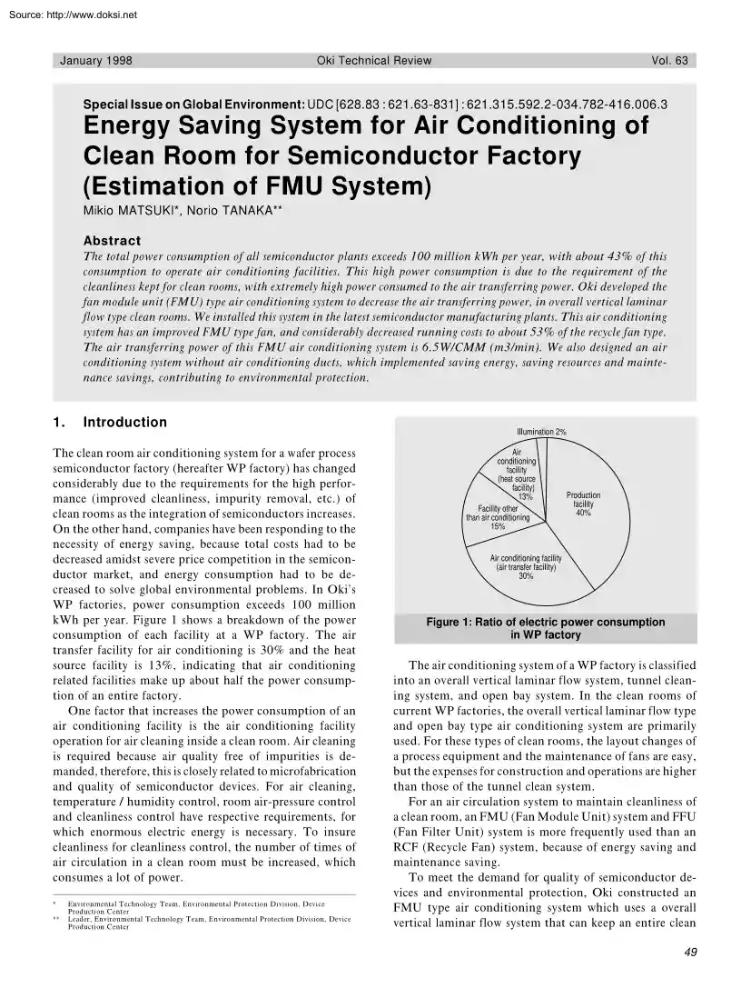
fan type. The air transferring power of this FMU air conditioning system is 6.5W/CMM (m3/min) We also designed an air conditioning system without air conditioning ducts, which implemented saving energy, saving resources and maintenance savings, contributing to environmental protection. 1. Introduction The clean room air conditioning system for a wafer process semiconductor factory (hereafter WP factory) has changed considerably due to the requirements for the high performance (improved cleanliness, impurity removal, etc.) of clean rooms as the integration of semiconductors increases. On the other hand, companies have been responding to the necessity of energy saving, because total costs had to be decreased amidst severe price competition in the semiconductor market, and energy consumption had to be decreased to solve global environmental problems. In Oki’s WP factories, power consumption exceeds 100 million kWh per year. Figure 1 shows a breakdown of the power consumption of each
facility at a WP factory. The air transfer facility for air conditioning is 30% and the heat source facility is 13%, indicating that air conditioning related facilities make up about half the power consumption of an entire factory. One factor that increases the power consumption of an air conditioning facility is the air conditioning facility operation for air cleaning inside a clean room. Air cleaning is required because air quality free of impurities is demanded, therefore, this is closely related to microfabrication and quality of semiconductor devices. For air cleaning, temperature / humidity control, room air-pressure control and cleanliness control have respective requirements, for which enormous electric energy is necessary. To insure cleanliness for cleanliness control, the number of times of air circulation in a clean room must be increased, which consumes a lot of power. * * Environmental Technology Team, Environmental Protection Division, Device Production Center Leader,
Environmental Technology Team, Environmental Protection Division, Device Production Center Illumination 2% Air conditioning facility (heat source facility) 13% Facility other than air conditioning 15% Production facility 40% Air conditioning facility (air transfer facility) 30% Figure 1: Ratio of electric power consumption in WP factory The air conditioning system of a WP factory is classified into an overall vertical laminar flow system, tunnel cleaning system, and open bay system. In the clean rooms of current WP factories, the overall vertical laminar flow type and open bay type air conditioning system are primarily used. For these types of clean rooms, the layout changes of a process equipment and the maintenance of fans are easy, but the expenses for construction and operations are higher than those of the tunnel clean system. For an air circulation system to maintain cleanliness of a clean room, an FMU (Fan Module Unit) system and FFU (Fan Filter Unit) system is more
frequently used than an RCF (Recycle Fan) system, because of energy saving and maintenance saving. To meet the demand for quality of semiconductor devices and environmental protection, Oki constructed an FMU type air conditioning system which uses a overall vertical laminar flow system that can keep an entire clean 49 Source: http://www.doksinet Energy Saving System for Air Conditioning of Clean Room for Semiconductor Factory (Estimation of FMU System) controlled by the dry coil to remove the heat load inside the clean room, and air is circulated back to the fan (FMU). By designing an electric energy conversion efficiency for FMU and other components on the circulation path in the clean room (by improving efficiency of fan and motor of FMU, and by low pressure loss design of the return chamber), air transferring power of the air conditioning system can be decreased, and an energy saving type air conditioning system can be implemented. Fan chamber FMU Filter Filter chamber Supply
chamber OAC Return chamber Cleanroom Dry coil D 2.2 Comparison of air circulation systems Overall vertical laminar flow type air circulation systems used in the clean rooms of WP factories are classified into three types: FMU, RCF and FFU systems. Figure 3 shows a schematic of the air circulation of each system. The features of each system are described below 1. FMU system An FMU system is an air circulation system that has a fan on the top of the Ultra Low Penetration Air filter (hereafter ULPA filter). One fan has the capability to supply air for two or more ULPA filters The air circulation transfer system is an air conditioning ductless type, and is integrated into the building. The air circulation transfer speed is slow to decrease pressure loss. The supply chamber is separated into a fan chamber and filter chamber, which makes the maintenance of fans and filters easier. This system has the smallest air transferring power of all air conditioning circulation systems. 2. RCF
system A RCF system is generally called a “central system”. The air circulation system is mainly an air conditioning duct type. For this system design and construction are easy, but a large fan is required and the high pressure fan must be necessary because the pressure loss of the circulation system is high. The running cost, therefore, becomes high. D C C Figure 2: Air circulation flow in clean room by FMU system room area at high cleanliness, and has no air conditioning ducts, which decreases air transferring power 40% or more. This paper describes an FMU type air conditioning system, and compares its performance with other air circulation systems. Also the installation of an FMU system at the latest WP factory is evaluated, and future expansion plans are described. 2. Selection of air conditioning system 2.1 Overview of air conditioning systems In order to maintain class 1 cleanliness in the air conditioning systems of clean rooms of WP factories, 200~500 times air
circulation is necessary in clean rooms. Figure 2 shows an air circulation flow in a clean room when an FMU type air conditioning system is used. First, air pressurized by a fan (FMU in this case) inside the fan chamber is filtered by the filters inside the filter chamber. The filtered air flows from the filters on the ceiling of the clean room to the clean room as vertical laminar flow, and enters the return chamber. In the return chamber, the temperature of the air is FMU system RCF system Silencer FMU Supply chamber FFU system Duct Fan chamber FMU Supply chamber Filter chamber Supply chamber Fan Corridor Corridor Corridor Return chamber Return chamber Return chamber Dry coil Cleanroom Clean room Clean room Dry coil Silencer Dry coil Figure 3: Schematic diagram of air circulation systems 50 Source: http://www.doksinet January 1998 Oki Technical Review 3. FFU system Just like the FMU system, the FFU system has a fan on top of the filter. In this system, one
fan is used for one filter, so fan and filter are integrated into one unit. This makes the number of fans 5~10 times more than the FMU system, and insuring cleanliness is difficult when system operation trouble occurs. The air circulation transfer system is an air conditioning ductless type, and the running cost is equivalent to the FMU system. 2.3 Evaluation of FMU system Table 1 shows a comparison of the performance of air circulation systems in an overall vertical laminar flow type clean room, and the features and qualitative results of performance are described below. 1. Performance Concerning vibration transmitted to a building, the FMU system, which has a smaller fan and less excitation than the RCF system, does not need vibration isolation measures. For the FMU and FFU systems, it is easy to adjust cleanliness and to install the air circulation system in stages when layout is changed. Air volume can be easily changed for the FMU system by controlling the number of FMUs because
pressure is controlled to be uniform in the filter chamber. For upgrading, the FMU system is relatively easy because the supply chamber is separated into a fan chamber and filter chamber. For maintainability, the FMU system, where one fan supplies air to two or more filters, is also good because even if one fan stops it will have minimal effect on the clean room. In the RCF and FFU systems, however, insuring cleanliness of a clean room is difficult when a fan stops. As a result, the performance of the FMU system is better than the other two systems in terms of vibration, flexibility and maintainability. 2. Cost The initial cost is higher in the sequence of RCF system < FMU system < FFU system in large scale clean rooms. For the running costs, the FMU and FFU system are cheaper than the RCF system because their pressure loss of the air circulation system is 1 / 2 ~ 1 / 4 that of the RCF system. The FMU and FFU systems require more fans than the RCF system but the fans have high
reliability and do not require maintenance. Therefore, FMU and FFU are less expensive than RCF in maintenance as well As a result, for the FMU system, power consumption per unit of air volume can be decreased much more than the other two systems. 3. Delivery FMU and FFU systems can be manufactured at assembly shops by unit house and pre-fabrication. For the RCF system, however, a large crane is necessary to install large fans and ducts. The construction of the RCF system is mostly shop work and there are also Vol. 63 System Item FMU RCF FFU system system system Vibration Layout change Performance Flexibility Air volume change Local cleaning Maintainability Upgrading Maintainability Initial costs Cost Running costs Maintenance costs Energy saving support Term of delivery Constructability Safety Problem handling Construction period General evaluation Table 1: Comparison of performance of air circulation systems many restrictions in the construction periods, for example
ducts in the ceiling must be completed before constructing the clean room ceiling. For the FMU system, the construction period is longer than the FFU system because the supply chamber has a double structure, but construction is easy compared to the RCF system, and shortening the construction period is possible. 4. Safety Comparing safety when fan operation trouble occurs, the influence of trouble on cleanliness of clean rooms is the least (safest) in the FMU system because pressure is is controlled to be uniform in the filter chamber. For the RCF system, the influence of fan operation trouble on clean rooms is large because the air volume of one fan is high. For the FFU system, where one fan is used for one filter, the air flow blown from a filter stops when the fan stops. This causes turbulent flow, a drop in cleanliness, and other negative influences. For the safety in the fan operation trouble period, the FMU system, which hardly affects cleanliness keep in clean rooms, is safer
than the other two systems. From the above (1) ~ (4) performances, we judged that the FMU system is the most effective energy saving type air circulation system to implement targets. 3. Evaluation of FMU system by actual installation at factory We installed an FMU type air conditioning system at Oki’s latest WP factory. The result is as follows When the FMU system was first installed in the research and development building, the air transferring power reduction was only 3.2W/CMM(m 3 /min) The air circulation system at that time had low pressure loss, but efficient 51 Source: http://www.doksinet Energy Saving System for Air Conditioning of Clean Room for Semiconductor Factory (Estimation of FMU System) System RCF system FFU system Item Air volume (CMM) 92 1620 15 External static pressure 22 40 10 Fan Performance Overall efficiency 50 Fan efficiency Motor efficiency (0.58 3 067) 53 Fan efficiency Motor efficiency (0.76 3 070) 21 Fan efficiency Motor efficiency
(0.34 3 061) Power consumption of fan (kW/unit) 0.661 20.0 0.117 Transferring power (W/CMM) 7.2 12.3 7.8 CMM: m3/min, W/CMM: power (W; watt) to transfer 1m3 of air per minute Overall efficiency: electric energy conversion efficiency External static pressure: blast pressure on filter surface Table 2: Comparison of experiment result for air circulation systems fans for that circulation system were not available, which is why a dramatic energy saving effect was not implemented. To further decrease the air transferring power, we reviewed the design values, and experimented with the most efficient FMU type air conditioning system. Table 2 shows the experiment results for the air circulation system. In the experiment, the air transferring power of the FMU system was 7.2W/CMM, and we confirmed that it is possible to develop FMU fans close to experiment values. As a result, we installed an FMU system with improved fans as the air conditioning system at the latest WP factory. Table 3
shows a comparison of initial costs and running costs of air conditioning circulation systems. For the FMU system with improved fans, the air transferring power is 6.5W/CMM, which is a 53% decrease compared with the 52 System FMU system Item FMU system (improved type) RCF system FFU system Initial costs ratio 1.04 1.00 1.17 Running costs ratio 0.47 1.00 0.91 Transferring power (W/CMM) 6.5 13.9 12.6 Table 3: Comparison of initial and running costs of air circulation systems air transferring power of the RCF system. In terms of air transferring power in a 2000m 2 clean room, the FMU system with improved fans can reduce 230kW of power consumption compared with the RCF system. 4. Conclusion We installed an FMU system with improved fans in the latest WP factory as an air conditioning system for overall vertical laminar flow type clean rooms, and implemented dramatic energy savings, resource savings and maintenance savings. The initial cost of this air condition
system was about 4% more than that of the RCF system. The air transferring power of this system was about 53% less than that of the RCF system, which led to considerable reduction of operations costs. In the future, we will install FMU type air conditioning systems as a standard, and will expand this system to all WP factories. For this, further energy savings must be implemented by studying the optimum air volume, optimum sectional area, the shape of air ducts and other matters, and by developing high efficient motors and fans. 5. References 1. Norio Tanaka. “Clean Room,” Electronics materials, December, Supplemental Issue, (1995): 122~123
 Módszertani útmutatónkból megtudod, hogyan lehet profi szakdolgozatot készíteni. Foglalkozunk a diplomamunka céljaival, a témaválasztás nehézségeivel, illetve a forrásanyagok kutatásával, szakszerű felhasználásával is. Szót ejtünk a szakdolgozat ideális nyelvezetéről és struktúrájáról és a gyakran elkövetett hibákra is kitérünk.