A doksi online olvasásához kérlek jelentkezz be!
A doksi online olvasásához kérlek jelentkezz be!
Nincs még értékelés. Legyél Te az első!
Legnépszerűbb doksik ebben a kategóriában


Tartalmi kivonat
DEPARTMENT OF THE NAVY (DON) 19.2 Small Business Innovation Research (SBIR) Proposal Submission Instructions IMPORTANT DON provides notice that Other Transaction Agreements (OTAs) may be used for Phase II awards. Discretionary Technical Assistance (DTA) is renamed Discretionary Technical and Business Assistance (TABA) for the SBIR 19.2 BAA The optional Supporting Documents Volume (Volume 5) is available for the SBIR 19.2 BAA cycle. The optional Supporting Documents Volume is provided for small businesses to submit additional documentation to support the Technical Volume (Volume 2) and the Cost Volume (Volume 3). Volume 5 is available for use when submitting Phase I and Phase II proposals DON will not be using any of the information in Volume 5 during the evaluation. A Phase I Template is provided to assist small businesses to generate a Phase I Technical Volume (Volume 2). INTRODUCTION Responsibility for the implementation, administration, and management of the
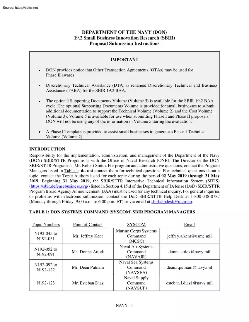
Department of the Navy (DON) SBIR/STTR Programs is with the Office of Naval Research (ONR). The Director of the DON SBIR/STTR Programs is Mr. Robert Smith For program and administrative questions, contact the Program Managers listed in Table 1; do not contact them for technical questions. For technical questions about a topic, contact the Topic Authors listed for each topic during the period 02 May 2019 through 31 May 2019. Beginning 31 May 2019, the SBIR/STTR Interactive Technical Information System (SITIS) (https://sbir.defensebusinessorg/) listed in Section 415d of the Department of Defense (DoD) SBIR/STTR Program Broad Agency Announcement (BAA) must be used for any technical inquiry. For general inquiries or problems with electronic submission, contact the DoD SBIR/STTR Help Desk at 1-800-348-0787 (Monday through Friday, 9:00 a.m to 6:00 pm ET) or via email at sbirhelpdesk@ugroup TABLE 1: DON SYSTEMS COMMAND (SYSCOM) SBIR PROGRAM MANAGERS Topic Numbers Point of Contact N192-045
to N192-051 Mr. Jeffrey Kent N192-052 to N192-091 Ms. Donna Attick N192-092 to N192-122 Mr. Dean Putnam N192-123 Mr. Esteban Diaz SYSCOM Marine Corps Systems Command (MCSC) Naval Air Systems Command (NAVAIR) Naval Sea Systems Command (NAVSEA) Naval Supply Command (NAVSUP) NAVY - 1 Email jeffrey.akent@usmcmil donna.attick@navymil dean.rputnam@navymil esteban.ldiaz1@navymil N192-124 to N192-134 Ms. Lore-Anne Ponirakis Office of Naval Research (ONR) loreanne.ponirakis@navymil N192-135 to N192-137 Mr. Mark Hrbacek Strategic Systems Programs (SSP) mark.hrbacek@sspnavymil The DON SBIR/STTR Programs are mission-oriented programs that integrate the needs and requirements of the DON’s Fleet through research and development (R&D) topics that have dual-use potential, but primarily address the needs of the DON. Firms are encouraged to address the manufacturing needs of the defense sector in their proposals. More information on the programs can be found on the DON
SBIR/STTR website at www.navysbircom Additional information pertaining to the DON’s mission can be obtained from the DON website at www.navymil PHASE I GUIDELINES Follow the instructions in the DoD SBIR/STTR Program BAA at https://sbir.defensebusinessorg/ for requirements and proposal submission guidelines. Please keep in mind that Phase I must address the feasibility of a solution to the topic. It is highly recommended that proposers follow the new DoD Phase I Proposal Template located on the Submission Web site (https://sbir.defensebusinessorg/) as a guide for structuring proposals. Inclusion of cost estimates for travel to the sponsoring SYSCOM’s facility for one day of meetings is recommended for all proposals. PHASE I PROPOSAL SUBMISSION REQUIREMENTS The following MUST BE MET or the proposal will be deemed noncompliant and will be REJECTED. Technical Volume (Volume 2). Technical Volume (Volume 2) must meet the following requirements: o Not to exceed 20 pages, regardless
of page content o Single column format, single-spaced typed lines o Standard 8 ½” x 11” paper o Page margins one-inch on all sides. A header and footer may be included in the one-inch margin. o No font size smaller than 10-point* o Include, within the 20-page limit of Volume 2, an Option that furthers the effort in preparation for Phase II and will bridge the funding gap between the end of Phase I and the start of Phase II. Tasks for both the Phase I Base and the Phase I Option must be clearly identified *For headers, footers, and imbedded tables, figures, images, or graphics that include text, a font size of smaller than 10-point is allowable; however, proposers are cautioned that the text may be unreadable by evaluators. Volume 2 is the technical proposal. Additional documents may be submitted to support Volume 2 in accordance with the instructions for Supporting Documents Volume (Volume 5) as detailed below. Phase I Options are typically exercised upon selection for Phase II.
Option tasks should be those tasks that would enable rapid transition from the Phase I feasibility effort into the Phase II prototype effort. NAVY - 2 Cost Volume (Volume 3). The Phase I Base amount must not exceed $140,000 and the Phase I Option amount must not exceed $100,000. Costs for the Base and Option must be separated and clearly identified on the Proposal Cover Sheet (Volume 1) and in Volume 3. Period of Performance. The Phase I Base Period of Performance must not exceed six (6) months and the Phase I Option Period of Performance must not exceed six (6) months. Supporting Documents Volume (Volume 5). DoD has implemented a Supporting Documents Volume (Volume 5). The optional Volume 5 is provided for small businesses to submit additional documentation to support the Technical Volume (Volume 2) and the Cost Volume (Volume 3). Volume 5 is available for use when submitting Phase I and Phase II proposals. DON will not be using any of the information in Volume 5
during the evaluation. Volume 5 must only be used for the following documents: o Letters of Support o Additional Cost Information - The “Explanatory Material” field in the online DoD Cost Volume (Volume 3) is to be used to provide sufficient detail for subcontractor, material, travel costs, and Discretionary Technical and Business Assistance (TABA), if proposed. If additional space is needed these items may be included within Volume 5. o Funding Agreement Certification o Technical Data Rights (Assertions) - If required, must be provided in the table format required by DFARS 252.227-7013(e)(3) and be included within Volume 5 o Lifecycle Certification o Allocation of Rights NOTE: The inclusion of documents or information other than that listed above (e.g, resumes, test data, technical reports, publications) may result in the proposal being deemed “Non-compliant” and REJECTED. A font size of smaller than 10-point is allowable for documents in Volume 5; however, proposers are
cautioned that the text may be unreadable. Fraud, Waste and Abuse Training Certification (Volume 6). DoD has implemented the optional Fraud, Waste and Abuse Training Certification (Volume 6). DON does not require evidence of Fraud, Waste and Abuse Training at the time of proposal submission. Therefore, DON will not require proposers to use Volume 6. DON SBIR PHASE I PROPOSAL SUBMISSION CHECKLIST Subcontractor, Material, and Travel Cost Detail. In the Cost Volume (Volume 3), proposers must provide sufficient detail for subcontractor, material and travel costs. Enter this information in the “Explanatory Material” field in the online DoD Volume 3. Subcontractor costs must be detailed to the same level as the prime contractor. Material costs must include a listing of items and cost per item. Travel costs must include the purpose of the trip, number of trips, location, length of trip, and number of personnel. When a proposal is selected for award, be prepared to submit
further documentation to the SYSCOM Contracting Officer to substantiate costs (e.g, an explanation of cost estimates for equipment, materials, and consultants or subcontractors). Performance Benchmarks. Proposers must meet the two benchmark requirements for progress toward Commercialization as determined by the Small Business Administration (SBA) on June 1 each year. Please note that the DON applies performance benchmarks at time of proposal submission, not at time of contract award. NAVY - 3 Discretionary Technical and Business Assistance (TABA). If TABA is proposed, the information required to support TABA (as specified in the TABA section below) must be added in the “Explanatory Material” field of the online DoD Volume 3. If the supporting information exceeds the character limits of the Explanatory Material field of Volume 3, this information must be included in Volume 5 as “Additional Cost Information” as noted above. Failure to add the required information
in the online DoD Volume 3 and, if necessary, Volume 5 will result in the denial of TABA. TABA may be proposed in the Base and/or Option periods, but the total value may not exceed $6,500 in Phase I. DISCRETIONARY TECHNICAL AND BUSINESS ASSISTANCE (TABA) The SBIR Policy Directive section 9(b) allows the DON to provide TABA (formerly referred to as DTA) to its awardees to assist in minimizing the technical risks associated with SBIR projects, developing and commercializing products and processes resulting from such projects, and intellectual property protections. Firms may request, in their Phase I Cost Volume (Volume 3) and Phase II Cost Volume, to contract these services themselves through one or more TABA provider in an amount not to exceed the values specified below. This amount is in addition to the award amount for the Phase I or Phase II project Approval of direct funding for TABA will be evaluated by the DON SBIR/STTR Program Office. A detailed request for TABA must include:
TABA provider (firm name) TABA provider point of contact, email address, and phone number An explanation of why the TABA provider is uniquely qualified to provide the service Tasks the TABA provider will perform Total TABA provider cost, number of hours, and labor rates (average/blended rate is acceptable) TABA must NOT: Be subject to any profit or fee by the SBIR applicant Propose a TABA provider that is the SBIR applicant Propose a TABA provider that is an affiliate of the SBIR applicant Propose a TABA provider that is an investor of the SBIR applicant Propose a TABA provider that is a subcontractor or consultant of the requesting firm otherwise required as part of the paid portion of the research effort (e.g, research partner, consultant, tester, or administrative service provider) TABA must be included in the Cost Volume (Volume 3) as follows: Phase I: The value of the TABA request must be included on the TABA line in the online DoD
Volume 3 and, if necessary, Volume 5 as described above. The detailed request for TABA (as specified above) must be included in the “Explanatory Material” field of the online DoD Volume 3 and be specifically identified as “Discretionary Technical and Business Assistance”. Phase II: The value of the TABA request must be included on the TABA line in the DON Phase II Cost Volume (provided by the DON SYSCOM). The detailed request for TABA (as specified above) must be included as a note in the Phase II Cost Volume and be specifically identified as “Discretionary Technical and Business Assistance”. TABA may be proposed in the Base and/or Option periods. Proposed values for TABA must NOT exceed: Phase I: A total of $6,500 Phase II: A total of $5,000 per 12-month period of performance, not to exceed $10,000 per Phase II contract NAVY - 4 NOTE: The Small Business Administration (SBA) is currently developing regulations governing TABA. All regulatory guidance
produced by SBA will apply to any SBIR contracts where TABA is utilized. If a proposer requests and is awarded TABA in a Phase II contract, the proposer will be eliminated from participating in the DON SBIR/STTR Transition Program (STP), the DON Forum for SBIR/STTR Transition (FST), and any other assistance the DON provides directly to awardees. All Phase II awardees not receiving funds for TABA in their awards must attend a one-day DON STP meeting during the first or second year of the Phase II contract. This meeting is typically held in the spring/summer in the Washington, D.C area STP information can be obtained at: https://navystpcom Phase II awardees will be contacted separately regarding this program. It is recommended that Phase II cost estimates include travel to Washington, D.C for this event EVALUATION AND SELECTION The DON will evaluate and select Phase I and Phase II proposals using the evaluation criteria in Sections 6.0 and 80 of the DoD SBIR/STTR Program BAA
respectively, with technical merit being most important, followed by qualifications of key personnel and commercialization potential of equal importance. As noted in the sections of the aforementioned Announcement on proposal submission requirements, proposals exceeding the total costs established for the Base and/or any Options as specified by the sponsoring DON SYSCOM will be rejected without evaluation or consideration for award. Due to limited funding, the DON reserves the right to limit awards under any topic. Approximately one week after the Phase I BAA closing, e-mail notifications that proposals have been received and processed for evaluation will be sent. Consequently, the e-mail address on the proposal Cover Sheet must be correct. Requests for a debrief must be made within 15 calendar days of select/non-select notification via email as specified in the select/non-select notification. Please note debriefs are typically provided in writing via email to the Corporate Official
identified in the firm proposal within 60 days of receipt of the request. Requests for oral debriefs may not be accommodated. If contact information for the Corporate Official has changed since proposal submission, a notice of the change on company letterhead signed by the Corporate Official must accompany the debrief request. Protests of Phase I and II selections and awards must be directed to the cognizant Contracting Officer for the DON Topic Number, or filed with the Government Accountability Office (GAO). Contact information for Contracting Officers may be obtained from the DON SYSCOM Program Managers listed in Table 1. If the protest is to be filed with the GAO, please refer to instructions provided in section 4.11 of the DoD SBIR/STTR Program BAA. CONTRACT DELIVERABLES Contract deliverables for Phase I are typically progress reports and final reports. Required contract deliverables must be uploaded to https://www.navysbirprogramcom/navydeliverables/ AWARD AND FUNDING LIMITATIONS
Awards. The DON typically awards a Firm Fixed Price (FFP) contract or a small purchase agreement for Phase I. In addition to the negotiated contract award types listed in Section 414b of the DoD SBIR/STTR Program BAA for Phase II awards, the DON may (under appropriate circumstances) propose the use of an Other Transaction Agreement (OTA) as specified in 10 U.SC 2371/10 USC 2371b and related implementing policies and regulations. NAVY - 5 Funding Limitations. In accordance with SBIR Policy Directive section 4(b)(5), there is a limit of one sequential Phase II award per firm per topic. Additionally, to adjust for inflation DON has raised Phase I and Phase II award amounts, excluding TABA. The maximum Phase I proposal/award amount including all options (less TABA) is $240,000. The Phase I Base amount must not exceed $140,000 and the Phase I Option amount must not exceed $100,000. The maximum Phase II proposal/award amount including all options (less TABA) is $1,600,000 (unless
non-SBIR/STTR funding is being added). Individual SYSCOMs may award amounts, including Base and all Options, of less than $1,600,000 based on available funding. The structure of the Phase II proposal/award, including maximum amounts as well as breakdown between Base and Option amounts will be provided to all Phase I awardees either in their Phase I award or in a minimum of 30 days prior to the due date for submission of their Initial Phase II proposal. PAYMENTS The DON makes three payments from the start of the Phase I Base period, and from the start of the Phase I Option period, if exercised. Payment amounts represent a set percentage of the Base or Option value as follows: Days From Start of Base Award or Option 60 Days 120 Days 180 Days Payment Amount 50% of Total Base or Option 35% of Total Base or Option 15% of Total Base or Option TOPIC AWARD BY OTHER THAN THE SPONSORING AGENCY Due to specific limitations on the amount of funding and number of awards that may be awarded to a
particular firm per topic using SBIR/STTR program funds (see above), Head of Agency Determinations are now required (for all awards related to topics issued in or after the SBIR 13.1/STTR 13A solicitations) before a different agency may make an award using another agency’s topic. This limitation does not apply to Phase III funding. Please contact the original sponsoring agency before submitting a Phase II proposal to an agency other than the one that sponsored the original topic. (For DON awardees, this includes other DON SYSCOMs.) TRANSFER BETWEEN SBIR AND STTR PROGRAMS Section 4(b)(1)(i) of the SBIR Policy Directive provides that, at the agency’s discretion, projects awarded a Phase I under a BAA for SBIR may transition in Phase II to STTR and vice versa. A firm wishing to transfer from one program to another must contact its designated technical monitor to discuss the reasons for the request and the agency’s ability to support the request. The transition may be proposed prior
to award or during the performance of the Phase II effort. No transfers will be authorized prior to or during the Phase I award. Agency disapproval of a request to change programs will not be grounds for granting relief from any contractual performance requirement(s) including but not limited to the percentage of effort required to be performed by the small business and the research institution (if applicable). All approved transitions between programs must be noted in the Phase II award or an award modification signed by the Contracting Officer that indicates the removal or addition of the research institution and the revised percentage of work requirements. ADDITIONAL NOTES Human Subjects, Animal Testing, and Recombinant DNA. Due to the short timeframe associated with Phase I of the SBIR/STTR process, the DON does not recommend the submission of Phase I proposals that require the use of Human Subjects, Animal Testing, or Recombinant DNA. For example, the ability to obtain
Institutional Review Board (IRB) approval for proposals that involve human subjects can take 6-12 months, and that lengthy process can be at odds with the Phase I goal for time-to-award. Before the DON makes any award that involves an IRB or similar approval requirement, the proposer must demonstrate NAVY - 6 compliance with relevant regulatory approval requirements that pertain to proposals involving human, animal, or recombinant DNA protocols. It will not impact the DON’s evaluation, but requiring IRB approval may delay the start time of the Phase I award and if approvals are not obtained within two months of notification of selection, the decision to award may be terminated. If the use of human, animal, and recombinant DNA is included under a Phase I or Phase II proposal, please carefully review the requirements at: http://www.onrnavymil/About-ONR/compliance-protections/Research-Protections/Human-SubjectResearchaspx This webpage provides guidance and lists approvals that may
be required before contract/work can begin. Government Furnished Equipment (GFE). Due to the typical lengthy time for approval to obtain GFE, it is recommended that GFE is not proposed as part of the Phase I proposal. If GFE is proposed and it is determined during the proposal evaluation process to be unavailable, proposed GFE may be considered a weakness in the proposal. International Traffic in Arms Regulation (ITAR). For topics indicating ITAR restrictions or the potential for classified work, limitations are generally placed on disclosure of information involving topics of a classified nature or those involving export control restrictions, which may curtail or preclude the involvement of universities and certain non-profit institutions beyond the basic research level. Small businesses must structure their proposals to clearly identify the work that will be performed that is of a basic research nature and how it can be segregated from work that falls under the classification and
export control restrictions. As a result, information must also be provided on how efforts can be performed in later phases if the university/research institution is the source of critical knowledge, effort, or infrastructure (facilities and equipment). PHASE II GUIDELINES All Phase I awardees can submit an Initial Phase II proposal for evaluation and selection. The Phase I Final Report, Initial Phase II Proposal, and Transition Outbrief (as applicable) will be used to evaluate the offeror’s potential to progress to a workable prototype in Phase II and transition technology to Phase III. Details on the due date, content, and submission requirements of the Initial Phase II Proposal will be provided by the awarding SYSCOM either in the Phase I contract or by subsequent notification. NOTE: All SBIR/STTR Phase II awards made on topics from solicitations prior to FY13 will be conducted in accordance with the procedures specified in those solicitations (for all DON topics, this means by
invitation only). The DON typically awards a Cost Plus Fixed Fee contract for Phase II; but, may consider other types of agreement vehicles. Phase II awards can be structured in a way that allows for increased funding levels based on the project’s transition potential. To accelerate the transition of SBIR/STTR-funded technologies to Phase III, especially those that lead to Programs of Record and fielded systems, the Commercialization Readiness Program was authorized and created as part of section 5122 of the National Defense Authorization Act of Fiscal Year 2012. The statute set-aside is 1% of the available SBIR/STTR funding to be used for administrative support to accelerate transition of SBIR/STTR-developed technologies and provide non-financial resources for the firms (e.g, the DON STP) PHASE III GUIDELINES A Phase III SBIR/STTR award is any work that derives from, extends, or completes effort(s) performed under prior SBIR/STTR funding agreements, but is funded by sources other
than the SBIR/STTR programs. Thus, a Phase III award is any contract, grant, or agreement where the technology is the same as, derived from, or evolved from a Phase I or a Phase II SBIR/STTR award and given to the firm that received the Phase I/II award. This covers any contract, grant, or agreement issued as a follow-on Phase III award or NAVY - 7 any contract, grant, or agreement award issued as a result of a competitive process where the awardee was an SBIR/STTR firm that developed the technology as a result of a Phase I or Phase II award. The DON will give Phase III status to any award that falls within the above-mentioned description, which includes assigning SBIR/STTR Technical Data Rights to any noncommercial technical data and/or noncommercial computer software delivered in Phase III that was developed under SBIR/STTR Phase I/II effort(s). Government prime contractors and/or their subcontractors must follow the same guidelines as above and ensure that companies operating
on behalf of the DON protect the rights of the SBIR/STTR firm. NAVY - 8 NAVY SBIR 19.2 Topic Index N192-045 N192-046 N192-047 N192-048 N192-049 N192-050 N192-051 N192-052 N192-053 N192-054 N192-055 N192-056 N192-057 N192-058 N192-059 N192-060 N192-061 N192-062 N192-063 N192-064 N192-065 N192-066 N192-067 N192-068 N192-069 N192-070 N192-071 N192-072 N192-073 N192-074 N192-075 N192-076 N192-077 N192-078 N192-079 N192-080 N192-081 N192-082 N192-083 N192-084 N192-085 N192-086 N192-087 Active Explosive Ordnance Disposal Bomb Suit Cooling System Vest (AEODSUV) Lightweight Road Wheel (LwRW) Mobile Recycling Facility – Expeditionary (MRF-X) Automatic Track Generation Micro Preprocessor for Dismounted Electronic Warfare Family of Foreign Object Damage Mitigation Equipment (F2ME) Virtual Reality for Ground Vehicle Survivability, Lethality, and Vulnerability Wargaming Event Design, Scenario Development, and Execution Software Suite for Modeling and Simulation (M&S) Tool Automation
Advanced Aircraft Electrical Load Management System Quantum Cascade Lasers Manufacturing 10X Cost Reduction Lowering the Probability of an Adversary Recognizing Inverse Synthetic Aperture Dwells While Maintaining Vessel Classification Capabilities Long-Wave Infrared (IR) Window/Dome Life-Cycle Cost (LCC) Reduction Holographic Optical Element for Free Space Optical Communication System on Mobile Platforms Advanced Alternative Gun Lubricant Predictor of Aircraft Structural Loads Due to Buffet Submarine Mast Discrimination Techniques for High-Altitude Maritime Surveillance Radar Multi-Sensor Sonobuoy Innovative Millimeter Wave Positioning System for Collision/Obstacle/Brown-Out with Sense and Avoidance Autonomous Unmanned Aerial Vehicle (UAV) Flight Without Supervisory Control High Dynamic Range Real-Time LIDAR Digitizer and Processor Real-Time Mapping from Over-Water Imagery Artificially Intelligent Object with Virtual Presentation of Engineering and Logistics Data Non-Invasive Radio
Frequency System Characterization Anti-reflective Surface for Infrared Optical Fiber Endfaces Tool for Analysis to Predict Strength and Durability of Curved and Tapered Composite Structures under Multiaxial Loading [Navy has removed topic N192-069 from the 19.2 SBIR BAA] Manned-Unmanned Directional Mesh Enhanced Tactical Airborne Networks Innovative Methods for Correlating Physiological Measures of Pilot Workload to Handling Qualities Nondestructive Characterization of Microstructure and Grain Orientation on Large, Complex Parts Versatile Emitters Flow Forming Bomb Bodies Secure Communications Link Between Robotics and Autonomous Systems Fiber Optic Pressure Sensing for Military Aircraft (MIL-Aero) Environments Apparatus for Characterizing Mixed Failure Modes in Cross Deck Pendants Network Retention During Jamming Mission Unmanned Airborne Reconfigurable Naval Communications Network Open Architecture Development Environment for Radar Mode Design Improved Data Tracking System for
Crew-Served Weapon Systems Mobile Phased Array Antenna for Robotic Autonomous Systems (RAS) Using Optical Broadband Communications Non-Traditional Airborne Anti-Submarine Warfare (ASW) System Room Temperature Shelf-Life Pre-Impregnated Carbon Fiber Fabric for use in Out-ofAutoclave Aircraft Repair Rapid Repair of Corroded Fastener Holes Advanced Signal Analysis Techniques for Use on Non-Periodic Radio Frequency Signals Headset Equivalent of Advanced Display Systems (HEADS) NAVY - 9 N192-088 N192-089 N192-090 N192-091 N192-092 N192-093 N192-094 N192-095 N192-096 N192-097 N192-098 N192-099 N192-100 N192-101 N192-102 N192-103 N192-104 N192-105 N192-106 N192-107 N192-108 N192-109 N192-110 N192-111 N192-112 N192-113 N192-114 N192-115 N192-116 N192-117 N192-118 N192-119 N192-120 N192-121 N192-122 N192-123 N192-124 N192-125 N192-126 N192-127 N192-128 N192-129 N192-130 N192-131 N192-132 N192-133 N192-134 Collision Avoidance System for Operations in Dense Airspace Environment Inverse
Synthetic Aperture Radar (ISAR) Imaging in the Presence of Electronic Attack (EA) Modern Forward Error Correction (FEC) and Automatic Repeat Request (ARQ) Algorithms for Tactical Data Links Line-of-Sight (LOS) Low Probability of Detection/Intercept (LPD/LPI) Millimeter Wave Communication Distributed Sensing of Unsteady Surface Pressure Fields Threat Prioritization Decision Aid for Theater Anti-Submarine Warfare (TASW) Multiplayer Serious Game for Anti-Submarine Warfare Sonar Operator Training Multi-Instruction Set Architecture (ISA) Processing with a Peripheral Component Interconnect express (PCIe) Oxygen Delivery and Monitoring System Advanced Video Compression Capability Non-Explosive Wire Rope and Cable Cutter 3D Visualization Capability for Fleet Remotely Operated Vehicles (ROVs) Passive Cooling for Aircraft Carrier Jet Blast Deflectors (JBD) Unmanned Vehicle Launch & Recovery (L&R) for MK VI Patrol Boats Blind Mating Connection for 19-inch Electronic Industries Alliance
Racks in AEGIS Computing Infrastructure Field Serviceable Non-Acoustic Data Logging Sensor Module for Towed Arrays Large Instantaneous Bandwidth High Dynamic Range Digitizer FireFly™ Based Network Switch Innovative Helicopter Hangar Door Seals Quiet Launch for 6-Inch Externally Stowed Devices Structurally Integrated Enclosure for AEGIS Combat System Computer Hardware Undersea Sensor Network Performance Modeling and Cost Tool [Navy has removed topic N192-110 from the 19.2 SBIR BAA] Metal Additive Manufacturing of Pressure Vessel Experimental Models [Navy has removed topic N192-112 from the 19.2 SBIR BAA] Combat System Dynamic Resource Management Improved Propulsion Technologies for Mine Countermeasures Unmanned Undersea Vehicle Systems Durable Foreign Object Debris (FOD) Screens for Air Cushion Vehicles Deep Submergence Tactical Acoustic Doppler Current Profiler (ADCP) and Doppler Velocity Logger (DVL) Undersea Acoustic Risk Analysis Decision Aid for Theater Anti-Submarine Warfare
(TASW) Mission Planning Application Level Cybersecurity Threat Detection Autonomous Collective Protection System (CPS) Small-Scale Velocity Turbulence Sensors for Undersea Platforms Torpedo Advanced Processor Build (APB) Algorithm Development Spatially Integrating Magnetometer Food Waste Transfer System from Ship Galleys to the Ship Solid Waste Processing Equipment Digital Twin Technology for Naval Maintenance Training and Operations High Current Cooled Flexible Bus Work Systems Metamaterial Devices for Photonic Systems High Heat Flux Thermal Management Technologies for Aluminum Decks Innovative Artificial Intelligence Features to Reduce Signal Dropout due to Clipping, Channel Fading, and Multi-path Interference Early Detection of Information Campaigns by Adversarial State and Non-State Actors Formable Reactive Metal Composites with Tailorable Energy Release Properties AI-Based Trend and Sentiment Analytics for Latent-Risk Discovery Accelerating Knowledge Acquisition for Close Combat
Warriors Advanced Non-Electrochemical Energy Storage Modernizing Maintenance Operations and Training NAVY - 10 N192-135 N192-136 N192-137 Autonomous Flight Termination for Use in Submarine-Launched Missile Applications Remote Analog-to-Digital Translator for Use in Submarine-Launched Missile Applications Propulsion Monitoring for Use in Missile Space Applications NAVY - 11 NAVY SBIR 19.2 Topic Descriptions N192-045 TITLE: Active Explosive Ordnance Disposal Bomb Suit Cooling System Vest (AEODSUV) TECHNOLOGY AREA(S): Materials/Processes ACQUISITION PROGRAM: PfM LCES, PM Engineer Systems (ES) OBJECTIVE: Develop a lightweight micro cooling system that integrates with the latest generation of liquid cooling and dehumidification vest garments and is resilient enough to withstand heavy abrasive use under the EOD Bomb Suit (9) while providing unrestrictive movement during EOD operations. DESCRIPTION: The EOD Bomb Suit (9) provides the EOD technician protection from fragmentation,
blast pressure, heat and light flash, and flame generated by Unexploded Ordnance (UXO) and Electrically Initiated Devices (EID) when conducting Render Safe Procedures (RSP) or disruption procedures on ordnance and/or devices that cannot be attacked remotely [Ref 2]. The bomb suit provides a wide field of vision, flexibility, and mobility and can weigh in excess of 125 lbs. A Self-Contained Breathing Apparatus (SCBA), which provides breathable air regardless of the ambient atmosphere, and an EOD helmet are also worn which add an additional 60 lbs. The time EOD personnel have for conducting disarming procedures can be limited simply by the total weight of their Personnel Protective Equipment (PPE) and lack of adequate cooling. Failure to complete a mission can be catastrophic. Current cooling techniques involve packing ice into a web-like vest and using gravity to allow melted water to go down the upper torso. This SBIR topic seeks innovative approaches for a lightweight micro cooling
system that integrates with the latest generation of liquid cooling and dehumidification vest garments [Ref 3]. The cooling system shall weigh no more than 10 lbs. (5 lbs objective) and be self-powered up to 6 hrs An ability to attach to auxiliary/supplemental power is also desired. The cooling system shall be able to limit EOD personnel exposure conditions within the bomb suit to 80°F, 50% relative humidity and not drop below 65°F, 10% relative humidity during the 6-hour self-powered timeframe. At a minimum, cooling shall be focused on the torso and core cooling Target design goals for the system shall be to operate in all climates and environments that may be encountered by Marines such as arctic, desert, jungle, and coastal, and shall not operationally degrade when ambient temperatures are between 125°F and -25°F. The system shall also fully operate in all humidity levels up to 100 percent and must be resistant to the effects of salt/water spray and extreme sand and dust
conditions to the extent outlined in MIL-STD-810G [Ref 1]. The cooling system materials shall be structurally resilient to withstand heavy abrasive use under the EOD Bomb Suit (9) [Refs 2, 3]. PHASE I: Develop concepts for an EOD Bomb Suit micro cooling system that meets the requirements highlighted in the Description above. Demonstrate the feasibility of the concepts in meeting Marine Corps needs and establish that the concepts can be developed into a useful product for the Marine Corps. Establish feasibility by material testing and analytical modeling, as appropriate. Provide a Phase II development plan with performance goals, key technical milestones, and a technical risk reduction strategy. PHASE II: Develop a scaled prototype evaluation to determine its capability in meeting the performance goals defined in the Phase II development plan and the Marine Corps requirements for the EOD Bomb Suit micro cooling system [Ref 4]. Demonstrate system performance through prototype evaluation
and modeling or analytical methods over the required range of parameters including 150 deployment cycles. Use the evaluation results to refine the prototype into an initial design that will meet Marine Corps requirements. Prepare a Phase III development plan to transition the technology to Marine Corps use. PHASE III DUAL USE APPLICATIONS: Support the Marine Corps in transitioning the technology for Marine Corps use. Develop a plan to determine its effectiveness in an operationally relevant environment Support the Marine Corps for test and validation to certify and qualify the system for Marine Corps use. NAVY - 12 The potential for commercial application and dual use is high. Beyond the Marine Corps and DoD applications, there are federal civilian agencies, law enforcement agencies, firefighting agencies, and emergency responders that can use this type of personal cooling system. Recreational and athletic applications are also a possibility REFERENCES: 1. Mil-Std-810G, Department
of Defense Test Method Standard: Environmental Engineering Considerations and Laboratory Tests; http://www.everyspeccom/mil-std/mil-std-0800-0899/mil-std-810g 12306/ 2. EOD 9 Suit & Helmet; https://wwwmedengcom/Products/PersonalProtectiveEquipment/MedEngEODIEDD/EOD9SuitHelmetaspx 3. Public Safety Bomb Suit Standard, NIJ Standard-011700; https://www.googlecom/url?sa=t&rct=j&q=&esrc=s&source=web&cd=13&cad=rja&uact=8&ved=2ahUKEwibjo WO3PfAhU1CjQIHbFaAhkQFjAMegQIBRAC&url=https%3A%2F%2Fwww.ncjrsgov%2Fpdffiles1%2Fnij%2F227357 .pdf&usg=AOvVaw3e6J9iwd6KNLLRPyVJXuuc 4. 2010 ANTHROPOMETRIC SURVEY OF US MARINE CORPS PERSONNEL: METHODS AND SUMMARY STATISTICS; https://apps.dticmil/docs/citations/ADA581918 KEYWORDS: EOD Bomb Suit; Micro Cooling System; Personal Cooling; Refrigeration; Explosive Ordnance Disposal TPOC-1: Phone: Email: Robert Davies 703-432-5952 robert.wdavies1@usmcmil TPOC-2: Phone: Email: David Keeler 703-432-5771 david.keeler@usmcmil
Questions may also be submitted through DOD SBIR/STTR SITIS website. N192-046 TITLE: Lightweight Road Wheel (LwRW) TECHNOLOGY AREA(S): Ground/Sea Vehicles ACQUISITION PROGRAM: Marine Corps Assault Amphibious Vehicle Family of Vehicles (AAV-FoV) The technology within this topic is restricted under the International Traffic in Arms Regulation (ITAR), 22 CFR Parts 120-130, which controls the export and import of defense-related material and services, including export of sensitive technical data, or the Export Administration Regulation (EAR), 15 CFR Parts 730-774, which controls dual use items. Offerors must disclose any proposed use of foreign nationals (FNs), their country(ies) of origin, the type of visa or work permit possessed, and the statement of work (SOW) tasks intended for accomplishment by the FN(s) in accordance with section 3.5 of the Announcement Offerors are advised foreign nationals proposed to perform on this topic may be restricted due to the technical data under US
Export Control Laws. OBJECTIVE: Develop lightweight road wheel technologies, for marine and on/off road complex mission profiles, that use innovative materials, design, and manufacturing processes; reduce scheduling, manpower, and time constraints; and achieve increased cost efficiencies to translate into lifecycle cost reductions. NAVY - 13 DESCRIPTION: Currently, the Assault Amphibious Vehicle-Family of Vehicles (AAV-FoV) platforms (AAVP7A1 personnel variant, AAVC7A1 command and control variant, and AAVR7A1 recovery variant) share the same road wheel component as the U.S Army Bradley Fighting Vehicle (BFV) (#12358464) The road wheels are made of forged steel integrated with rubber that incur a substantial weight penalty of 2,011 pounds (24 wheels) per vehicle. The Marine Corps seeks the development of a new road wheel, made of strong yet lightweight materials with either abrasion resistance coating or innovative lightweight steel wear plate designed to sustain track center
guide’s abrasion impact without track derail concern. This lightweight wheel design should be able to reduce fuel consumption and prolong the rubber tire life, while increasing interval time between maintenance operations. This topic seeks to explore innovative and alternative road wheel system designs for military vehicles. Of particular interest are concepts that satisfy the following criteria: • Reduce road wheel weight by >40% (BFV steel road wheel - 83.8 lbs/pc) • Reduce or eliminate galvanized corrosion concern • Decrease lifecycle cost • Increase time interval between maintenance • Improve maintainability efficiency • Decrease fuel consumption • Improve rubber tire life with min. average life of 2000 miles under AAV-FoV configuration The lightweight road wheel systems shall operate in basic water, and on primary and secondary roads, trails, and cross-country conditions. Basic water conditions are of salt and fresh, open ocean, surf zones, lakes, rivers,
streams, marshes, swamps, snow, slush, and ice. Primary roads are high quality paved, secondary pavement, and rough pavement surfaces. Secondary Roads are loose surface, loose surface with washboard and potholes, and Belgian block surfaces. Trails are one-lane, unimproved, seldom-maintained, loose surface roads intended for low-density traffic. Typically trails have no defined road width, large obstacles (rubble, boulder, logs, and stumps), cross ditches, washouts, steep slopes, and no bridging/culverts. Cross-country terrain can consist of tank trails with crushed rock or having large exposed obstacles (rocks, boulders, etc.), but there are no roads, routes, well-worn trails, or man-made improvements. This includes but is not limited to flat desert, marshes, vegetated plains, jungle, dense forest, mountains, and urban rubble. The system shall be operable and maintain Full Operational Capability (FOC) under the operational conditions as follows: • Tracked platform with six stations
per side * Roadwheel size: OD 24 inches • Road wheel impact load cases: 3.5g [vertical], 2g [vertical] @ rim edge, 3g [lateral], and combined (25g [lateral] + 1.5g [vertical]) 1g = 8000 lbf (nominal vertical load) • Road wheel fatigue load cases: 1g @ rim edge with a minimum 1.55M cycles life; Combined (1.2g[vertical]+25g[lateral]) with a minimum 155M cycles life • Lateral slopes of up to 40% capable of sine wave operation • Ascending / descending grades of up to 60% • Trails grades up through 40% • Maintain 64.37 kph (40 mph) forward speed on level Primary Roads • Accelerate in the forward direction from 0 to 20 mph (32.2 kph) in 105 seconds or less on a dry, hard, level surface • Stop within 15.24 meters (50 feet) from the forward speed of 322 kph (20 mph) on a dry, hard, level surface with a drift not to exceed 0.91 meters (3 feet) in the actual stopping distance • Capable of 360 degrees pivot steering turn within 45 seconds or less • Discrete obstacle
negotiation, including vertical step (36”), gap (8’), and trench crossing • Sustain riverine operation • Ascend a 91 cm (36 inch) vertical obstacle in the forward and backward directions without preparation vehicle • Ambient air temperatures from -51º C (-60º F) to +52º C (125.6º F) PHASE I: Develop wheel concepts to reduce weight and to improve the service life of road wheel system by exploring the use of alternative materials, design, maintainability, and manufacturing techniques that meet the requirements outlined in the Description. Develop test methodology for operations in marine environments and rubber tire durability that evaluate the expected life of lightweight road wheel systems. Demonstrate the feasibility NAVY - 14 of the concept in meeting the Marine Corps requirements. Establish the wheel design feasibility by material sample testing and analytical modeling to deliver the promised performance and capability, as appropriate. Provide a Phase II plan that
identifies the verification approach of performance goals, key technical milestones, and addresses technical risks. PHASE II: Develop prototypes and a process for testing. Evaluate the prototype to determine if the performance goals defined in the Phase II development plan and the requirements have been met. Demonstrate system performance through full-scale field testing to include durability and environmental performance. Use results to refine the design to optimize the performance. Prepare a Phase III plan to transition the technology to the Marine Corps. PHASE III DUAL USE APPLICATIONS: Complete full-scale application, testing, demonstration, implementation, and commercialization. The Marine Corps could buy future lightweight road wheel system through a Phase III contract if the performer has the manufacturing capacity. The Marine Corps could also use the results of this effort to update standards in future competitive contracts that would facilitate a teaming arrangement with a
company that could produce the quantities required for future acquisitions and sustainment. The technologies developed under this SBIR effort would have direct application to other Department of Defense applications including other services’ lightweight road wheel systems on Tactical Vehicles, Heavy Equipment, and Industrial Equipment. The technologies developed under this SBIR topic would be of interest to industrial, agricultural, and recreational vehicles. The technologies would also have applications for large bulldozers, excavators, graders, and farming equipment used in mining, construction and farming industries. REFERENCES: 1. AMCP 706-356, AMC Pamphlet: Engineering Design Handbook – Automotive Series – Automotive Suspensions. US Army Materiel Command: April 1967 2. Wong, Jo Yung “Theory of Ground Vehicles, 4th Edition” New York: A Wiley-Interscience Publication, 2008 KEYWORDS: Tanks; Rubber Compounds; Cold Spray Coating; Composite Materials; Reinforcement Rings; Wear
Plate; Induction Hardening; Stress Releasing; Coatings; Sprays; Armored Personal Carrier APC; Aluminum; Solid Rubber Wheel; Amphibious; Fuel Savings; Combat Vehicle; Heavy Weight; Component Durability; Reduced Life Cycle Cost TPOC-1: Phone: Email: Joe Chou 703-784-1312 chunchuan.chou@usmcmil TPOC-2: Phone: Email: Jeff Banko 703-784-1665 jeffrey.banko@usmcmil Questions may also be submitted through DOD SBIR/STTR SITIS website. N192-047 TITLE: Mobile Recycling Facility – Expeditionary (MRF-X) TECHNOLOGY AREA(S): Materials/Processes ACQUISITION PROGRAM: Expeditionary Fabrication Laboratory (EXFAB) NAVY - 15 OBJECTIVE: Develop a mobile recycling facility capable of cleaning, drying, and processing thermoplastics into pellets and filament for use in material extrusion equipment such as 3-D printers and injection molders in remote and austere environments. All equipment must fit within an intermodal container (conex) DESCRIPTION: Logistics are the fundamental consideration in
forward deployment, consuming one-third of the Department of Defense’s budget [Ref 1]. The former Commandant of the Marine Corps said that the US supply lines in Afghanistan “represent an operational vulnerability” and “we are getting hit; we are losing Marines.” Although resupply can take in excess of 45 days, and a 600-warfighter forward operating base (FOB) requires 22 convoy trucks per day to supply the base, the majority of supplies are brought in rather than sourced locally [Ref 1]. Even a small reduction in the amount of supplies that need to be shipped in could greatly impact the warfighter’s safety and logistical costs. In addition, a significant amount of waste/scrap materials is generated on a daily basis on military operating bases. Plastics represent nearly 8% of the total waste, averaging approximately 450 lbs/Marine/yr [Ref 2]. These materials are either recycled or burned in open pit fires, inflicting damage to the environment and personnel health. Additive
manufacturing (AM) technologies are critical to maintaining operational readiness of the military by reducing the logistical supply chain dependence and allowing point-of-need manufacturing. Recent research has demonstrated the feasibility of turning plastic waste into 3-D printing feedstock in the laboratory [Ref 3]. Developing such methods to process waste into useful AM feedstocks in-field is expected to have a great impact on many parts of the Marine Corps, as well as other units in remote locations in which re-use of materials could present significant cost and energy savings. More automation of the process is critical to reduce the man-hours and training required. Currently there exists no such land-based automated recycling system (ARS) to reclaim waste plastics and failed 3-D prints into pellets and/or filament for AM or injection molding processes. NASA, together with Tethers Unlimited, have created the Refabricator for recycling select plastics in space [Ref 5]. Limitations
of this technology include limited plastic types (Ultem and Acrylonitrile Butadiene Styrene (ABS) only) and low output. In addition, the system is not commercially available. A mobile plastic recycling extrusion laboratory does not exist This topic seeks the development of an Expeditionary Mobile Recycling Facility (MRF-X) that provides the capability of processing thermoplastics into pellets and filament for use in material extrusion equipment such as 3-D printers and injection molders in remote and austere environments. The MRF-X shall have all equipment housed in a standard or expandable 20-foot ISO container, with proper tie-downs and capable of meeting MIL-STD 810F/G necessary for transport by land and sea. The unit shall contain duct work to support a 60,000 BTU Environmental Control Unit (ECU) and meet OSHA standards of temperature range of 68-76 °F and humidity range of 20-60%. In addition, the power is limited to the power available on a forward operating base, approximately
180 KW for a typical 500-warfighter FOB [Ref 1]. The unit shall have plastic sorting, cleaning, drying and shredding capabilities Automation of all or part of these capabilities is preferred. In addition, the unit shall have an ARS capable of processing a wide range of thermoplastics from consumer-grade packaging such as polyethylene terephthalate (PET), polypropylene, polyethylene, polystyrene as well as from failed 3-D prints made of materials such as ABS, PLA, Ultem, and Polyether ether ketone (PEEK). The ARS shall melt and reconstitute thermoplastics into 175 ± 01 and/or 2.85 ± 01 mm diameter filament spools or pellets at an output rate exceeding 2 kg per hour Filament shall have sufficient flexibility to enable spooling and be free of defects such as particulate debris and air/moisture bubbles. The ARS until should be able to melt plastics with melting temperatures up to 400 °C Mechanical testing (tensile) should be performed to verify that performance of reconstituted plastics
is within expected range based on literature values for polymer type. PHASE I: Develop concepts for a mobile plastic recycling facility that meets the requirements described above. Demonstrate the feasibility of the concepts in meeting Marine Corps needs and establish that the concepts can be developed into a useful product for the Marine Corps. Establish feasibility by material testing and analytical modeling, as appropriate. Provide a Phase II development plan with performance goals and key technical milestones, and that will address technical risk reduction. PHASE II: Develop a scaled prototype evaluation. Evaluate the prototype to determine its capability in meeting the performance goals defined in the Phase II development plan and the Marine Corps requirements for the mobile plastic recycling facility. Demonstrate system performance through prototype evaluation and modeling or analytical methods over the required range of parameters including numerous deployment cycles. Use
evaluation results to NAVY - 16 refine the prototype into an initial design that will meet Marine Corps requirements. Prepare a Phase III development plan to transition the technology to Marine Corps use. PHASE III DUAL USE APPLICATIONS: Support the Marine Corps in transitioning the technology for Marine Corps use. Develop mobile plastic recycling facility for evaluation to determine its effectiveness in an operationally relevant environment. Support the Marine Corps for test and validation to certify and qualify the system for Marine Corps use. Beyond Marine Corps and DoD applications, federal and international humanitarian aid agencies can use this recycling facility to aid in disaster relief, fabricating essential items at the point-of-need. Local communities, particularly in remote or underdeveloped areas, could use this technology to reduce waste and 3-D print parts to improve their livelihoods and quality of life. Schools and academia could also employ the recycling facility
to develop an in-house recycling program to make feedstock to support 3-D printing laboratories. REFERENCES: 1. “Strategic Environmental Research and Development Program (SERDP) Sustainable Forward Operating Bases” Noblis, 5/21/10, pp.9, 16 https://wwwserdp-estcporg/content/download/8524/104509/file/FOB Report Publicpdf 2. Cosper, SD, Anderson, HG, Kinnevan, K, and Kim, BJ “Contingency Base Camp Solid Waste Generation” ERDC/CERL TR-13-17, (2013). https://appsdticmil/dtic/tr/fulltext/u2/a613823pdf 3. Zander, NE, Gillan, MG, and Lambeth, RH “Recycled polyethylene terephthalate as a new FFF feedstock material.” Additive Manufacturing, Volume 21, May 2018, pp 174–182 https://www.sciencedirectcom/science/article/pii/S2214860418300046?via%3Dihub 4. Kreiger, M A, Mulder, M L, Glover, A G, and Pearce, J M “Life Cycle Analysis of Distributed Recycling of Post-Consumer High Density Polyethylene for 3-D Printing Filament.” Journal of Cleaner Production, Volume 70, 2014, pp.
90-96 https://digitalcommonsmtuedu/cgi/viewcontentcgi?article=1035&context=materials fp 5. Tethers Unlimited “Refabricator: A Recycling and Manufacturing System for the International Space Station” http://www.tetherscom/Refabricatorhtml KEYWORDS: Ex-Fab; Filament; Polymer; Additive Manufacturing; 3-D printing; Plastic Recycling; Expeditionary; Mobile Laboratory; Pellets; Acrylonitrile Butadiene Styrene; ABS; Ultem TPOC-1: Phone: Email: Nicole Zander 410-306-1695 nicole.ezanderciv@mailmil TPOC-2: Phone: Email: Anthony Molnar 703-432-5925 anthony.molnar@usmcmil TPOC-3: Phone: Email: David Keeler 703-432-5771 david.keeler@usmcmil Questions may also be submitted through DOD SBIR/STTR SITIS website. N192-048 TITLE: Automatic Track Generation Micro Preprocessor for Dismounted Electronic Warfare NAVY - 17 TECHNOLOGY AREA(S): Battlespace, Electronics, Sensors ACQUISITION PROGRAM: Modi II & Multi-Function EW (MFEW); Marine Air-Ground Task Force (MAGTF) EW Ground Family
of Systems The technology within this topic is restricted under the International Traffic in Arms Regulation (ITAR), 22 CFR Parts 120-130, which controls the export and import of defense-related material and services, including export of sensitive technical data, or the Export Administration Regulation (EAR), 15 CFR Parts 730-774, which controls dual use items. Offerors must disclose any proposed use of foreign nationals (FNs), their country(ies) of origin, the type of visa or work permit possessed, and the statement of work (SOW) tasks intended for accomplishment by the FN(s) in accordance with section 3.5 of the Announcement Offerors are advised foreign nationals proposed to perform on this topic may be restricted due to the technical data under US Export Control Laws. OBJECTIVE: Develop an innovative and operationally suitable solution for Electronic Warfare Systems (EWS) Programs of Record (PORs) data pre-processing at the tactical edge that, enabled by artificial intelligence (AI)
and machine learning (ML) algorithms, must be able to process vast amounts of raw data to detect, track and recommend actions on signals of interest in a complex electromagnetic environment. DESCRIPTION: Marine Corps Systems Command (MCSC) provides dismounted EWS for geo-locating, direction finding and countering threats on the ground and in the air. Currently these systems collect vast amounts of raw and unfiltered data that describe signals from electromagnetic sources in the form of individual pulse descriptor words (PDW) – potentially billions per minute. The raw data is then transmitted back to the tactical operations center (TOC) where it is downloaded, processed and analyzed to identify objects and track targets of interest. The sheer amount of raw data being transmitted over limited bandwidth and post-processed at the TOC is not conducive to real-time signal of interest tracking and hinders the Marines’ ability to react to potential threats. The advent of advanced AI and ML
techniques, such as Long Short-Term Memory (LSTM) networks, and the availability of opensource software tools (e.g, TensorFlow) and off-the-shelf processing capabilities (eg, NVIDIA) provides opportunity to more efficiently and effectively process electromagnetic signal data by enabling preprocessing and filtering at the antennae sensor. The ability to detect composite tracks in real time at the tactical edge will reduce the amount of data necessarily transmitted and post-processed at the TOC, resulting in more efficient signal analysis and ultimately improved effectiveness of EWS capabilities. MCSC is seeking a preprocessing solution for dismounted EWS systems. The solution will utilize innovative AI/ML algorithms to process large amounts of raw data (i.e, PDW) and recommend high priority tracks of interest indicative of patterns of life. The AI/ML algorithms will support signal classification to identify benign versus adversary signals based on a signals of interest list. In an
operational scenario, a dismounted EWS could collect up to billions of PDW per minute, resulting in potentially millions of tracks. Processing the collected PDW from the electromagnetic environment is complicated by radio frequency (RF) reflections, clutter (e.g, foliage, structures, terrain, birds), and the sheer volume of PDW. The envisioned pre-processing capability should be able to process the PDW in such a way that objects, particularly slow moving or intermittent signals, can be automatically filtered from clutter and identified as a high priority for further analysis. Requirements for the preprocessing solution are as follows: Demonstrate a preprocessing capability to: (1) track very slow moving objects (0-40mph); (2) track objects among slow (0-40mph) moving point clutter (e.g, birds and insects); and (3) identify and rejoin intermittent or disjointed tracks in a highly complex electromagnetic environment. Each capability listed above should be demonstrated with a
representative test case commensurate with the volume and complexity of data likely encountered in the battlespace. The solution must have sufficient time difference of arrival (TDOA) granularity to be able to draw out multiple tracks at once from billions of data points. The system shall have a Signal of Interest (SOI) false alarm rate no greater than 5% (Threshold) and no greater than 2% (Objective) within any 24-hour period of time. The hardware, software, or combined hardware/software solution must be easily integrated with a dismounted backpack-sized EWS, such as the current MODI II, and be antenna agnostic. A representative standard gain antenna should be used for demonstration purposes The system shall be no larger than 12” by 6” by 4” (not including an antenna) and weighing no more than 5 lbs. not including the battery (Threshold) and no more than 5 lbs. including the battery (Objective) The preprocessor messaging shall be Joint Interface Control Document (JICD) 4.2
compliant The solution should utilize commercial off-the-shelf hardware NAVY - 18 and software to the maximum extent possible. Proposals must describe the envisioned processing solution to include the software, hardware or combined approach. The proposer should also indicate expected size, weight, false alarm rate, classification performance, and memory requirements. Software or firmware shall meet cybersecurity requirements. The Phase I effort will not require access to classified information. If need be, data of the same level of complexity as secured data will be provided to support Phase I work. Work produced in Phase II may become classified Note: The prospective contractor(s) must be U.S Owned and Operated with no Foreign Influence as defined by DOD 5220.22-M, National Industrial Security Program Operating Manual, unless acceptable mitigating procedures can and have been implemented and approved by the Defense Security Service (DSS). The selected contractor and/or
subcontractor must be able to acquire and maintain a secret level facility and Personnel Security Clearances, in order to perform on advanced phases of this contract as set forth by DSS and the Marine Corps in order to gain access to classified information pertaining to the national defense of the United States and its allies; this will be an inherent requirement. The selected company will be required to safeguard classified material IAW DoD 522022-M during the advance phases of this contract. PHASE I: Develop concepts for an automatic track generation that can be integrated with dismounted EWS, such as the MODI II [Ref 5], and that meets the requirements described above. Demonstrate the feasibility of the concepts in meeting Marine Corps needs through modeling and simulation. Establish that the concepts can be developed into a useful product for the Marine Corps. Provide a Phase II development plan with performance goals and key technical milestones, and that will address technical
risk reduction. This Phase II plan will include specification for a prototype. PHASE II: Develop a scaled prototype integrated with a standard gain antenna for evaluating purposes and with data inputs representative of dismounted EWS PDW volume and complexity. Evaluate the prototype to determine its capability in meeting the performance goals defined in the Phase II development plan and the Marine Corps requirements for automatic track generation preprocessing. Demonstrate system performance through prototype evaluation and modeling or analytical methods that demonstrate the preprocessing capability with a test case for each of the three demonstration requirements listed in the Description. Use evaluation results to refine the prototype into an initial design that will meet Marine Corps requirements. Prepare a Phase III development plan to transition the technology to Marine Corps use. It is probable that the work under this effort will be classified under Phase II (see Description
section for details). PHASE III DUAL USE APPLICATIONS: Support the Marine Corps in transitioning the technology for Marine Corps use, including testing and validation to certify and qualify the system. Develop a ruggedized automatic track generation pre-processor for integration and evaluation to determine its effectiveness in an operationally relevant environment. AI- and ML-enabled processing has potential use in a variety of commercial applications, including speech and handwriting recognition, communications, stock market predictions, robotics and autonomy. Other Government agencies with the need to identify and track objects or trends in complex environments, such as the Federal Aviation Administration, Federal Communications Commission, Customs and Border Protection, and the Federal Bureau of Investigation, could adapt this technology for insights and efficiencies to their particular missions. REFERENCES: 1. Gers, Felix, Schmidhuber, Jürgen & Cummins, Fred “Learning to
Forget: Continual Prediction with LSTM Neural computation.” Neural Computation, October 2000, 12(10)2451-71 101162/089976600300 2. Greff, K, Srivastava, R, Koutnik, J, Steunebrink, B and Schmidhuber, J “LSTM: A Search Space Odyssey” IEEE Transactions on Neural Networks and Learning Systems, 2016. https://arxivorg/abs/150304069 3. 2018 US Marine Corps Science & Technology Strategic Plan https://wwwonrnavymil/-/media/Files/AboutONR/2018-USMC-S-and-T-Strategic- NAVY - 19 Plan.ashx?la=en&hash=73B2574A13A8EC6AAE60CF4670E05C6F97309B8F 4. Electronic Warfare Marine Corps Reference Publication 3-32D1, United States Marine Corps Publication Control Number144 000246 00. 02 May 2016 https://bookpdf.services/downloads/marine corps reference publication mcrp 3 32d 1 formerly mcwp 3 40 5 electronic warfare 2 may 2016.pdf 5. “Counter Radio-Controlled Improvised Explosive Device (RCIED) Electronic Warfare (CREW)” United States Marine Corps, 12 July 2018. The Official Website of
the United States Marine Corps http://www.candpmarinesmil/Programs/Focus-Area-4-Modernization-Technology/Part-7-Force-Protection/CREW/ KEYWORDS: Electronic Warfare; Electromagnetic Spectrum; Signal Processing; Machine Learning; Artificial Intelligence; Neural Network; Recurrent Neural Network; Long Short-term Memory; Composite Tracker; Pulse Descriptor Word; NVIDIA; TensorFlow TPOC-1: Phone: Email: Alicia Owsiak 703-432-2765 alicia.owsiak@usmcmil TPOC-2: Phone: Email: Bradford Crane 703-432-2847 bradford.crane@usmcmil Questions may also be submitted through DOD SBIR/STTR SITIS website. N192-049 TITLE: Family of Foreign Object Damage Mitigation Equipment (F2ME) TECHNOLOGY AREA(S): Ground/Sea Vehicles ACQUISITION PROGRAM: Family of Foreign Object Damage Mitigation Equipment Acquisition Program OBJECTIVE: Develop a family of foreign object damage (FOD) mitigation equipment (F2ME) that increases the ability of aircraft to operate in austere environments, reduce engine repair cost,
and enhance aircraft sortie rates through FOD prevention. DESCRIPTION: The Marine Corps requires a debris mitigation system capable of removing or relocating foreign objects from aircraft operating surfaces at main air bases, air facilities, and Forward Arming and Re-fueling Sites (FARPs) at CONUS and OCONUS locations. The current Marine Corps FOD mitigation capability is not configured properly with adequate equipment to provide the necessary support for all Marine Corps and Joint aircraft platforms in support of the Marine Corps Operating Concept (MOC). Recent analysis outlines growing cost and decreased flight hours/operations due to FOD incidents. The amount of debris and required timelines for removal is disproportionate to our current FOD mitigation equipment capabilities in support of operational concepts and at our expeditionary aircraft training sites, thus reducing the air combat element support forward and their ability to train pilots. This effort should capitalize on new
techniques and procedures that will provide more durable expedient debris removal in a shorter time; Reference 1 is a study that can be used as a reference to characterize foreign object debris that may be found on a runway. The F2ME capability must take advantage of modern developments in debris removal equipment, must be easily deployable, must be flexible enough to work in all geographic locations and environments, and provides the capability to quickly remove debris from concrete, asphalt, and airfield surfacing materials (AM2). The F2ME supports the deployment, employment, sustainment and redeployment of the Marine Corps aviation assets across the full range of military operations. Reference 1 identifies key attributes of an airport foreign object debris management program, as well as equipment considerations. NAVY - 20 The F2ME capability must be able to support USMC and Joint aircraft; operate in extreme cold/hot environments; and be easily transportable, modular,
lightweight, and efficient. The F2ME capability must be able to clear, at a minimum, 7,500 sq ft of aircraft operational area per minute using towable/driven systems (pre-operational) and 1,500 sq ft per minute using man-portable systems (rapid response between sorties). It is envisioned that a F2ME will encompass equipment that will be consumable (towable mats) along with robust equipment (i.e, vehicles, tow hitches, and blowers). Summary of capabilities: • Capable of removing debris on aircraft operational surfaces in support of USMC aircraft and various joint platforms • Operate in expeditionary environments, per MIL-STD 810F/G • Transportable by strategic and tactical, air, land, and sea assets • Containerized for ease of use, scalability, and employment Desired System attributes: (1) Debris Removal Capability. The F2ME shall contain equipment capable of removing debris from an airfield surface without causing damage, to include surfaces consisting of aluminum matting
generation 2 (AM2), at the following rates: - 6,500 square feet per minute (sq ft/min), Threshold (T), 7,500 sq ft/min, Objective (O); - Landing surface with joints, fractures, and/or aircraft tie-down areas at a rate of 3,500 sq ft/min (T), 4,500 sq ft/min (O); - Man-portable configuration on an individual aircraft landing site in a remote location at a rate of 1,500 sq ft/min (T), 2,500 sq ft/min (O); Marines conducting FOD mitigation operations require equipment that can quickly and efficiently remove FOD from landing surfaces of various sizes and locations. (2) Debris Removal Effectiveness. The FOD Mitigation vacuum shall pick up and retain 94% (T=O) by weight of all debris in its path. All vacuum capable F2ME shall be certified to the Environmental Protection Agency air quality standard of Particulate Matter 10 (PM-10) T=O. The FOD Mitigation friction mat shall be capable of collecting 95% (T), 98% (O) of all debris in its path. The FOD Mitigation debris blowers (towed and
man-portable) shall each be capable of relocating 95% (T), 98% (O) of all debris in its path. Consult the Federal Specification for Airfield Runway Sweeping reference 32 for a list of the materials utilized to test the effectiveness of debris collecting equipment [Ref 3]. Marines conducting FOD mitigation operations require equipment that can effectively remove FOD from landing surfaces of various types and conditions. (3) Cleanout. The F2ME vacuum and sweeping components shall be designed to facilitate rapid cleanout of debris by an individual person in less than 5 minutes (T), 3 minutes (O). Rapid cleanout of debris will allow a quicker turnaround of FOD mitigation resources. (4) Battery Power. The F2ME shall utilize direct current battery power for all man-portable, expeditionary components equipped with a motor, with a runtime of at least 30 minutes (T) and 45 minutes (O). The quantity of batteries provided with each component shall be sufficient to provide at least 2 hours of
continued use (T=O). The F2ME shall require no more than 600 Watts to recharge batteries, via 120VAC/220 VAC 50-60 Hz source, of equipment powered by direct current (T=O). Battery powered equipment emits less of an audible signature than equipment powered by internal combustion engine and reduces the burden of maintaining additional fuel in an expeditionary environment. Expected battery life is 3 years (T) or 5 years (O) (5) Fuel Required. The F2ME components that have internal combustion engines shall utilize the current approved diesel fuel (JP8/F24) (T=O). The F2ME shall have fuel tank ports compatible with Marine Corps and NATO NAVY - 21 dispensing nozzles; and shall have fuel ports capable of accepting fuel from a 5-gallon can (T = O). Man-portable platforms may use standard military gasoline. The platforms must be capable of operating on standard military fuel and accepting fuel from standard means. (6) Weather. The F2ME shall be capable of operating in austere environments
and temperatures ranging from -25° Fahrenheit (F) to 120° F (T=O). The F2ME shall be capable of effectively operating in crosswind conditions with wind speeds up to 20 miles per hour (MPH) (T), 30 MPH (O). The F2ME must be capable of operating worldwide in varying environments in order to support the continuum of operations. (7) Transportability. The F2ME shall be capable of being transported by land, air and sea via naval, Maritime Prepositioning Force (MPF) or commercial shipping as defined below This capability and its individual components must be transportable to forward deployed forces to enable expansion of inter-theater and intra-theater lines of communication using Marine Corps transportation assets. • Land: common rail carrier, commercial truck, tactical vehicles (T=O). • Air: C-130, C-17, and C-5 (T=O). Towable and man-portable components of the family of systems (FOS) shall be internally transportable aboard MV-22B and CH 53E (T=O). • Sea: U.S Navy amphibious
assault ships, landing craft utility, MPF, and commercial shipping (T=O) (8) Weight. The F2ME shall not exceed the following weights: • Man-portable: 40 lbs. (T), 20 lbs (O) • Towable: 2,500lbs (T), 25 lbs. (O) • Self-Propelled: 26,500 lbs. GVWR (T), 3,500 lbs GVWR (O) (9) Container. The F2ME Man-portable assets shall be containerized in a Quadruple Container (T=O) (10) Maintainability. The F2ME shall be designed to permit maintenance and repairs by military personnel utilizing general purpose tools with minimum training requirements. Maintenance for the F2ME components will not require special tools (T=O). [Rationale: It is essential for the F2ME to maintain a high state of combat readiness with very few maintenance requirements in order to substantially increase the number and quality of FOD mitigation missions that can be completed successfully.] (11) Tool Storage. The F2ME tools, accessories and mechanics tool kit shall be stored within a self-contained, weather proof,
lockable storage container (T=O). [Rationale: This type of storage for tools and accessories will allow for their protection from the effects of the weather and prevent pilferage.] (12) NATO Slave Receptacle. Self-propelled and towable F2ME components powered by internal combustion engines equipped with electronic starting shall also be equipped with a standard NATO slave receptacle to support maintenance and operations (T=O). [Rationale: Redundancy in electronic starting systems ensures continued operations when replacement batteries may not be readily available.] (13) Operator's Preventive Maintenance Checks and Services. The F2ME shall be designed to allow the operator/crew to conduct Operator's Preventive Maintenance Checks and Services (PMCS) (before, during, and after) in 30 minutes or less (T); 10 minutes (O). [Rationale: Marines must be able to perform Operator's PMCS in a reasonable amount of time to maximize a capability's time spent performing its primary
mission in accordance with policies outlined in Marine Corps Order (MCO) 4790.25] (14) Operator's Night Vision Equipment. The F2ME that is self-propelled shall be compatible with standard Marine Corps issue night vision equipment that will enable a Marine to operate the components during night and in limited visibility (T = O). [Rationale: The F2ME requires the capability to operate at night and during periods of limited visibility.] (15) Family of Systems (FOS) Components. The F2ME may have individual equipment components that employ NAVY - 22 vacuums, blowers, friction mats, and brushes to meet the requirements of removing debris from aircraft landing surfaces (T=O). [Rationale: A FOS will allow for FOD Mitigation that is scalable and able to be performed on various types and sizes of landing surfaces.] (16) Personnel Physical Dimensions. All references to personnel (operator, maintainer, or other) will range from 5th percentile female to 95th percentile male categories (T
= O). [Rationale: The F2ME will be operated and maintained by personnel of various sizes. Note: Sizes of personnel are defined in DOD-HDBK-743A] (17) Condition Based Maintenance. The F2ME should be equipped with current industry standard sensors, electronic components and other technologies to enable Condition Based Maintenance Plus (CBM+) to be conducted through the collection of essential data and analysis of failures to make prognostic maintenance decisions (T = O). [Rationale: The application and integration of appropriate CBM+ processes and capabilities into the F2ME will improve the availability, reliability, and operation of the equipment and reduce support costs across its lifecycle.] (18) Electronic Maintenance Support System. The self-propelled F2ME should be equipped with an interface port for connection to the current Electronic Maintenance Support System (EMSS) with access to Interactive Electronic Technical Manuals (IETM) (T = O). [Rationale: This will enable F2ME
troubleshooting, repair, and component adjustment and allow access to documentation of maintenance actions.] (19) Magnetic Pickups. The F2ME may incorporate the use of a mounted or towed magnet assembly that is height adjustable, self-cleaning, and capable of removing 98% (T), 100% (O) of the ferrous metals in its path at operational speed. [Rationale: Magnets are a relatively simple and effective means for removing ferrous metal debris without damaging vacuum components.] (20) Soil Stabilization. The F2ME may contain equipment capable of mixing soil-stabilizing palliatives to a depth of 8 inches (T), 16 inches (O) at a rate of 50 sq ft/min (T), 100 sq ft/min (O). [Rationale: Dust abatement through soil stabilization is a key component of FOD mitigation for airfield and landing surfaces. Proper mixing of palliatives into the soil prevents creation of additional FOD from surface-laid applications.] (21) Environmental Factors – Operating Climatic Characteristics. The F2ME capability
shall be able to operate in air temperatures from -25F to 120 F without special kits (O=T), per MIL-STD 810F/G. [Rationale: To support the MAGTF for world-wide expeditionary operations.] PHASE I: Develop concepts for F2ME that meets the requirements described above. Demonstrate the feasibility of the concepts in meeting Marine Corps needs by material testing and analytical modeling, as appropriate. Establish that the concepts can be developed into a useful product for the Marine Corps. Provide a Phase II development plan with performance goals and key technical milestones, and addresses technical risk reduction. PHASE II: Develop a scaled prototype evaluation to determine its capability in meeting the performance goals defined in the Phase I development plan and the Marine Corps requirements for the F2ME. Demonstrate system performance through prototype evaluation and modeling or analytical methods over the required range of parameters including numerous deployment cycles. Use
evaluation results to refine the prototype into an initial design that will meet Marine Corps requirements. Prepare a Phase III development plan to transition the technology to Marine Corps use. PHASE III DUAL USE APPLICATIONS: Support the Marine Corps in transitioning the technology for Marine Corps use. Develop the F2ME for evaluation to determine its effectiveness in an operationally relevant environment Support the Marine Corps for test and validation to certify and qualify the system for Marine Corps use. The development of a family of foreign object mitigation equipment has the potential for use at any airport or air facility where there is a requirement to remove or relocate debris from aircraft operating surfaces. The kit would most likely appeal to smaller airports or auxiliary air fields where limited support or staff is on hand but the need still exists to clear debris from aircraft operating surfaces. NAVY - 23 REFERENCES: 1. Herricks, Edwin, Mayer, David and Majumdar,
Sidney “Foreign Object Debris Characterization at a Large International Airport.” DOT/FAA/TC-TN14/48, February 8, 2015 https://www.airporttechtcfaagov/DesktopModules/EasyDNNNews/DocumentDownloadashx?portalid=0&module id=3682&articleid=36&documentid=60 2. O’Donnell, Michael “Airport Foreign Object Debris (FOD) Management” Advisory Circular 150/5210-24, 9/30/2010. http://wwwfaagov/documentLibrary/media/Advisory Circular/AC 150 5210-24pdf 3. OO-S-2796, FEDERAL SPECIFICATION, SWEEPER, VACUUM OR REGENERATIVE, AIRFIELD RUNWAY, SELF-PROPELLED, DED. 22 FEB 1993 http://everyspeccom/FED SPECS/O/OO-S-2796 7912/ KEYWORDS: Foreign Object Damage; FOD; Family of Foreign Object Damage Mitigation Equipment; F2ME; Debris Removal; Expeditionary; Airfield Surfacing Materials; AM2; Aircraft Surfaces TPOC-1: Phone: Email: Dan Presley 843-228-8332 daniel.spresley@usmcmil TPOC-2: Phone: Email: Michael Farley 703-432-5922 michael.jfarley@usmcmil Questions may also be submitted through
DOD SBIR/STTR SITIS website. N192-050 TITLE: Virtual Reality for Ground Vehicle Survivability, Lethality, and Vulnerability TECHNOLOGY AREA(S): Ground/Sea Vehicles ACQUISITION PROGRAM: Armored Reconnaissance Vehicle, PdM Advanced Combat Vehicle, Assault Amphibious Vehicle Survivability OBJECTIVE: Develop a virtual reality (VR) visualizer for viewing and interacting with computer-aided design (CAD) and modeling and simulation (M&S) results in a 1:1 scale, 3-dimensional environment in order to reduce the cost of the survivability, lethality, and vulnerability design process and improve understanding of the root cause of vehicle survivability performance issues. DESCRIPTION: Virtual reality is currently being used across many industries, including for engineering design and analysis also for training, logistics, medical therapy, and entertainment. However, these current capabilities do not address critical component of Marine Corps ground vehicle design – vehicle survivability,
lethality, and vulnerability. Under this SBIR topic, the small business will develop a VR visualizer for aiding in the survivability, lethality, and vulnerability design, acquisition, and evaluation of military ground vehicles and related systems. The ability to view M&S assets in the VR environment provides the following benefits: • Ease of communicating design information to those in management and decision-making positions • Intuitive control and model manipulation • Full geometric fidelity without resolution limitations (see the smallest component and the entire platform in the same rendering) • Appreciation and understanding of asset scale • Ability to evaluate asset layout and configuration, including human factors considerations without a physical vehicle • True scale and interactivity that provide a useful tool for design evaluation NAVY - 24 • More rapid understanding of design issues and simulation results, such as load paths and debris trajectories
Work produced in Phase II may become classified. Note: The prospective contractor(s) must be US owned and operated with no foreign influence as defined by DoD 5220.22-M, National Industrial Security Program Operating Manual, unless acceptable mitigating procedures can and have been implemented and approved by the Defense Security Service (DSS). The selected contractor and/or subcontractor must be able to acquire and maintain a secret level facility and Personnel Security Clearances, in order to perform on advanced phases of this project as set forth by DSS and Marine Corps Systems Command (MCSC) in order to gain access to classified information pertaining to the national defense of the United States and its allies; this will be an inherent requirement. The selected company will be required to safeguard classified material IAW DoD 5220.22-M during the advanced phases of this contract PHASE I: Develop concepts for a VR visualizer that meet the requirements described below. This includes
developing the workflow and translators to efficiently convert CAD and M&S files into a format compatible with the visualizer engine the awardee selects. Demonstrate the feasibility by showing that the conversion tool works with CAD formats Solidworks or ProE/Creo and one survivability, lethality, or vulnerability-related simulation toolset used by Marine Corps Systems Command or PEO Land Systems (LS-Dyna, Velodyne, MUVES, etc). Further establish feasibility by demonstrating development of the visualizer engine and viewer environment, including the ability to 1) take distance measurements, 2) navigate/manipulate the models, and 3) view quantitative simulation results, such as through colored contours. Provide a Phase II development plan with performance goals and key technical milestones that will address technical risk reduction. The awardee will be assessed on the ability to meet the requirements described above. Phase I efforts will be UNCLASSIFIED, and contractors will not be
given secure access. Researchers will be provided data of the same level of complexity as that for secure data in lieu of secure access if needed to support Phase I work. PHASE II: Expand the number of types of compatible data files for the visualizer, to include compatibility with at least LS-Dyna and Velodyne. Moreover, expand the visualizer’s capability to include the ability to view both static results and animations of dynamic simulations and handle both individual parts as well as full-vehicle models. Ensure that the visualizer includes built-in tools for asset configuration management, such as part number identification, revision numbers, reference drawings/CAD files, and component mass and material information. Include the ability to interactively import and place Government Furnished Equipment (GFE) and developmental design items for fitment and Human Factors Engineering studies. Ensure that the user of the VR visualizer has the ability to embed design review observations
and feedback within the viewer. Deliver a prototype VR visualizer software, along with associated stand-alone hardware and software necessary to view static models and dynamic simulations in virtual reality. Demonstrate the capability for multiple people to interact in the VR environment at the same time. Evaluate the prototype to determine its capability in meeting the performance goals defined in the Phase II development plan and the Marine Corps requirements for the VR system. Demonstrate system performance through prototype evaluation, which must be certified to run simulations classified SECRET and below. Refine the prototype using evaluation results into an initial design that will meet Marine Corps requirements. Prepare a Phase III development plan to transition the technology to Marine Corps use. It is probable that the work under this effort will be classified under Phase II (see Description section for details). PHASE III DUAL USE APPLICATIONS: Support the Marine Corps in
transitioning the technology for Marine Corps use if Phase II is successful and program funding is available. This includes maintaining and expanding the capabilities of the viewer to meet the needs of specific program offices. Develop VR for evaluation to determine its effectiveness in a relevant environment. Support the Marine Corps for test and validation to certify and qualify the system for Marine Corps use. A VR visualizer can be marketed to engineering, entertainment, medical, construction, and architecture fields. REFERENCES: 1. Gobbetti, Enrico and Scateni, Riccardo “Virtual Reality: Past, Present, and Future” CRS4, Center for Advanced Studies, Research and Development in Sardinia, Cagliari, Italy, 27 July 2018. http://wwwcrs4it/vic/data/papers/vr- NAVY - 25 report98.pdf 2. Maleshhov, Stoyan and Chotrov, Dimo “Post-processing of Engineering Analysis Results for Visualization in VR System.” Semantic Scholar, Virtual Reality Lab, Technical University Sofia,
Bulgaria, 27 July 2018 https://pdfs.semanticscholarorg/e1c6/0cf84ad797372cb7dd15bf4267748ec4feaapdf 3. Marks, S, Estevez, JE, and Connor, AM “Towards the Holodeck: Fully Immersive Virtual Reality Visualisation of Scientific and Engineering Data.” Proceedings of the 29th International Conference on Image and Vision Computing New Zealand, 2014. DOI: 101145/26834052683424 4. Vergara, Diego, Rubio, Manuel Pablo, and Lorenzo, Miguel “On the Design of Virtual Reality Learning Environments in Engineering.” MDPI, Multimodal Technologies and Interaction, 27 July 2018 http://www.mdpicom/2414-4088/1/2/11/pdf KEYWORDS: Ground Vehicle; Virtual Reality; Survivability; Lethality; Vulnerability; Modeling & Simulation TPOC-1: Phone: Email: Cynthia Bodner 703-784-3331 cynthia.elandgren@usmcmil TPOC-2: Phone: Email: Patrick Hart 703-784-2036 patrick.ahart@usmcmil Questions may also be submitted through DOD SBIR/STTR SITIS website. N192-051 TITLE: Wargaming Event Design, Scenario
Development, and Execution Software Suite for Modeling and Simulation (M&S) Tool Automation TECHNOLOGY AREA(S): Information Systems ACQUISITION PROGRAM: PMM-180, Wargaming Capability Program Office (PM WGC) OBJECTIVE: Develop a prototype wargame planning, design, scenario development, and execution software suite and browser-based interface for use by professional military and civilian planners executing the wargame event lifecycle execution process. Prototyping effort will focus on techniques and automation that make Modeling and Simulation (M&S) easier to use and more responsive with special emphasis on M&S to visualize game conditions and results/outcomes. DESCRIPTION: One of the most difficult problems associated with Professional Military Wargaming [Ref 1] is to design a wargame that will deliver the output required to meet objectives such as informing a specific acquisition decision or gaining insight into future operating environments [Refs 3,4]. The small planning
staff must develop an appropriate and immersive scenario that provides the necessary context for player actions and decisions. During the wargame lifecycle, the specific wargame objectives can evolve over the course of major planning events. Planners must have technical enablers/tools that allow them to evolve the corresponding game design and scenario responsively and collaboratively with stakeholders. The current Marine Corps Wargaming process lacks these enablers. During wargame execution, dynamic insights require effective visualization of wargame conditions and dynamic (highly automated) outcome adjudication methods. If automated, outcome adjudication can then be visualized to accelerate insights. In order to dynamically exploit these insights during the wargame, it is necessary to conduct NAVY - 26 concurrent excursions. This is best accomplished through the use of synthetic environments and modeling and simulation [Ref 2]. Currently available simulations require weeks and
months of post-event analysis to gain the desired insights, long after the subject matter expert (SME) participants have dispersed. Various currently available commercial products allow an expert user, highly experienced in the particular tool and highly knowledgeable in all applicable warfare areas, to plan, configure, and execute wargames utilizing these tools. This project would expand that capability to individuals experienced in wargame planning, scenario development, and wargame execution to likewise take advantage of these highly capable commercial wargaming simulations in an effective manner and within available time constraints. The current state-of-the-art for all such capabilities is that they require a user who is both a domain and system/software SME to be used effectively and take time to develop products. The intent is to evolve to a state where non system/software experts can use the applications directly to develop the wargame design, conduct live excursions during
execution based on player inputs, and visualize game outcomes dynamically both graphically and analytically, Key Elements and Objectives: • A “TurboTax-like” workflow management interface that guides the planner step by step through the wargame planning and design processes and decision-making • Ability to output wargame schedule, design, and scenario in a set of flexible open electronic formats/reports that can be translated easily into formal documents and other systems • Collaborative wargame planning and design by staff at distributed locations • Ability to generate/initialize the event scenario conditions in the simulation • Development of a mechanism to automate scenario initialization of simulation • Ability to conduct informal “inductive style” runs in simulation prior to wargame execution to generate useful products for wargame participants such as capabilities/constraints of forces and key dynamics of the environment • Ability to use simulation to
visualize the scenario and environment in ways that make the wargame more effective and immersive • Ability to run the simulation during wargame execution as excursions to exploit findings/insights • Development and optimization of synthetic data collection and results visualization software that can present result in a manner inherently meaningful, useful, and intuitive • Ability to modify simulation databases to make use of high-quality authoritative data • Ability to generate and ingest player actions and decision into simulation in an automated and efficient manner • Ability to produce tech replays in simulation for use in event hot washes • Ability to produce data logs from simulation runs for post-game analysis and excursions Specific Tasks that must be executed in the software: Planning Tasks: • Manage user access and accounts • Create, edit, and save a wargame event (project) • Define the Wargame in terms of sponsor requirements, purpose, and objectives •
Scope the Wargame in terms of participants, Command Level, event size, and formality • Develop wargame schedule and timeline • Define participant roles • Design wargame in terms of format and rules Scenario Creation Tasks: • Define Wargame scenario • Define Scenario “Sides” and Force Lists (basic) • Define Scenario starting conditions and timeline • Develop workflows for M&S Scenario Generation including order of battle/force laydown and terrain • Develop an open technical exchange specification for M&S Scenario Generation Wargame Execution Tasks: • Develop workflows and techniques that use M&S to conduct pre-game analysis • Develop data collection and results visualization software that can import and display simulation data/results electronically and filter in various ways • Develop techniques/methods for effective results visualization; for example, as participants develop potential NAVY - 27 Courses of Action (COAs) for the next turn in
the game, the tool intuitively presents visualizations of the COAs under consideration including relevant metrics. • Explore techniques for managing automated results adjudication provided by simulation and how best to utilize during wargame execution • Develop a specification for plans/digital orders and graphics to translate player actions and decisions into simulation behavior • Automate detailed force behavior based on player orders/intent and produce reports • Generate reports of findings PHASE I: Develop a concept for how this software would function and how it would be integrated into the wargaming simulations and tools to be prototyped concurrently with this effort. These prototypes will utilize open architecture standards, common modeling and simulation protocols, and industry best practices to facilitate interoperability of capability sets, to include this effort. Develop software architecture, user interface design, integration approach, and associated artifacts.
Evaluate and document the feasibility of the approach Develop a Phase II plan, including essential performance goals and key technical milestones, keeping the focus on enabling the end user to plan and execute complex wargames utilizing state-of-the-art wargame simulation tools. Evaluate risks inherent in the approach and develop risk reduction and mitigation options. PHASE II: Execute the plan developed in Phase I to develop a scaled prototype for evaluation. Provide demonstrations at key milestones of progress made to date on the tool, and degree of integration thus far obtained. The technical performance parameters developed in Phase I will be evaluated. The desired outcomes from the demonstrations and evaluations include: • Software enhancement of Wargaming design and scenario development • Ability to responsively edit game design and scenario as required • Ability to generate electronic reports/plans for use in formal documents • Collaborative capability that allows
distributed planners to work together on game design and scenario • Intuitive interface that can be rapidly taught to users (e.g, under two days of instruction) • Extent to which simulation can support game and results visualization, as determined by responsiveness of tool to player input (i.e, the degree to which the tool enables game and results visualization without interfering with the progress of the game) • Methods to employ simulation to automate details and adjudicate outcomes • Methods to translate player intent/actions/decisions into actionable digital orders that can be executed and adjudicated in simulation • Ability to automate significant force behavior in simulation based on high level player orders and intent • Required processing power/scalability for multiple game excursions • Technical exchange specifications for M&S • Identification of gaps in M&S capabilities that require work-arounds or specific dedicated development to mitigate PHASE III
DUAL USE APPLICATIONS: Transition the developed technology to Program Manager Wargaming Capability. Further development and demonstration will be focused on operating the software within the lifecycle of a live wargame, from planning and scenario development through execution. Support formal testing and validation with specific simulation tools. Address any integration and performance issues that arise during testing Increasingly businesses are turning to serious gaming to provide strategic insight and inform decision making. Many such businesses wish to garner insights from the voluminous data collected from myriad sources. However, there is a barrier to entry for these businesses in having the resident skill sets required to utilize the highly complex available tools. The technologies developed under this SBIR topic would have potential applicability to any of the industries which have begun to embrace serious gaming and wargaming. For example, industries are turning to cyberwar
gaming to uncover aspects of their attack surface which may have gone previously unnoticed. Similarly, defense contractors use gaming to help gain strategic insight into how to compete in a budget-limited environment with myriads of competitors. REFERENCES: NAVY - 28 1. Curry, John, ed “Peter Perla’s The Art of Wargaming: A Guide for Professionals and Hobbyists” United States Naval Institute, 2012. 2. Gorak, Mark “Introduction to Modeling and Simulation Special Edition: Wargaming” Journal of Cyber Security and Information Systems, Vol. 4, No 3, November 20, 2016 https://wwwcsiacorg/journal-article/introduction-tomodeling-and-simulation-special-edition-wargaming/ 3. Pournelle, Phillip “Designing Wargames for the Analytic Purpose” Phalanx, Vol 50, No 2, June 2017, pp 4853 https://wwwjstororg/stable/26296384?seq=1#page scan tab contents 4. Work, Bob and Selva, Paul “Revitalizing Wargaming is Necessary to be Prepared for Future Wars” War on the Rocks, December 8,
2015. https://warontherockscom/2015/12/revitalizing-wargaming-is-necessary-to-be-preparedfor-future-wars/ KEYWORDS: Wargaming; Modeling and Simulation (M&S); User Experience; Analysis; Game Design, Scenario Development, and Execution; Automation TPOC-1: Phone: Email: Tyson Kackley 703-432-3636 tyson.kackley@usmcmil TPOC-2: Phone: Email: Brian Gregg 757-492-8298 brian.gregg@navymil Questions may also be submitted through DOD SBIR/STTR SITIS website. N192-052 TITLE: Advanced Aircraft Electrical Load Management System TECHNOLOGY AREA(S): Air Platform ACQUISITION PROGRAM: PMA275 V-22 Osprey The technology within this topic is restricted under the International Traffic in Arms Regulation (ITAR), 22 CFR Parts 120-130, which controls the export and import of defense-related material and services, including export of sensitive technical data, or the Export Administration Regulation (EAR), 15 CFR Parts 730-774, which controls dual use items. Offerors must disclose any proposed use of
foreign nationals (FNs), their country(ies) of origin, the type of visa or work permit possessed, and the statement of work (SOW) tasks intended for accomplishment by the FN(s) in accordance with section 3.5 of the Announcement Offerors are advised foreign nationals proposed to perform on this topic may be restricted due to the technical data under US Export Control Laws. OBJECTIVE: Develop innovative concepts for as close to 100% loading of available power source capacity as possible to support growing power demand of added aircraft electrical loads and provide protection to aircraft power distribution wiring. DESCRIPTION: Most aircraft power systems handle power source failures by either limiting total load to the power source capacity remaining with one power source failed, or shedding an entire bus when a power source fails. The problem with the first approach is most of the time the aircraft has excess power capacity that is not being utilized. The problems with the second
approach are the shed bus may include loads that for a particular mission are higher in priority, and it may shed more loads than necessary to avoid overloading the remaining power source. NAVY - 29 It is especially necessary to make the most efficient utilization of the available power source capacity because it is limited; it is very difficult and expensive to increase power source capacity. Besides the power source itself, an increase usually requires increased distribution capacity, increased cooling for the power source, and increased drive system capacity. Space and weight provisions for these may be impossible without a major airframe redesign Aircraft electric power systems need to support increases in connected loads that result from new and expanded aircraft mission requirements. Increases in power source capacity are not feasible without major aircraft redesign, thus mandating making better, more intelligent use of the available power so that a variety of aircraft
missions can be supported without overloading the electrical power system. Therefore, an advanced electrical power distribution and load management system to utilize aircraft electric power source capacity more effectively is needed. The new technology should provide improvements to power distribution load control, fault recognition/isolation and protection and automation with features to: 1) monitor bus power quality and excess power source capacity; 2) monitor status of solid-state power controllers, smart relays, and other circuit protective devices; 3) maintain data bus communications within the electrical load management system and with other aircraft systems; 4) utilize smart load shedding to optimize aircraft performance and prevent power source overload during periods of high demand; 5) balance loading of power sources to improve power source reliability; 6) collect fault data that can reduce troubleshooting time by maintainers; and 7) provide crew alerts and status advisories.
Smart load shedding means shedding low-priority loads first, shedding mission essential loads only when necessary to prevent an overload and shedding loads that are not needed to support the current mission to improve reliability of utilization equipment. The proposed system should tailor the aircraft electrical loading to the current mission and reconfigure itself automatically in response to environmental changes and component failures. It should provide for crew overrides to effect changes in priorities during the course of a mission. The existing MV-22 Block C aircraft electrical power system has been selected as the configuration baseline for this effort. The system is comprised of 4 generators, 3 converters, a main battery, 6 main AC buses, 4 main DC buses, 5 circuit breaker panels, 173 DC loads, 21 single-phase AC loads and 50 three-phase AC loads. Specifications will be provided by the Government to the Phase I performers. The proposed systems should be capable of being
integrated into the existing aircraft platform, be compatible with V-22 power quality [Ref 4], including compatibility with V22 variable frequency (360 to 457 Hz), and V-22 environmental standards [Refs 5, 6, 7]. Installation, wiring and connections should be in accordance with V-22 installation and wiring standards [Refs 1, 8]. Compatibility with V22 aircraft power should be verified using applicable test methods [Ref 9] Although not required, it is recommended that coordination with the original equipment manufacturer be a part of the development process to ensure a smooth transition. PHASE I: Define and prove, through the use of modeling, the feasibility of the proposed power distribution system utilizing specification to be provided by the government. Provide analysis of expected improvements, such as fault recognition/isolation, power bus monitoring and crew alert status, and reliability. Estimate weight and space reductions that can be achieved while supporting the baseline
loading, and also the growth in the number of load circuits and connected load (kVA or amperes) that can be supported within the space envelope of the existing power distribution system. The Phase I effort will include prototype plans to be developed under Phase II PHASE II: Design, develop, demonstrate, and validate a laboratory breadboard (prototype) of the proposed power distribution and load management system. Conduct a comprehensive analysis of potential integration and interface issues. PHASE III DUAL USE APPLICATIONS: Package the validated electrical power distribution load management technology in a flightworthy configuration and demonstrate on a V-22 aircraft. Transition to the V-22 fleet by incorporating into a Common Configuration Readiness and Modernization (CC-RAM) upgrade. CC-RAM is intended to reduce the number of MV-22B aircraft configurations in the Fleet, improve reliability and readiness. Load management technology can be adapted to commercial aircraft, although
commercial aircraft will benefit less as they are less likely to perform multiple missions. REFERENCES: NAVY - 30 1. MIL-W-5088L (AMENDMENT 1), Military Specification: Wiring Aerospace Vehicle Department of Defense, 1992. http://everyspeccom/MIL-SPECS/MIL-SPECS-MIL-W/MIL-W-5088l AMENDMENT-1 11284/ 2. MIL-STD-704F Aircraft Electric Power Characteristics Department of Defense, 2016 http://everyspec.com/MIL-STD/MIL-STD-0700-0799/MIL-STD-704F CHG-1 55461/ 3. MIL-E-7016F Electric Load and Power Source Capacity, Aircraft, Analysis Of Department of Defense, 1981 http://quicksearch.dlamil/Transient/DEDE6FD0EC8148C2B494E4C58BADD103pdf 4. MIL-STD-704D Military Standard Aircraft Electric Power Characteristics Department of Defense, 1980 http://everyspec.com/MIL-STD/MIL-STD-0700-0799/MIL-STD-704D 21346/ 5. MIL-STD-810G Environmental Engineering Considerations and Laboratory Tests Department of Defense, 2014 http://everyspec.com/MIL-STD/MIL-STD-0800-0899/MIL-STD-810G CHG-1 50560/ 6.
MIL-STD-464C Electromagnetic Environmental Effects Requirements for Systems Department of Defense, 2010. http://everyspeccom/MIL-STD/MIL-STD-0300-0499/MIL-STD-464C 28312/ 7. MIL-STD-7080 Selection and Installation of Aircraft Electric Equipment Department of Defense, 1994 http://everyspec.com/MIL-STD/MIL-STD-3000-9999/MIL-STD-7080 11476/ 8. MIL-HDBK-704-8 Guidance for Test Procedures for Demonstration of Utilization Equipment Compliance to Aircraft Electrical Power Characteristics. Department of Defense, 2004 http://everyspeccom/MIL-HDBK/MILHDBK-0700-0799/MIL-HDBK-704-8 14620/ KEYWORDS: Electrical Load Analysis; Power Distribution; Circuit Protection; Load Monitor; Load Management; Power Controller TPOC-1: Phone: Eric Speck 301-342-0839 TPOC-2: Phone: Steven Fagan 301-342-0840 Questions may also be submitted through DOD SBIR/STTR SITIS website. N192-053 TITLE: Quantum Cascade Lasers Manufacturing 10X Cost Reduction TECHNOLOGY AREA(S): Air Platform ACQUISITION PROGRAM: PMA272
Tactical Aircraft Protection Systems The technology within this topic is restricted under the International Traffic in Arms Regulation (ITAR), 22 CFR Parts 120-130, which controls the export and import of defense-related material and services, including export of sensitive technical data, or the Export Administration Regulation (EAR), 15 CFR Parts 730-774, which controls dual use items. Offerors must disclose any proposed use of foreign nationals (FNs), their country(ies) of origin, the type of visa or work permit possessed, and the statement of work (SOW) tasks intended for accomplishment by the FN(s) in accordance with section 3.5 of the Announcement Offerors are advised foreign nationals proposed to perform on this topic may be restricted due to the technical data under US Export Control Laws. NAVY - 31 OBJECTIVE: Reduce the cost and improve manufacturability of high-power Quantum Cascade Lasers (QCLs) by 10 times. DESCRIPTION: QCLs are monolithic semiconductor chips that
produce mid-infrared laser light (4-12 microns wavelength range) used for directed infrared countermeasures (DIRCM), laser detection and ranging (LIDAR), and remote molecular detection. They are complex, multi-layer semiconductor structures (500-1000 layers) that demand high controllability of the material growth rate and composition [Refs 1, 2]. Current high-power QCLs (=1W) cost in the range of $10,000 each, which makes the adoption of this technology cost prohibitive for many applications, especially those that require a large number of lasers. Further development is needed to obtain a substantial (>10X) reduction in manufacturing costs for high-power QCL. The program should address the 3 key process steps that add significant costs to QCL manufacturing: base growth, regrowth, and assembly. 1. Optimize the uniformity and repeatability of the growth of QCL base material on larger size (greater than 3 in diameter) wafers using high-volume (greater than 10 wafers in one batch) metal
organic chemical vapor deposition (MOCVD) reactors to gain the economies of scale. The laser emission wavelength variation among all wafers in the same batch should be no more than +/- 1.5%, and the laser emission wavelength variation across each wafer within the same batch should not be more than +/- 1.5% This capability would enable cost-effective stockpiling of qualified laser material at the wafer level. 2. Improve the epitaxial regrowth of insulating Fe-doped InP to form buried heterostructure lasers using Regrowth by 95%. Normally this is performed with MOCVD, which is the lowest-yielding processing step in the fabrication of buried heterostructure QCLs. The expected improved yield on this regrowth process is to exceed 95% 3. QCLs require expensive high thermal conductivity packaging [Ref 3] Thus, low chip yields lead to high packaged device cost. High yield at this stage is crucial, as the product has incurred the full cost of fabrication The overall expected chip yield from
growth to pre-packaging via the improved manufacturing process is to exceed 92%. PHASE I: Develop and design an innovative manufacturing process and provide the related cost analysis. Demonstrate the feasibility of the proposed process. Ensure the manufacturing plan meets the specification in the Description. The Phase I effort will include prototype plans to be developed under Phase II PHASE II: Further develop the full wafer, high yield single-mode QCL manufacturing process. Demonstrate that it achieves a factor of 10x reduction in cost. It is expected that the proposers will produce 100 QCL diodes in order to prove the developed process. PHASE III DUAL USE APPLICATIONS: Finalize and transition the high performance QCLs with substantial manufacturing cost reduction based on the methodology attained from Phase II for applications in the areas of DIRCM, advanced chemicals sensors and LIDARs. The commercial sector could benefit from this crucial, game-changing, low-cost technology
development in the areas of detection of toxic gases, environmental pollution monitoring, and non-invasive health monitoring and sensing. Gas and oil companies, and first responders would benefit REFERENCES: 1. Wang, C, Schwarz, B, Siriani, D, Missaggia, L, Connors, M, Mansuripu, T, and Capasso, F “MOVPE Growth of LWIR AlnAs/GalnAs/InP Quantum Cascade Lasers: Impact of Growth and Material Quality on Laser Performance.” IEEE Journal of Selected Topics in Quantum Electronics, 2017 https://ieeexplore.ieeeorg/document/7870635/authors#authors 2. Shin, J, Mawst, L, & Botez, D “Crystal Growth via Metal-Organic Vapor Phase Epitaxy of Quantum-CascadeLaser Structures Composed of Multiple Alloy Compositions” Journal of Crystal Growth, Volume 357, 15 October 2012, pp. 15-19 https://wwwsciencedirectcom/science/article/pii/S0022024812004988 3. Barletta, P, Diehl, L, North, M, Yang, B, Baldasaro, N, & Temple, D “Advanced Thermal Management of High-Power Quantum Cascade Laser Arrays
for Infrared Countermeasures.” Proceedings Volume 10435, NAVY - 32 Technologies for Optical Countermeasures XIV, 2017. https://www.spiedigitallibraryorg/conference-proceedings-of-spie/10435/1043508/Advanced-thermal-managementof-high-power-quantum-cascade-laser-arrays/101117/122279116short?SSO=1 4. MIL-STD-810G, Department of Defense Test Method Standard: Environmental Engineering Considerations and Laboratory Tests (31 OCT 2008) http://everyspec.com/MIL-STD/MIL-STD-0800-0899/MIL-STD-810G 12306/ KEYWORDS: Quantum Cascade Lasers; Midwave-Infrared; Wall-Plug Efficiency; Laser Array; Manufacturing; Cost Reduction TPOC-1: Phone: KK Law 760-939-0239 TPOC-2: Phone: Chandraika (John) Sugrim 904-790-5916 Questions may also be submitted through DOD SBIR/STTR SITIS website. N192-054 TITLE: Lowering the Probability of an Adversary Recognizing Inverse Synthetic Aperture Dwells While Maintaining Vessel Classification Capabilities TECHNOLOGY AREA(S): Battlespace ACQUISITION PROGRAM:
PMA299 (ASW) H-60 Helicopter Program The technology within this topic is restricted under the International Traffic in Arms Regulation (ITAR), 22 CFR Parts 120-130, which controls the export and import of defense-related material and services, including export of sensitive technical data, or the Export Administration Regulation (EAR), 15 CFR Parts 730-774, which controls dual use items. Offerors must disclose any proposed use of foreign nationals (FNs), their country(ies) of origin, the type of visa or work permit possessed, and the statement of work (SOW) tasks intended for accomplishment by the FN(s) in accordance with section 3.5 of the Announcement Offerors are advised foreign nationals proposed to perform on this topic may be restricted due to the technical data under US Export Control Laws. OBJECTIVE: Develop an innovative approach to minimize the time a radar spends executing an Inverse Synthetic Aperture Radar (ISAR) session without degrading the ability to classify military
targets to a fine ship type. DESCRIPTION: Radars currently enter an ISAR session in response to either a manual operator action or in collaboration with an automated or semi-automated resource management function. The duration of the session is typically either at the control of the operator, or via a preset timeout. Both methods are inefficient in terms of radar resource utilization. The Navy seeks an intelligent and efficient approach to exiting ISAR sessions based on realtime analysis of the received signal, which will determine when the session has reached a point of diminishing returns related to the ability to classify maritime targets. The approach should exit sessions quickly when data quality is poor, and when data quality is good, intelligently end the session when sufficient data has been collected to support target classification. The approach should support robust classification of combatants and non-combatant vessels from a single ISAR dwell. Robust classification
generally equates to correct 80% of the time assuming quartering aspects, fully illuminated and signal to clutter ratios greater than twenty decibels (dB). Work produced in Phase II may become classified. Note: The prospective contractor(s) must be US owned and operated with no foreign influence as defined by DoD 5220.22-M, National Industrial Security Program Operating Manual, unless acceptable mitigating procedures can and have been implemented and approved by the Defense Security Service (DSS). The selected contractor and/or subcontractor must be able to acquire and maintain a secret NAVY - 33 level facility and Personnel Security Clearances, in order to perform on advanced phases of this project as set forth by DSS and NAVAIR in order to gain access to classified information pertaining to the national defense of the United States and its allies; this will be an inherent requirement. The selected company will be required to safeguard classified material IAW DoD 5220.22-M during
the advanced phases of this contract PHASE I: Develop an efficient and robust approach that analyzes incoming ISAR data in real time to assess the quality of data being received as it relates to the ability to perform maritime target classification. Develop technical performance metrics (TPMs) to be used in assessing the approach’s ability to trade improved radar resource utilization over probability of correct maritime target classification. Demonstrate the feasibility using a prototype implementation which is either real-time or suitable for transition to a real-time implementation. The Phase I effort will include prototype plans to be developed under Phase II. Note: No ISAR data will be provided by the Government in Phase I. Analyses and demonstrations can be performed with either synthetic or real ISAR data PHASE II: Develop and optimize the algorithm developed in Phase I for real-time operation. Work with the Government team to test the algorithms against data collected from
candidate sensors relevant to the Navy. It is probable that the work under this effort will be classified under Phase II (see Description section for details). PHASE III DUAL USE APPLICATIONS: Integrate the algorithmic approach into the sensor resource control structure within the Navy’s Minotaur command and control application. This is a military specific application that could be part of a commercial military sale. REFERENCES: 1. Berizzi, Fabrizio , Martorella, Marco, and Giusti, Elisa "Radar Imaging for Maritime Observation" CRC Press: Boca Raton, FL, Aug 22, 2016. https://wwwtaylorfranciscom/books/9781466580824 2. Chen, Victor C and Martorella, Marco "Inverse Synthetic Aperture Radar Imaging: Principles, Algorithms and Applications." Institution of Engineering and Technology, 2014 https://books.googlecom/books/about/Inverse Synthetic Aperture Radar Imaginghtml?id=xWmABAAAQBAJ& source=kp cover KEYWORDS: Inverse Synthetic Aperture Radar; Maritime Vessel
Classification; Low Probability of Intercept; Counter Detection; Radar Resource Management; Automation TPOC-1: Phone: Oliver Allen 301-904-4742 TPOC-2: Phone: Lee Skaggs 301-342-9094 Questions may also be submitted through DOD SBIR/STTR SITIS website. N192-055 TITLE: Long-Wave Infrared (IR) Window/Dome Life-Cycle Cost (LCC) Reduction TECHNOLOGY AREA(S): Air Platform, Battlespace, Materials/Processes ACQUISITION PROGRAM: PMA265 F/A-18 Hornet/Super Hornet OBJECTIVE: Identify and demonstrate new processes, new treatments, and/or new materials to produce an orderof-magnitude reduction in production time and cost for windows and/or domes suited for long-wave infrared NAVY - 34 (LWIR) / mid-wave infrared (MWIR) multispectral applications. DESCRIPTION: In the last 20 years, significant strides have been made in new growth methods for near-net shapes (e.g, edge-defined film-fed growth), treatments (eg, anti-erosion coatings), and materials (eg, ceramics, spinels) for use in
mid-wave (MW) and short-wave (SW) infrared (IR) windows and domes. During the same period, almost no investment has been made to expand the availability of materials for LWIR use, and the number of available U.S suppliers for relevant processes and coatings has dwindled. A single LWIR germanium dome for military applications can cost over $200K, can take up to one year to produce, and may require post-processing and/or coatings and treatments from foreign vendors. Innovative sources and methods are sought for new materials, growth techniques, and/or treatments to enable production of multi-spectral (MWIR through LWIR) windows and domes to 10 inches across, with strength and optical properties equal to or exceeding those made of germanium for under $50K per item. PHASE I: Identify novel manufacturing methods and/or new treatments/materials to permit development of a dualband (MWIR/LWIR) dome/window with optical and physical strength characteristics to meet or exceed those made of
germanium. Ensure that selected methods and materials have no intrinsic limitations to scaling to sizes of 100 square inches (window) or 10 inches in diameter (hemispherical dome). The Phase I effort will include prototype plans to be developed under Phase II. PHASE II: Produce an 8-inch (minimum) diameter hemispherical dome suitable for use in LWIR optical systems (with nothing to preclude extension of the technology to larger sizes and to MWIR/LWIR dual-band use) with optical transmission, wavefront error, physical strength, and water solubility performance capabilities meeting or exceeding performance of .25" thick single-crystal germanium, at a per-unit cost below $50K PHASE III DUAL USE APPLICATIONS: Produce and provide antireflection coatings, and characterize the optical performance of five hemispherical domes of a to be specified diameter less than 8 inches. Demonstrate (1) optical transmission greater than 70% in both the mid-wave and long-wave optical bands, with optical
transmission loss and wavefront error less than or equal to that observed, and (2) scratch and rain erosion resilience equal to or greater than that observed, for 0.25-inch-thick germanium slabs of the same thickness Ensure that domes exhibit transmission to temperatures of 120°C and 12 microns, with target per unit cost of below $50K and production lead time less than 5 months. Successful technology development would have applications in commercial photonics and thermal analyses. This technology will have applications in any dual-band infrared remote sensing application. Specific potential applications include identifying crop/vegetation types, assisting law enforcement in identifying illegal crop types/locations, environmental sensing, wildfire mapping, chemical dispersion mapping, or pollution/contrail assessment. Broad categories of industries that may benefit include petroleum (for assessing types of geological formations), agriculture, and ecological/biological industries.
REFERENCES: 1. Bayya, S, Sanghera, J, Kim, W, Villalobos, G, and Aggarwal, I “Recent Advancements in Multiband IR Sensor Windows.” Optical Components and Materials IX 2012 SPIE Proceedings: San Francisco https://www.spiedigitallibraryorg/conference-proceedings-of-spie/8257/1/Recent-advancements-in-multiband-IRsensor-windows/101117/12910149short 2. Chalmers, B, Labelle Jr, H, and Mlavsky, A “Edge-defined, film-fed crystal growth” Journal of Crystal Growth, 1972, pp. 84-87 https://wwwresearchgatenet/publication/244248521 Edge-defined filmfed crystal growth 3. Harris, D Materials for Infrared Windows and Domes Society of Photographic Instrumentation Engineers, 1999 https://spie.org/publications/book/349896? ga=283614613203136923415314019782592695081531313709&SSO=1 NAVY - 35 4. Rogatto, William D, ed The Infrared and Electro-Optical Systems Handbook, Volume 3: Electro-Optical Components, Infrared Information Analysis Center, Environmental Research Institute of Michigan:
Ann Arbor, MI, USA and SPIE Optical Engineering Press: Bellingham, WA, USA, 1993, Chapters 1 and 2. http://www.dticmil/docs/citations/ADA364017 KEYWORDS: LWIR Window; Dual Band Window; IR Dome; Infrared Dome; Optical Window; Long Wave Dome TPOC-1: Phone: Ann Reagan 301-757-7605 TPOC-2: Phone: Mary Locke 301-342-2535 Questions may also be submitted through DOD SBIR/STTR SITIS website. N192-056 TITLE: Holographic Optical Element for Free Space Optical Communication System on Mobile Platforms TECHNOLOGY AREA(S): Air Platform, Battlespace, Electronics ACQUISITION PROGRAM: PMA265 F/A-18 Hornet/Super Hornet OBJECTIVE: Investigate Holographic Optical Element (HOE) as an enabler of enhanced functionality of Free Space Optical (FSO) communication systems; and identify system level capabilities stemming from HOE-enabled functionality to characterize game-changing, electro-optic technology relating to broadband communications and precision relative location sensing. DESCRIPTION: Current
state-of-the-art FSO communication technologies utilize large aperture, heavy, glass elements to collect and focus communications beams. Emergent electro-optic technology provides FSO communication systems with broad band inter-connectivity among mobile platforms; the ability to operate unhindered by radio frequency (RF) jamming or frequency contention, including low probability of intercept/low probability of detection (LPI/LPD); precise relative and absolute location knowledge; and continuous tracking during dynamic maneuvers. HOEs integrated with mobile platform FSO communications systems enable improved Space, Weight, and Power – Cost (SWaP-C) wavelength multiplexing, conformal aperture shaping, and system integration synergy by elimination of heavy glass elements and moving parts associated with Fresnel lenses or Rayleigh prisms. The Navy seeks design and development of HOE optical functions and performance measures required for mobile platform FSO systems; the conduct of
preliminary design studies to characterize HOEs suitable for application to optical communication systems; and the use of simulation and analysis to validate the premise that HOEs will enable game-changing FSO functionality. PHASE I: Investigate emerging HOE technology; what it is, how it works, and how much improvement can be achieved in SWaP-C relative to a system designed using conventional glass optics. Evaluate SWaP-C improvement relative to the use of conventional glass optics of 50% or better while providing uninterrupted 360º spherical coverage. Consider impact on mobile platform FSO communications and investigate platform integration Design, evaluate and demonstrate feasibility for near Infra-red (NIR) HOEs including candidate recording materials, multiwavelength functions, wavelength isolation capabilities, compound optics, and reflective optics. The Phase I effort will include prototype plans to be developed under Phase II. NAVY - 36 PHASE II: Develop prototype HOE
hardware and demonstrate enhanced FSO functionality. Assess performance parameters in relation to conventional glass optical components (i.e, weight, resolution, transmission, and aberrations) and identify areas where further development will be required in preparation for field trials. Investigate conformal aperture shaping and system integration synergy. PHASE III DUAL USE APPLICATIONS: Finalize and incorporate prototype modules into unmanned aircraft systems (UAS) to determine amount of coverage achievable while maneuvering. Assess unmanned and fixed wing platforms for suitability into larger airframes. Identify HOE manufacturers and mature the technology to improve costs and manufacturing processes. Autonomous swarming UAS require secure communications to coordinate actions in hazardous environments and situations. Industries such as search and rescue, hazardous construction, and law enforcement would benefit from successful technology development. REFERENCES: 1. Nguyen, Tam,
Riesing, Kathleen, Kingsbury, Ryan, and Cahoy, Kerri "Development of a pointing, acquisition, and tracking system for a CubeSat optical communication module." Proc SPIE 9354, Free-Space Laser Communication and Atmospheric Propagation XXVII, 93540O, March 16, 2015. http://dx.doiorg/101117/122080591 2. Van Breugel, F, Morgansen, K and Dickinson, MH “Monocular distance estimation from optic flow during active landing maneuvers.” Bioinspiration & Biomimetics, 9(2):025002, Epub 22 May 2014 https://authors.librarycaltechedu/46549/ 3. Anderson, Joel Captain, USAF "Monocular Passive Ranging by an Optical System with Band Pass Filtering" Thesis, USAF Institute of Technology, AFIT/GAP/ENP/10-M01, March 2010. https://apps.dticmil/dtic/tr/fulltext/u2/a516005pdf 4. Schwemmer, Geary K, Rallison, Richard D, Wilkerson, Thomas D, and Guerra, David V "Popular Summary: Holographic Optical Elements as Scanning Lidar Telescopes." NTRS NASA Archives 2003
https://ntrs.nasagov/archive/nasa/casintrsnasagov/20030025382pdf KEYWORDS: UAS; FSO; Optical Communications; RF-Denied; Secure Communications Link; High Bandwidth; Secure Airborne Network TPOC-1: Phone: Marc Blaydoe 301-757-6483 TPOC-2: Phone: Adoum Mahamat 301-342-3378 Questions may also be submitted through DOD SBIR/STTR SITIS website. N192-057 TITLE: Advanced Alternative Gun Lubricant TECHNOLOGY AREA(S): Weapons ACQUISITION PROGRAM: PMA242 Direct and Time-Sensitive Strike The technology within this topic is restricted under the International Traffic in Arms Regulation (ITAR), 22 CFR Parts 120-130, which controls the export and import of defense-related material and services, including export of NAVY - 37 sensitive technical data, or the Export Administration Regulation (EAR), 15 CFR Parts 730-774, which controls dual use items. Offerors must disclose any proposed use of foreign nationals (FNs), their country(ies) of origin, the type of visa or work permit possessed, and
the statement of work (SOW) tasks intended for accomplishment by the FN(s) in accordance with section 3.5 of the Announcement Offerors are advised foreign nationals proposed to perform on this topic may be restricted due to the technical data under US Export Control Laws. OBJECTIVE: Develop a lubricant for use in medium caliber guns, that provides increased mean-time between required system maintenance performance, and reduces mean-time to repair while increasing reliability and availability when compared to using traditional lubricants. DESCRIPTION: Aircraft medium caliber guns operate up to 1800 rounds per minute, which creates multiple friction points leading to increased preventative maintenance and wear. Gun systems must operate in accordance with MIL-W-13855 [Ref 4]. Current lubricants (TW-25B) for the M197 are designed to decrease wear on the steel (ASTM-A322) housing and rotor components of the M197 rotary cannon. Preventing corrosion using traditional lubricants requires
increased maintenance cycles to remove environmental elements such as sand, dust, and salt water. Tribology science has discovered solid lubricants, applied as a surface treatment, that eliminate the need to continuously re-apply lubricants. A new surface finish lubricant could utilize nanocomposite technology, which has already shown application in weapon components, vehicle components, and machining lubrication. Chemical Vapor Disposition technology could be utilized for the application of these nanocomposites without changing the metallurgy of base components. Alternative gun lubricants, referred to as Durable Solid Lubricants, utilize a one-time permanent coating application during part manufacture or retrofit. The alternative gun lubricant material solution should provide corrosion resistance and lubricity to increase time between maintenance cycles by increasing the cycle time between scheduled maintenance from every 28 to 56 days by intermediate level to a one-time application
during part manufacture with no further maintenance. Lubricant should last the lifetime of the part, which should be up to 20,000 rounds The overall goal is to decrease aircraft medium caliber gun sustainability and readiness. PHASE I: Develop and demonstrate the feasibility of an alternative lubricant capable of withstanding heat and friction during live fire operation of the M197 rotary cannon. Perform testing that can include new and reworked gun housings. The Phase I effort will include lubricant prototype plans to be developed under Phase II PHASE II: Modify the lubricant material design and application process as required. Perform M197 testing based on data collected from Phase I, and perform further testing to include environmental factors such as sand, dust, and salt fog. Develop a prototype lubricant Apply the durable lubricant in the M197 20mm gun and assess the reduction in cleaning and replacement requirements. Determine ideal lubricant thickness Analyze gun housing wear
and quantify mean rounds between failure. PHASE III DUAL USE APPLICATIONS: Support operational assessment of durable lubricant by one squadron prior to full-scale fielding. (Lubricant will be used for training missions only Lubricant to be run concurrently with legacy lubricant to compare effectiveness and impact to operator.) Successful development of this technology would benefit the civilian small arms industry. REFERENCES: 1. “Advanced Surface Treatments for Armament Weapons Systems” RDECOM, 2007 https://ec.militarytimescom/static/pdfs/NDIA Advanced Surface Treatments (17348 FOLTZ)v5pdf 2. MIL PRF-14107D, Performance Specification Lubricating Oil, Weapons, Low Temperature, 2000 http://everyspec.com/MIL-PRF/MIL-PRF-010000-29999/MIL-PRF-14107D 11700/ NAVY - 38 3. MIL-L-46150, Military Specification Lubricant, Weapons, Semi-Fluid (High Load-Carrying Capacity), 1971 http://everyspec.com/MIL-SPECS/MIL-SPECS-MIL-L/MIL-L-46150 34909/ 4. MIL-W-13855D, Military Specification
Weapons: Small Arms and Aircraft Armament Subsystems, 1969 http://everyspec.com/MIL-SPECS/MIL-SPECS-MIL-W/MIL-W-13855D 25020/ 5. Mitchell, N “Tribiology of Engineered Surfaces in Aggressive Environments” Clemson University, 2012 https://tigerprints.clemsonedu/cgi/viewcontentcgi?referer=https://scholargooglecom/&httpsredir=1&article=3303 &context=all theses 6. F, N “US Army Develops Integral Dry Lubricant to Replace CLP” The Fire Arm Blog, February 10, 2016 https://www.thefirearmblogcom/blog/2016/02/10/us-army-develops-integral-dry-lubricant-replace-clp/ 7. Mainiero, C “Warfighter Weapon Maintenance Made Easier with New Lubricant” The Picatinny Voice, 2016 https://www.picaarmymil/Picatinny/Voice/VOICE02052016pdf 8. Jahner, K “New Army Weapon Tech Could Make Cleaning Obsolete” Army Times, March 18, 2016 https://www.armytimescom/news/your-army/2016/03/18/new-army-weapon-tech-could-make-cleaning-obsolete/ KEYWORDS: Aircraft Gun Systems; Lubricant; Durable Solid
Lubricant; Corrosion Prevention; Wear; Tribology; Metallurgy TPOC-1: Phone: Ling Xu 301-342-4172 TPOC-2: Phone: Blaine Sweazy 301-757-7413 Questions may also be submitted through DOD SBIR/STTR SITIS website. N192-058 TITLE: Predictor of Aircraft Structural Loads Due to Buffet TECHNOLOGY AREA(S): Air Platform ACQUISITION PROGRAM: PMA290 Maritime Surveillance Aircraft OBJECTIVE: Develop an innovative loads prediction methodology that combines analytical and test-derived data models and utilizes aircraft state variables along with existing aircraft instrumentation data to predict airframe structural loads due to buffet for in-service fixed wing aircraft. DESCRIPTION: Buffet is a complex load source characterized by random pressure oscillations on aircraft structure caused by unsteady airflow. A variety of flight conditions and aircraft configurations can lead to buffet loading events. Turbulent flow, normal shocks, and stall can cause flow to separate from the wing, possibly
leading to a buffet response in the wing itself, the fuselage and the empennage as unsteady flow excites a dynamic response from these surfaces. Due to its dynamic nature, buffet loads have historically been difficult to numerically model due to the complex structural and aerodynamic non-linearities. Buffet is highly dependent on aircraft geometry; flow can separate from aircraft wings or can be affected by external structures such as weapons bay doors, antennae, and weapons stores, causing the turbulent flow to impinge structures in its wake. Given this, buffet load analysis is usually updated via flight test-based regression methods such as peak-valley tables and Mach number-dynamic pressure usage data; however, these methods rely heavily on flight test data, can be limited in the number of aircraft configurations and flight conditions that are flown, or are overly conservative due to the particular method’s NAVY - 39 approach. This can lead to unknowns in the magnitude and
duration of buffet loading for points in the flight envelope resulting in unknown fatigue damage on the aircraft. Buffet events during flight impart load cycles that can provide significant structural fatigue damage depending upon the buffet type, intensity, frequency, content of the excitation, and duration [Ref 10]. In some cases, short excursions into buffet have rapidly reduced a significant portion of the structural life of an aircraft component. As service life extension programs seek to continually increase the longevity and capability of in-service aircraft, the ability to accurately predict the loads due to buffet (and as a result, track structural fatigue damage due to buffet) becomes increasingly relevant to maintaining fleet readiness. Aircraft structural fatigue damage is essential in the determination of required aircraft maintenance activities and, ultimately, when to retire the aircraft. An innovative methodology is desired that can take advantage of modeling (e.g,
aerodynamic and structural models) and instrumented test data to accurately predict structural buffet loads for the P-8A aircraft. The approach should be able to address non-linear aircraft structural response and aerodynamic excitation. Models should be validated and agree with flight, ground, and vibration test data provided by the Government. PHASE I: Develop an innovative technique to predict structural loads due to buffet for in-service P-8A aircraft that is based upon analytical and test-derived data models that utilize aircraft state variables and existing P-8A instrumentation data to be provided by the Government during Phase I. Demonstrate feasibility of the developed approach through initial predictions and comparisons to available flight test data. The Phase I effort will include prototype plans to be developed under Phase II. PHASE II: Develop a robust architecture to predict aircraft structural loads due to buffet for in-service aircraft. Validate predictions with existing
flight test data to be provided by the Government. Fully develop this model for application to flight test data sets or dedicated future testing on an aircraft. PHASE III DUAL USE APPLICATIONS: Perform final testing on and integrate this technology into the P-8A aircraft platform. Commercial aircraft, such as the Boeing 737 family, would benefit from the developed technology The private sector could use the technology to improve aircraft buffet models and individualized fatigue tracking of commercial aircraft. REFERENCES: 1. Papadimitriou, Costas, et al “Fatigue predictions in entire body of metallic structures from a limited number of vibration sensors using Kalman filtering.” Structural Control Health Monitoring, The Journal of the International Association for Structural Control and Monitoring, August 2011, Vol. 18 Issue 5, pp 554-573 https://doi.org/101002/stc395 2. Reytier, Thomas, et al “Generation of correlated stress time histories from continuous turbulence Power
Spectral Density for fatigue analysis of aircraft structures.” International Journal of Fatigue, 2012, Vol 42, pp 147-152 https://doi.org/101016/jijfatigue201108013 3. Ge, J, et al “A hybrid frequency–time domain method for predicting multiaxial fatigue life of 7075-T6 aluminium alloy under random loading.” Fatigue & Fracture of Engineering Materials & Structures, 2015, Vol 38 Issue 3, pp. 247-256 https://doiorg/101111/ffe12224 4. Morton, M H "Certification of the F-22 Advanced Tactical Fighter for High Cycle and Sonic Fatigue" AIAA 2007-1766, April 2007. https://doiorg/102514/62007-1766 5. Black, C L, Patel S R, and Zapata, F "Buffet Fatigue Sequence Generation from F-22 Flight Test Data Using Frequency Domain Methods." AIAA 2007-1765, April 2007 https://doiorg/102514/62007-1765 6. Black, C L, and Patel S R "Statistical Modeling of F/A-22 Flight Test Buffet Data for Probabilistic Analysis" AIAA 2005-2289, April 2005.
https://doiorg/102514/62005-2289 NAVY - 40 7. Minshall, T, Candon, MJ, Carrese, R, Marzocca,P, and Levinski, O "Fighter Aircraft Buffet Load Prediction using Nonlinear System Identification Algorithms." 58th AIAA/ASCE/AHS/ASC Structures, Structural Dynamics, and Materials Conference, AIAA SciTech Forum AIAA 2017-0864 . https://doiorg/102514/62017-0864 8. Sharma, V, Walker, J, Sweet, M, and Weimerskirch, T "P-3 aircraft buffet response characterization" 39th Aerospace Sciences Meeting and Exhibit, Aerospace Sciences Meetings AIAA 2001-0711. https://doi.org/102514/62001-711 9. Crouch, JD, Garbaruk, A, Magidov, D, and Travin, A “Origin and Structure of Transonic Buffet on Airfoils” 5th AIAA Theoretical Fluid Mechanics Conference, AIAA 2008-4233, June 2008. https://doiorg/102514/620084233 10. Seal, DM “A Survey of Buffeting Loads” UK Aeronautical Research Council Report CP-0584, 1962 http://naca.centralcranfieldacuk/reports/arc/cp/0584pdf KEYWORDS: Buffet
Loads; Aerodynamics; Structures; Fatigue Damage; Aircraft Tracking; Modeling TPOC-1: Phone: Kishan Goel TPOC-2: Phone: Nam Phan 301-342-0297 301-342-9359 Questions may also be submitted through DOD SBIR/STTR SITIS website. N192-059 TITLE: Submarine Mast Discrimination Techniques for High-Altitude Maritime Surveillance Radar TECHNOLOGY AREA(S): Battlespace ACQUISITION PROGRAM: PMA290 Maritime Surveillance Aircraft The technology within this topic is restricted under the International Traffic in Arms Regulation (ITAR), 22 CFR Parts 120-130, which controls the export and import of defense-related material and services, including export of sensitive technical data, or the Export Administration Regulation (EAR), 15 CFR Parts 730-774, which controls dual use items. Offerors must disclose any proposed use of foreign nationals (FNs), their country(ies) of origin, the type of visa or work permit possessed, and the statement of work (SOW) tasks intended for accomplishment by the FN(s)
in accordance with section 3.5 of the Announcement Offerors are advised foreign nationals proposed to perform on this topic may be restricted due to the technical data under US Export Control Laws. OBJECTIVE: Develop innovative submarine mast signature discrimination techniques for high-altitude airborne maritime surveillance radars to separate masts from unassociated sea clutter and flotsam returns as well as returns from other man-made objects such as buoys and small boats. DESCRIPTION: Maritime surveillance operations have progressively moved toward mid and high altitudes. At these higher altitudes, platforms are able to provide wider area intelligence, surveillance, and reconnaissance. Airborne maritime surveillance platforms have evolved as well. Traditional propeller driven fixed wing patrol aircraft are being replaced by turbo-fan powered fixed wing aircraft, which are highly efficient when operating at high altitudes but very inefficient flying low and slow. Unmanned high
altitude long endurance (HALE) and medium altitude long endurance (MALE) unmanned aerial vehicles (UAVs) are also entering service supporting NAVY - 41 wide area maritime surveillance. Even platforms that we typically think of as operating at low attitudes such as manned and unmanned helicopters prefer to fly at 1 to 2.5 km altitude rather than the 150 to 450 m required for traditional periscope detection radar modes. Submarine periscope detection has always been one of the most challenging radar problems. A well-disciplined submarine crew will limit exposure times to less than 10 seconds when in attack postures. The development and fielding of low-profile photonics masts allow operators to pop up for very short periods of time and record multispectral 360-degree images in visible light, low light, and infrared. Lacking a capability to counter this threat places ships at significant risk. The desired operational capability would balance the periscope detection and discrimination
performance from high altitudes with the instantaneous area coverage needed to respond to the short periscope exposure time. While it is expected the approaches will be applicable to older, fixed-beam mechanically-scan radar systems (MSA), those radar systems using agile beam active electronically scanned antenna systems (AESA) will likely be most suited to this solution. This SBIR topic seeks to develop robust techniques to exploit mast signatures so that they can be separated from those of other man-made and environmental returns. The balance between detection/discrimination performance and area coverage should be assessed in a variety of conditions and characterized through receiver operating characteristic curves. A variety of candidate techniques for discriminator development will be considered including first order logic-based expert systems and machine learning approaches. Work produced in Phase II may become classified. Note: The prospective contractor(s) must be US owned and
operated with no foreign influence as defined by DoD 5220.22-M, National Industrial Security Program Operating Manual, unless acceptable mitigating procedures can and have been implemented and approved by the Defense Security Service (DSS). The selected contractor and/or subcontractor must be able to acquire and maintain a secret level facility and Personnel Security Clearances, in order to perform on advanced phases of this project as set forth by DSS and NAVAIR in order to gain access to classified information pertaining to the national defense of the United States and its allies; this will be an inherent requirement. The selected company will be required to safeguard classified material IAW DoD 5220.22-M during the advanced phases of this contract Although not required, it is highly recommended to work in coordination with the original equipment manufacturer (OEM) to ensure proper design and to facilitate transition of the final technology into currently fielded Navy maritime
surveillance radar systems such as the APY-10, ZPY-3, APS-153, ZPY-8, and the ZPY-9. PHASE I: Perform analytical and numerical analysis of representative but simplified submarine mast shape radar cross sections as a function of grazing angle, mast(s) configuration and exposure, surrounding sea state, look direction relative to the sea, and radar operating frequency. In order to gain insight into the scattering mechanisms, initially consider simple structures such as metallic cylinders and elevated spheres as submarine mast surrogates. Explore the role of multipath scattering from the surrounding sea surface in apparent radar scattering cross section of the submarine mast. Show how this scattering behavior and associated prototype detection techniques such as single and multichannel coherent processing, sparse signal separation approaches, and time-frequency analysis could be leveraged to discriminate mast signatures from other objects on the sea surface. The Phase I effort will include
prototype plans to be developed under Phase II. PHASE II: Perform analytical, numerical and experimental analysis of mast signature discrimination techniques to separate masts from unassociated sea clutter and flotsam returns as well as returns from other man-made objects such as buoys and small boats. Complete development of the prototype system and evaluate its performance over a range of conditions using a combination of synthetically generated datasets and Government-provided field data. It is probable that the work under this effort will be classified under Phase II (see Description section for details). PHASE III DUAL USE APPLICATIONS: Mature and test the mode on transitioning Navy airborne maritime surveillance radar systems (cited above) in coordination with the radar systems’ OEM. Techniques might be applicable to commercial satellites surveilling ocean environments and seeking to detect small boats. Both users of commercial satellite synthetic aperture radar data and
providers of the data (eg, Capella, RadarSat, TerraSAR-X and COSMO-Skymed) would be beneficiaries. NAVY - 42 REFERENCES: 1. Ufimtsev, P Ya “Fundamentals of the Physical Theory of Diffraction” John Wiley and Sons, Inc,: Hoboken, NJ, 2007. https://epdftips/fundamentals-of-the-physical-theory-ofdiffractioncd8e96d109211fc81bdae89796066fb636674html 2. Banos, Alfredo “Dipole radiation in the presence of a conducting half-space” Pergamon Press, Oxford https://trove.nlagovau/work/18581729?q&versionId=21809802 3. Müller, C “Foundations of the Mathematical Theory of Electromagnetic Waves” Springer-Verlag: New York, 1969. https://wwwabebookscom/9780387045061/Foundations-Mathematical-Theory-Electromagnetic-Waves0387045066/plp 4. Somaraju, R and Trumpf, J "Frequency, temperature and salinity variation of the permittivity of seawater" IEEE Transactions on Antennas and Propagation 54(11), December 2006, pp. 3441-3448 https://www.researchgatenet/publication/3018852
Frequency Temperature and Salinity Variation of the Permit tivity of Seawater 5. "Electrical Characteristics of the Surface of the Earth" Rec ITU-R P527-3, 1992 https://www.ituint/dms pubrec/itu-r/rec/p/R-REC-P527-3-199203-S!!PDF-Epdf 6. Feinberg, E L “The Propagation of Radio Waves along the Surface of the Earth” FOREIGN TECHNOLOGY DIV WRIGHT-PATTERSON AFB OHIO, 23 March 1967, AD 660951. https://apps.dticmil/docs/citations/AD0660951 KEYWORDS: Anti-Submarine Warfare; Radar; High Altitude; High Grazing Angle; Clutter Mitigation; Coherent Processing TPOC-1: Phone: Oliver Allen 301-904-4742 TPOC-2: Phone: Lee Skaggs 301-342-9094 Questions may also be submitted through DOD SBIR/STTR SITIS website. N192-060 TITLE: Multi-Sensor Sonobuoy TECHNOLOGY AREA(S): Electronics ACQUISITION PROGRAM: PMA264 Air ASW Systems The technology within this topic is restricted under the International Traffic in Arms Regulation (ITAR), 22 CFR Parts 120-130, which controls the export and
import of defense-related material and services, including export of sensitive technical data, or the Export Administration Regulation (EAR), 15 CFR Parts 730-774, which controls dual use items. Offerors must disclose any proposed use of foreign nationals (FNs), their country(ies) of origin, the type of visa or work permit possessed, and the statement of work (SOW) tasks intended for accomplishment by the FN(s) in accordance with section 3.5 of the Announcement Offerors are advised foreign nationals proposed to perform on this topic may be restricted due to the technical data under US Export Control Laws. NAVY - 43 OBJECTIVE: Develop an A-size passive multi-sensor sonobuoy with non-acoustic and acoustic sensors that allow simultaneous data collection of all sensors on targets of interest. DESCRIPTION: The Navy needs improved detection ranges and capabilities in passive A-size (4.875” Dia X 36” length) sonobuoys. The production sonobuoy specification will be provided to the
Phase I performers Today’s acoustic ranges are getting shorter against newer quieter targets and improved passive capability is needed to meet the Air Anti-Submarine Warfare (ASW) missions performed with sonobuoys. The use of non-acoustic sensors has the potential advantage of maintaining covertness while having an increased detection range in noisy littoral waters (as well as in quieter deeper waters) that gives a classification capability. The Navy seeks development of non-traditional methods to package and deploy e-field and magnetic sensor sets along with an acoustic sensor using the A-size sonobuoy form factor. The intent is to ultimately have a prototype Asize sonobuoy with the non-acoustic detection performance equivalent to, or greater than, that of passive acoustic detection performance. This sonobuoy must be able to deploy the non-acoustic sensor elements to sufficient apertures to enable useable detection similar to or greater than those of typical passive acoustics. The
non-acoustic sensor modes augmented with the passive acoustics should enhance and increase the target detection capability and range of today’s standard passive sonobuoys. The e-field sensor must produce electromagnetic signatures in the x, y, and z axis from the underwater objects. The ability to enable the collection of simultaneous e-field, magnetic, and acoustic data for analysis by the Navy to determine the tactical advantages of using non-acoustic and acoustic data fusion detection on targets of interest is also desired. Experiments and analysis have shown that e-field measurements are generally clutter-limited, as opposed to thermal sensor noise-limited. The production sonobuoy specification will disclose these details. The key performance objectives of this multi-sensor mode sonobuoy are as follows: 1. Package and deploy from an A-size sonobuoy. 2 Minimum aperture for e-field sensor pairs is 20 feet working toward greater than 50 feet (Objective). 3 Operational Life is a
minimum of 4 hours working toward greater than 8 hours (Objective) 4 Detection ranges needs to be equivalent to or greater than (Objective) acoustic detection ranges on targets of interest for a typical AN/SSQ-53G sonobuoy. 5 Develop adaptive filtering techniques with a Threshold of 3 dB improvement and an Objective of 6 dB improvement. This design effort must consider the design for manufacturing and production cost implications during the Phase I and Phase II efforts. The cost Threshold for this buoy is less than $15K each in quantities of 100 with a cost Objective of less than $10K each in quantities of 100. Adaptive filtering techniques should be designed to be implemented into existing sensor processors on the P-8A aircraft. The production sonobuoy specification will disclose these details. Work produced in Phase II may become classified. Note: The prospective contractor(s) must be US Owned and Operated with no Foreign Influence as defined by DOD 5220.22-M, National Industrial
Security Program Operating Manual, unless acceptable mitigating procedures can and have been implemented and approved by the Defense Security Service (DSS). The selected contractor and/or subcontractor must be able to acquire and maintain a secret level facility and Personnel Security Clearances, in order to perform on advanced phases of this contract as set forth by DSS and NAVAIR in order to gain access to classified information pertaining to the national defense of the United States and its allies; this will be an inherent requirement. The selected company will be required to safeguard classified material IAW DoD 5220.22-M during the advance phases of this contract PHASE I: Design a combination e-field, magnetic, and acoustic sonobuoy that can be packaged in an A-size sonobuoy and includes all components of the sonobuoy such as the surface unit, the cable and suspension system, the power source, and the lower unit air descent hardware. (Note: While use of components from existing
sonobuoys is acceptable, there will be necessary form factor changes to fit all components into an A-size sonobuoy.) Conclude the complete packaging and deployment approach that will be pursued and the appropriate analyses and top-level drawings in Phase I. Include prototype plans to be developed under Phase II PHASE II: Finalize Phase I design and fabricate and demonstrate a new multi-sensor sonobuoy prototype, including the development, demonstration and validation of real-time adaptive filtering and fusion techniques. Provide an updated analysis demonstrating specification compliance and a refined production cost estimate. Fabricate and demonstrate five (5) full up multi-sensor sonobuoy prototypes in an at-sea relevant environment to be identified by the government, such as the U.S Navy SCI test range using ship towed e-field and magnetic sources to simulate NAVY - 44 targets of interest. Develop and implement adaptive filtering techniques for cancelling e-field background
clutter interference, algorithms that utilize e-field/magnetic/acoustic data fusion, and demonstrating basic efficacy and real-time feasibility via simulation and application to measured data sets. Consider full dimensional space-time adaptive filters as Objective, along with strategies for estimating the requisite interference statistics in real time [Ref 3]. It is probable that the work under this effort will be classified under Phase II (see Description section for details). PHASE III DUAL USE APPLICATIONS: Harden the new multi-sensor sonobuoy, conduct testing in relevant environment, and develop design for manufacturing. Develop low-rate initial production prototypes for follow-on Government testing. Successful technology development would benefit underwater oil and gas equipment operation monitoring. REFERENCES: 1. Holler, RA, Horbach, AW, and McEachern, JF “The Ears of Air ASW – A History of US Navy Sonobuoys” Navmar Applied Sciences Corporation: Warminster, PA, 2008.
https://wwwworldcatorg/title/ears-of-air-asw-ahistory-of-us-navy-sonobuoys/oclc/720627294 2. Trees, HLV et al “Detection, Estimation and Modulation Theory Part I” New York: Wiley, 1968 https://www.amazoncom/Detection-Estimation-Modulation-Theory-Part/dp/0470542969 3. Guerci, JR “Space-Time Adaptive Processing for Radar, 2nd Edition” Norwood, MA: Artech House, 2014 http://uk.artechhousecom/Space-Time-Adaptive-Processing-for-Radar-2nd-Ed-P1689aspx KEYWORDS: Passive Sonobuoy; Anti-Submarine Warfare; ASW; E-field Sensors; Magnetic Sensors; AN/SSQ-53 TPOC-1: Phone: Catherine Tadlock 301-342-2107 TPOC-2: Phone: Arne Anderson 301-757-3694 TPOC-3: Phone: Don Russo 301-342-2048 Questions may also be submitted through DOD SBIR/STTR SITIS website. N192-061 TITLE: Innovative Millimeter Wave Positioning System for Collision/Obstacle/Brown-Out with Sense and Avoidance TECHNOLOGY AREA(S): Air Platform, Electronics ACQUISITION PROGRAM: PMA266 Navy and Marine Corp Multi-Mission
Tactical UAS The technology within this topic is restricted under the International Traffic in Arms Regulation (ITAR), 22 CFR Parts 120-130, which controls the export and import of defense-related material and services, including export of sensitive technical data, or the Export Administration Regulation (EAR), 15 CFR Parts 730-774, which controls dual use items. Offerors must disclose any proposed use of foreign nationals (FNs), their country(ies) of origin, the type of visa or work permit possessed, and the statement of work (SOW) tasks intended for accomplishment by the FN(s) NAVY - 45 in accordance with section 3.5 of the Announcement Offerors are advised foreign nationals proposed to perform on this topic may be restricted due to the technical data under US Export Control Laws. OBJECTIVE: Develop an Ultra-Low SWaP, minimal aperture projection, 360 degree coverage millimeter wave Collision/Obstacle/Brown-Out with Sense and Avoidance system (COBOSA) capable of tracking one or
more objects with centimeter accuracy in both range and velocity suitable for employment on an airborne platform. DESCRIPTION: In both manned and unmanned aviation, onboard sensors including radar, with autonomy and hazard identification ability, are necessary for avoiding collisions with other aircraft and ground obstacles. In manned aviation, even an experienced pilot in brown-out and dense fog can lose situational awareness. Radar systems in use today have limitations and visual cues can help mitigate those limitations. Current antennas systems for this application are usually large and single-function. The Navy seeks technology to address those concerns through the development of a Low SWaP millimeter wave COBOSA system with centimeter accuracy for application on airborne platforms. Potential applications for this system include a landing system augmentation solution, close proximity formation flying solution, sense and avoid sensor solution, and operations under degraded visual
environment (DVE) conditions. COBOSA should provide a fast scanning, antenna/radar system for obstacle avoidance, from 5 ft. away from aircraft out to 1 nautical mile (NM), and high-resolution detection of ground obstacles like large rocks, power wires, trees, buildings, and other aircraft with a minimum nominal update rate of 100 Hz. The system should consider utilizing design elements that include Low Probability of Detection/Low Probability of Intercept (LPD/LPI), adaptive power, and electronically scanned antenna arrays. In addition, the proposed solution should include a detailed propagation model that would predict multi/wide band propagation effects to aid in accuracy and multi-sensor registration. The system needs to function in degraded visibility conditions (including brown-out) and light rain, and should provide cueing for detected hazards at a nominal 100 Hz update/refresh rate with a nominal latency of less than 1 millisecond plus the Signal in Space radar round trip
propagation time. To support the sense and avoid function, the system would be required to meet applicable Federal Aviation Administration (FAA) and Radio Technical Commission for Aeronautics (RTCA) specifications such as RTCA DO-366 [Ref 4]. The desired physical and environmental characteristics of the fully developed solution may include the following: Qualification testing to include MIL-STD-810, MIL-STD-704F, and MIL-STD-461G Operating temperature -40°C to +71°C Weight 15 lbs. or less Airborne operation to 60,000 ft. 350 cubic inch volume 28VDC PHASE I: Develop a conceptual prototype and perform any lab hardware demonstrations that show the COBOSA concept is feasible. Present a clear plan for Phase II COBOSA prototype development that is backed by solid analysis and cost estimates. Include all technical challenges to realize this objective Validate the approach through modeling, simulation, and experiments to assess the technical feasibility and characterize performance. Develop
a Phase II plan. PHASE II: Further refine the approach from Phase I and develop a working prototype predicated on the feasibility results of Phase I. This should include testing to verify, refine, and validate the models and approach from Phase I Incorporate the COBOSA sensor(s)/system with a Government-provided collision avoidance software suite (with algorithms), referred to as AACUS. Include transition costs, maturation efforts required, and any technical challenges to realize this objective. Develop a Phase III transition plan to integrate the capability on candidate platforms. PHASE III DUAL USE APPLICATIONS: Support integration and demonstration of technology into airborne platforms. Perform final testing that would include demonstrating the suitability of any hardware and software for application into an airborne environment. Much of the technology developed under this effort can be leveraged by the private sector for use in aviation and public safety applications such as
commercial unmanned aerial vehicles (UAVs), General Aviation, Remote NAVY - 46 Inspection, and Search and Rescue. REFERENCES: 1. Zhou, Gang “Automobile Anti-collision Millimeter-wave Radar Signal Processing” 7th International Conference on Intelligent Human-Machine Systems and Cybernetics, 2015. https://ieeexploreieeeorg/document/7335018 2. Turk, Ahmet Serdar, Keskin, Ahmet Kenan, Uysal, Husamettin, Kizilay, Ahmet, and Demirel, Salih “Millimeter Wave Short Range Radar System Design.” 2016 IEEE Radar Methods and Systems Workshop, September 27-28, 2016, Kyiv, Ukraine. https://ieeexploreieeeorg/document/7778554 3. Seidel, C, Schwartz, I, and Kielhorn, P "Helicopter collision avoidance and brown-out recovery with HELLAS" Proceedings. SPIE 7114, Electro-Optical Remote Sensing, Photonic Technologies, and Applications II, 71140G, 2 October 2008. http://spieorg/Publications/Proceedings/Paper/101117/12800180 4. RTCA DO-366 “Minimum Operation Performance Standards (MOPS)
for Air-to-Air Radar for Traffic Surveillance.” https://myrtcaorg/nc store 5. Lee, J, Kang, M, Oh, J and Lee, YH "Space-Time Alignment for Channel Estimation in Millimeter Wave Communication with Beam Sweeping." IEEE Global Communications Conference: Singapore, 2017 https://ieeexplore.ieeeorg/document/8254894 6. Wang, Y, Zhang, Z, and Li, H “Universal Quickest Sensing of Spectrum Change in Millimeter Wave Communications: A Data Driven Approach.” IEEE Global Communications Conference: Singapore, 2017 https://ieeexplore.ieeeorg/document/8254876/ 7. “ITU Radiocommunication Assembly (Rec ITU-R PN837-1 Characteristics of Precipitation for Propagation Modelling).” ITU, 1994 https://wwwituint/dms pubrec/itu-r/rec/p/R-REC-P837-1-199408-S!!PDF-Epdf 8. RTCA DO-365 "Minimum Operational Performance Standards for Detect and Avoid (DAA) Systems" https://my.rtcaorg/nc store KEYWORDS: Collision Avoidance; Millimeter Wave; Brown-Out; Sense And Avoid; Autonomous Aerial
Cargo/Utility System; Radar TPOC-1: Phone: John Propst 301-342-3752 TPOC-2: Phone: David Kyser 301-342-5071 TPOC-3: Phone: Greg Makrakis 301-757-1116 Questions may also be submitted through DOD SBIR/STTR SITIS website. N192-062 TITLE: Autonomous Unmanned Aerial Vehicle (UAV) Flight Without Supervisory Control TECHNOLOGY AREA(S): Air Platform, Electronics, Information Systems NAVY - 47 ACQUISITION PROGRAM: PMA268 Navy Unmanned Combat Air System Demonstration OBJECTIVE: Provide unmanned aerial vehicles (UAVs) with the capability to autonomously conduct flight from takeoff to landing, modifiable in real time by a human-in-the-loop or an Operations Center Supervisor (OCS) in real time without assuming a constant data link. DESCRIPTION: UAVs cannot currently adapt to changing local conditions, broken data links, or dynamic mission objectives. Current state of Artificial Neural Networks (ANN)-centric reinforcement learning (RL) algorithms are capable of solving these problems.
In autonomous systems, humans and machines require common understanding and shared perception to maximize benefits of the human-machine team. Autonomous systems rely on models that consume real-time operational data to provide predictions, alerts, and recommendations. The ultimate goal of this SBIR topic is to provide ANN-centric RL algorithms to enhance UAV operator and machine performance in the processing of information management and knowledge management in the exercise of UAV missions. ANN-centric RL algorithms are needed to execute: (1) preset lost-link procedures to attempt to reacquire the link in the event of data link loss within data link range; (2) contingency flight plans in the case of failure of data link reacquisition, a last-minute change in the safety of the landing site, or upon wave-off command by a human-in-theloop; and (3) an abort if the UAV anticipates/detects a command/task that cannot be performed or an obstacle that cannot be avoided. In addition, UAVs using
ANN RL algorithms must be able to be terminally guided from a variety of fields as well as from various locations with users having no specialized UAV flight training. Users can be field personnel, medical personnel, supply personnel, and/or remote command center personnel. Terminal guidance consists of the following options at the destination location: (a) update the requested point of landing at any point in the landing sequence; (b) abort delivery to hold at a remote location; (c) abort approach and commence again either to the same or an alternate location; (d) abort delivery to return to launch location with original load (or any other location specified by an air operations supervisor at a remote command center.); and (e) user ability to specify different flight profiles for supply vs. casualty evacuation missions Field users could be beyond line-of-sight (BLOS) from the launch location and should be able to interact with the UAV via hand controller using an Aersostack
Architecture common language, which includes common language commands and common language data objects. To optimize this UAV-operator team, the ANN-centric RL algorithms should represent the information in an optimal way to enable the human user to form associations, reason, and make effective decisions. Future UAV operations will require highly autonomous systems to operate without Global Positioning System (GPS), range, and photo-realistic data; and not have a constant data link to a ground station available in cyberspace. While this is a DoD problem, it is related to similar problems outside DoD, and thus has potential for commercialization. In particular, as we continue to move toward an “Internet of Things” (IoT) where everything from automobiles to household appliances are connected via some network, there are inherent bandwidth issues to be connected anytime, anywhere ideally using any network and providing any service. The IoT concept allows UAVs to become an integral part
of IoT infrastructure due to the fact that UAVs possess unique characteristics in (1) being dynamic, easy-to-deploy, easy-to-reprogram during run-time, (2) capable of measuring anything anywhere, and (3) capable of flying in a controlled airspace with a high degree of autonomy. Urban areas may have adequate bandwidth with network support, but rural areas may not necessarily have that network-supported bandwidth available. In many cases just a few miles outside of city limits, adequate bandwidth is unavailable Thus, methods and techniques produced in this SBIR topic have the commercial potential to solve problems associated with a burgeoning IoT in rural areas and other situations where there is inadequate networking infrastructure. PHASE I: Using Aerostack architecture, which consists of a layered structure corresponding to the different abstraction levels in an unmanned aerial robotic system, and/or any combination of image sensors, acoustic sensors, laser sensors or radar, design and
develop UAV ANN-centric RL algorithms to be tested via analysis and simulations. ANN-centric RL performance gains over traditional supervised learning algorithms (ie, Feedforward Neural Networks, Convolutional Neural Networks (CNNs), Recurrent Neural Networks (RNNs)) and unsupervised learning algorithms (i.e, Deep Belief Networks) should be demonstrated in the areas of object recognition and scene NAVY - 48 classification (accuracy, precision, recall), especially for tasks related to UAV planning and situational awareness. Quantify these performance gains versus system parameters such as stop command time, minimum distance from suddenly appearing obstacles, collision probability, onboard processing size, onboard processing weight, and onboard processing power consumption, sensor resolution, and algorithms for similar or better accuracy at a lower time/energy cost. Establish feasibility of the approach by comparing performance with sensing networks employing traditional signal
processing techniques vice inferring a pattern from raw inputs, such as images and LIDAR sensor data which can lead to proper UAV behavior even in cluttered natural scenarios, such as dense forests or trails. Deliver a concept for an interface design that enables shared perception and shared understanding between the human and machine, taking into account the way in which humans fuse information. Ensure the concept is applicable to a variety of autonomous systems. Provide a Phase II plan for the practical deployment of the proposed interface design approach as a prototype. Include analysis of the cost, benefits, and risks in applying specific ANN-centric RL. PHASE II: Demonstrate neural networks on a commercial-off-the-shelf (COTS) pica size quadrotor UAV, which is approximately 2 cm, equal or greater than 0.0001 kilogram, and consumes approximately 01 watt of power Provide data and movies showing that a pica size quadrotor UAV equipped with a neural network can autonomously,
dynamically self-adjust its location and flying directions; brake in time to avoid collision; and provide an optimal flying path to users dynamically changing navigation routes. Produce a medium-fidelity simulation for testing neural network algorithms and to validate and verify: (1) memory footprint and computational fit within the UAV available resources, while exploiting the architectural parallelism and a given real-time deadline; (2) a fully autonomous vision-based navigation system based on selected neural network algorithms for UAV operations within an allowed power budget; (3) a neural network that minimizes data transfers and minimizes communication overhead to processes all visual information concurrently and directly produces control commands for flying a UAV; and (4) ability of UAVs integrated with neural network to perform terminal guidance and communicate as reaction time shared perceptions and shared understanding with users with respect to an unexpected obstacle. PHASE
III DUAL USE APPLICATIONS: Transition neural network technology to enable autonomous operations to the following UAVs: MQ-25, Triton, Fire Scout, RQ-21 Blackjack, RQ-23 TigerShark, Autonomous Aerial Distribution Family of Systems Unmanned Logistics Systems – Air (ULS-A), Marine Air Ground Task Force (MAGTF) Unmanned Aircraft System (UAS) Expeditionary (MUX), and commercial and civil UAVs engaged in surveying, surveillance, and natural disaster support. Providing connectivity from the sky to ground wireless users is an emerging trend in wireless communications. High- and low-altitude UAVs are being considered as candidates for servicing wireless users and, thus, complementing the terrestrial communication infrastructure. Such communication from the sky is expected to be a major component of beyond 5G cellular networks. Compared to terrestrial communications, a wireless system with low-altitude UAVs is faster to deploy, more flexibly reconfigured, and likely to have better
communication channels due to the presence of short-range, line-of-sight (LoS) links. In a UAV-based wireless system, UAVs can have three key functions: Aerial Base Stations, aerial relays, and cellular-connected UAVs (i.e, user equipment (UE) UAVs) for information dissemination/data collection. Therefore, there is a need to investigate the optimal deployment of UAVs for coverage extension and capacity improvement. Moreover, UAVs can be used for data collection, delivery, and transmitting telematics. Hence, there is a need to develop intelligent self-organizing control algorithms to optimize the flying path of UAVs. REFERENCES: 1. CCSDSorg Publications NASA Consultative Committee for Space Data Systems https://public.ccsdsorg/Publications/defaultaspx 2. Jenkins, MP, Gross, GA, Bisantz, AM, & Nagi, R “Towards context aware data fusion: Modeling and integration of situationally qualified human observations to manage uncertainty in a hard [plus] soft fusion process.” Information
Fusion, Volume 21, Issue 1, January 2015, pp.130-144 NAVY - 49 https://www.researchgatenet/publication/265128206 Towards context aware data fusion Modeling and integrat ion of situationally qualified human observations to manage uncertainty in a hard soft fusion process 3. Hall, D L, McNeese, M D, Hellar, D B, Panulla, B J, & Shumaker, W “A cyber infrastructure for evaluating the performance of human centered fusion.” Proceedings of the12th International Conference on Information Fusion, Seattle, WA, July 6-9, 2009, pp. 1257-1264 http://fusion.isiforg/proceedings/fusion09CD/data/papers/0377pdf? 4. Wooley, Lt Gen “Concepts for Today Visions for Tomorrow” Command Brief http://www.ndiagulfcoastcom/events/archive/31st symposium/day1/Wooleypdf KEYWORDS: Sensors; Video; Unmanned Aircraft System; UAS; Anti-Access Area Denial; A2AD; Datalinks; Data Links; Human Machine Interface; HMI; ANN; Artificial Neural Network; RL; Reinforcement Learning TPOC-1: Phone: Richard LaMarca
301-342-3728 TPOC-2: Phone: Dave Allocca 301-757-5735 TPOC-3: Phone: Jennifer Prentice 301-342-2025 Questions may also be submitted through DOD SBIR/STTR SITIS website. N192-063 TITLE: High Dynamic Range Real-Time LIDAR Digitizer and Processor TECHNOLOGY AREA(S): Air Platform, Electronics ACQUISITION PROGRAM: PMA264 Air ASW Systems OBJECTIVE: Develop a low-power digitizer with wide dynamic range and high number of effective bits with realtime processing in a compact package suitable for operating under high vibration and in high-temperature environments. DESCRIPTION: Light Detection and Ranging (LIDAR) has proven to be an effective remote sensing technique of the oceans and atmosphere [Ref 1]. The Navy has a strong interest in exploiting this type of sensor to better understand the environment it operates in. Shrinking the space, weight, and power, and cost (SWaP-C) makes these systems more accessible to smaller platforms, including unmanned air and undersea vehicles.
Improvement in performance is always desired. There are numerous types of LIDAR and configurations. The focus of this SBIR topic is to advance the Analog to Digital Converters (ADC) for a Profiling LIDAR. Profiling LIDAR works by emitting a short duration packet of photons and detecting the echo returns from scatter along the path of the emission. Attenuation and geometrical spreading loss results in a large disparity of photons as a function of arrival time. The temporal signature of the LIDAR return follows a decaying exponential over many decades. The ability to resolve range and magnitude information from the scatters over long distances or attenuation lengths requires a large analog dynamic range and many effective bits. Modern electronics and integrated Field Programable Gate Arrays (FPGAs) have dramatically increased the performance of ADCs. Over the years, various other approaches have been utilized to try to extend ADC NAVY - 50 performance such as channel stacking or log
amplifiers [Refs 2, 3]; however, each has advantages and disadvantages. A critical consideration in balancing the design of a remote sensing LIDAR system is the types of errors the system can tolerate. Two such errors that cannot be tolerated are non-linearity in the logarithmic response and/or gain and offset errors between channels. Another consideration is the coupling of the signal This type of LIDAR system requires single ended DC coupling and additional calibration of the channel responses. Some type of continuous calibration will likely be required to meet the specifications [Ref 4]. The proposer is encouraged to take advantage of the low duty factor of the LIDAR digitization requirement to perform real-time calibration of analog inputs to the ADC. The digitizer must sample at a high rate to achieve high precision timing, but the required analog bandwidth is much lower. The specifications are listed below The proposer is encouraged to take advantage of the relaxed requirement to
meet specifications. In order to meet the requirements for small autonomous operation, near-real-time processing is required to store, process, and optimize the collection of LIDAR data. This processing and storage of the data is separate from the ADC and FPGA controller, but should be integrated in such a way to allow bi-directional flow of data and commands. The performance objectives of the high dynamic range ADC and LIDAR processor are: 1. Trigger/acquisition rate: 500 Hz 2. Single shot acquisition duration: 4 micro-seconds 3. Analog bandwidth: 50 MHz 4. Coupling: Single Ended DC 5. Channels: 4 6. Sample Resolution: 2 nanoseconds 7. Timing precision/jitter: <20 pico-seconds 8. Signal-to-noise and distortion ratio (@ 50 MHz): >90 dB 9. Number of Effective Bits (50 MHz): 17 10. Total weight including the ADC and processor: Threshold: less than 20 pounds, Objective: less than 10 pounds 11. Total volume: Threshold: Equivalent volume to 3U rack mount (525” H x 19” W x 19”
L), Objective: Equivalent volume to 1U rack mount (1.75” H x 19” W x 19” L) 12. Total Power: Threshold: less than 200W, Objective: less than 100W 13. Ruggedize: Withstand the shock, vibration, pressure, temperature, humidity, electrical power conditions, etc encountered in a system built for airborne use [Ref 5]. 14. Reliability: Mean time between equipment failure = 3000 operating hours 15. Full Rate Production Cost: Threshold < $40,000, Objective <$20,000 (based on 1000 units) PHASE I: Determine, design, and demonstrate the feasibility of a viable ADC solution to meet the design requirements above. Identify technological and reliability challenges of the design approach, and propose viable risk mitigation strategies. The Phase I effort will include prototype plans to be developed under Phase II PHASE II: Design, fabricate, and demonstrate a digitizer and processor control prototype system based on the design from Phase I. Test and fully characterize the system prototype
PHASE III DUAL USE APPLICATIONS: Implement and finalize the design suitable for a pod or small aerial vehicle, and fabricate a ruggedized system solution. Assist in obtaining certification for flight on a NAVAIR R&D aircraft. Transition final system to appropriate platforms High dynamic range, >14 bits, ADCs at the GS/s 500 MHz bandwidth range have a broad range of applications for remote sensing LIDAR, Radar, Radiometry, etc. Oceanographic bathymetry systems for survey and exploration work, in particular, would benefit greatly from this ADC system solution. REFERENCES: NAVY - 51 1. "What is LIDAR?" NOAA website Archived from the original on June 4, 2013 https://oceanservice.noaagov/facts/lidarhtml 2. Gregers-Hansen, A “Stacked Analog-to-Digital Converter for Increased Radar Signal Processor Dynamic Range.” DTIC Report, 200 https://ieeexploreieeeorg/document/922972/ 3. Barber, William L and Brown, Edmund R “A True Logarithmic Amplifier for Radar IF
Applications” IEEE Journal of Solid-State Circuits, Vol. sc-15, No 3, June 1980 https://ieeexploreieeeorg/document/1051386 4. Delic-Ibukic, Alma and Hummels, Donald M “Continuous Digital Calibration of Pipeline A/D Converters” IEEE Transactions on Instrumentation and Measurement Technology, August 2006, Volume 55, Issue 4, pp. 11751185 https://ieeexploreieeeorg/document/1658368 5. Department of Defense Test Standard Method MIL-STD-810G, 31 October 2008, Section 2, p 514-516 http://everyspec.com/MIL-STD/MIL-STD-0800-0899/MIL-STD-810G 12306 KEYWORDS: Analog-to-Digital Converter (ADC); LIDAR; LADAR; Radar; Real-time Acquisition; FPGA TPOC-1: Phone: Brian Concannon 301-342-2034 TPOC-2: Phone: Arne Anderson 301-757-3694 Questions may also be submitted through DOD SBIR/STTR SITIS website. N192-064 TITLE: Real-Time Mapping from Over-Water Imagery TECHNOLOGY AREA(S): Air Platform ACQUISITION PROGRAM: PMA263 Navy and Marine Corps Small Tactical Unmanned Air Systems The technology
within this topic is restricted under the International Traffic in Arms Regulation (ITAR), 22 CFR Parts 120-130, which controls the export and import of defense-related material and services, including export of sensitive technical data, or the Export Administration Regulation (EAR), 15 CFR Parts 730-774, which controls dual use items. Offerors must disclose any proposed use of foreign nationals (FNs), their country(ies) of origin, the type of visa or work permit possessed, and the statement of work (SOW) tasks intended for accomplishment by the FN(s) in accordance with section 3.5 of the Announcement Offerors are advised foreign nationals proposed to perform on this topic may be restricted due to the technical data under US Export Control Laws. OBJECTIVE: Design and develop a system that enables real-time broad area mapping using ocean surface imagery, captured by aircraft, that is immediately updated as new data is ingested, resulting in a large field, geo-referenced image that can
be projected onto charts, maps, and/or a common operational picture, and has the potential to be utilized in GPS-denied environments. DESCRIPTION: Many aircraft, including unmanned aircraft systems (UAS), that routinely fly over the ocean are equipped with electro-optical and infrared sensors (EO/IR), which are leveraged for many mission profiles. EO/IR sensors have proven very effective at providing users imagery of objects or areas of interest, and can be individually geo-referenced from associated meta data. Images captured by these sensors typically provide a fairly narrow picture of the overall surface of the ocean in the vicinity of the aircraft. Imagery of the water surface is frequently subject to severe glare, which limits its usefulness. Furthermore, individual images do not provide a sense of scale or relative NAVY - 52 locations of objects of interest to users over time. A user may see a few images at a time, with no context as to its surroundings. Satellite imagery
can provide broad area maps over the ocean, but that imagery is not responsive enough and may be outdated for many time-critical missions. The Navy desires to use imagery captured by EO/IR sensors on aircraft to generate a broad area ortho-mosaic map of the water surface in order to aid in real-time situational awareness. The desired result is the generation of “satellite-like” maps of the ocean surface from the least time-late possible imagery data, and continual building and updating that map as sensors provide new data. No such system currently exists. Basic tiling of imagery generally produces poor results that render the larger map virtually worthless. Software tools exist that can generate large ortho-mosaics, but they rely on fixed feature points, and therefore only work over land - not over water. Furthermore, these tools require intensive post-processing, so that a data set is many hours old by the time it is processed and available in a useful format. The desired system
should produce ortho-mosaic maps from EO/IR imagery of the water surface generated at 1-30 Hz from altitudes of 10-2000 meters, processed in real time, capable of covering hundreds of square nautical miles, while minimizing glare and other artifacts that would make the results difficult to use. The result would be a wideview snapshot of the water’s surface that can be continually updated and output as keyhole markup language (kml) files, shapefiles, or any other geo-spatial data format. The real-time processing must be suitable to run on a small UAS deployed from a vessel at sea with limited or no connection to high-performance cloud computing. PHASE I: Design and develop a concept for a technology that enables real-time, geo-referenced, ortho-mosaics of the water surface from EO/IR imagery of the ocean surface captured from small UAS. Provide a detailed description of the proposed solution along with supporting mathematical justification of the proposed approach. Identify sensor and
processing requirements, as well as any other components necessary for the system. Identify limitations, such as lighting conditions, surface turbidity, sea state, or any other factor that may affect the performance of the system. Build a prototype system and demonstrate it operating with representative data. The Phase I effort will include prototype plans to be developed under Phase II. PHASE II: Test and validate the ortho-mosaic system onboard an UAS in a relevant environment, preferably over the ocean operating from a vessel offshore. The Navy may assist with a UAS/boat should the need arise Demonstrate real-time ortho-mosaic generation using both optical and IR imagery with a constantly expanding area of operation. Verify cross functionality with other geo-spatial data systems Test the system in a wide range of conditions, starting in a benign environment. Demonstrate the portability of the system to other unmanned (such as, but not limited to, Scan Eagle, Fire Scout, Triton and
Puma) or manned aircraft systems equipped with EO/IR sensors operating over water. Produce and deliver a final technical data package and a functional prototype system PHASE III DUAL USE APPLICATIONS: Complete final testing and perform necessary integration and transition for use in anti-submarine and countermine warfare, counter surveillance, and monitoring operations with appropriate current platforms and agencies, and future combat systems under development. Commercially this product could be used to enable remote environmental monitoring of geophysical survey, facilities, and vital infrastructure assets. Industries such as geology, archaeology, mineral and energy exploration and oceanography would benefit from successful technology development. REFERENCES: 1. Bouin, M-N, Ballu, V, & Calmant, S “A Kinematic GPS Methodology for Sea Surface Mapping, Vanuatu” Journal of Geodesy, Volume 83, Issue 12, December 2009, pp. 1203-1217 https://www.researchgatenet/publication/226790060
A kinematic GPS methodology for sea surface mapping Vanuatu 2. Deng, Z, Ji, M, & Zhang, Z “Mapping Bathymetry from Multi-Source Remote Sensing Images: A Case Study in the Beilun Estuary, Guangxi, China.” The International Archives of the Photogrammetry, Remote Sensing and Spatial Information Sciences, Vol. XXXVII, Part B8, Beijing, 2008 NAVY - 53 http://www.isprsorg/proceedings/XXXVII/congress/8 pdf/13 ThS-19/05pdf 3. Isern-Fontanet, J, Ballabrera-Poy, J, Turiel, A, & Garcia-Ladona, E “Remote Sensing of Ocean Surface Currents: A Review of What is Being Observed and What is Being Assimilated.” Nonlinear Processes in Geophysics, 24, 2017, pp. 613-643 https://wwwnonlin-processes-geophysnet/24/613/2017/npg-24-613-2017pdf 4. Panayotov, K “Mapping the Seafloor with Remote Sensing and Satellite Imagery An Analysis of the Techniques and Benefits of These Methods.” Hydro International, 2018
https://wwwhydrointernationalcom/content/article/mapping-the-seafloor-with-remote-sensing-and-satellite-imagery?output=pdf 5. Prasad, D, Prasath, C, Rajan, D, Rachmawati, L, Rajabally, E, & Quek, C “Maritime Situational Awareness Using Adaptive Multi-Sensor Management Under Hazy Conditions.” Singapore: School of Computer Science and Engineering, Nayang Technological University, Singapore. https://arxivorg/ftp/arxiv/papers/1702/170200754pdf KEYWORDS: EO/IR Imagery; Geolocation; GPS Denied; UAS; Surface Wave Identification; Geo-registration TPOC-1: Phone: Anthony Brescia 301-342-2094 TPOC-2: Phone: Steve Wolbach 301-342-7669 Questions may also be submitted through DOD SBIR/STTR SITIS website. N192-065 TITLE: Artificially Intelligent Object with Virtual Presentation of Engineering and Logistics Data TECHNOLOGY AREA(S): Air Platform, Battlespace, Information Systems ACQUISITION PROGRAM: PMA275 V-22 Osprey The technology within this topic is restricted under the International
Traffic in Arms Regulation (ITAR), 22 CFR Parts 120-130, which controls the export and import of defense-related material and services, including export of sensitive technical data, or the Export Administration Regulation (EAR), 15 CFR Parts 730-774, which controls dual use items. Offerors must disclose any proposed use of foreign nationals (FNs), their country(ies) of origin, the type of visa or work permit possessed, and the statement of work (SOW) tasks intended for accomplishment by the FN(s) in accordance with section 3.5 of the Announcement Offerors are advised foreign nationals proposed to perform on this topic may be restricted due to the technical data under US Export Control Laws. OBJECTIVE: Develop a web-enabled object and application that encapsulates three major areas of Technical Data (TD) into an all-in-one TD Virtual Reality (VR) structure able to quickly exhibit different views within a viewer, based on role and responsibility; incorporated with Artificial Intelligence
(AI) to capture and make predictive maintenance analysis, detect and address anomalies, and provide a complete traceability of maintenance and part history. An AI auto update of all related TD, as the design is improved, with the ability to identify errors within Concurrent Engineering Logistics Layered Structure (CELLS) is desired. Develop and demonstrate a knowledge hub for capturing and distributing the maintenance predictions and TD updates. Communication must be both visual and verbal. DESCRIPTION: Navy TD are currently stored in several database management systems, both in digital and paper formats, primarily in government systems: JEDMICS (Joint Engineering Data Management Information and Control System) and TMAPS (Technical Manual Application System). Numerous proprietary PLM (Product Lifecycle NAVY - 54 Management) systems are also utilized by engineers and contain Computer Aided Design (CAD) systems. Three areas, all separate products, need to be incorporated into CELLS:
Engineering models (a digital representation of the engineering design with sufficient metadata to manufacture the end item, system, component, and or part) [Refs 6, 7, 8, 9]; Interactive Electronic Technical Manual Systems (IETMS) (the maintenance instructions and supply details associated with the end item, system, component, and or part) [Refs 2, 3, 4, 5] presently NSIV (NAVAIR Standard IETMS Viewer); and NATOPs (Naval Air Training and Operating Procedures Standardization) (the operator instructions for Navy aviation pilots [Ref 1]). Currently the Navy pays multiple times for the same data in multiple formats. This proposed system would eliminate that and empower our logisticians to be able to view the needed data in real time, lowering cost and increasing efficiency. The Navy needs a single system capable of providing multiple views of the design and logistics data, based on the audience in a consolidated engineering and logistics VR/AI object. The CELLS object must contain
accurate measurements/geometry, scalable representations for different displays, and contain all associated metadata, normally included in IETMS and engineering models. It should have role-based viewing capability to include Engineering, Maintenance, Supply, Manufacturing, Production, Weapons System Operator, Tech Data Managers, and Foreign Military Sales (FMS) customers and other users such as analysts, testers, and quality assurance professionals. A Natural Language Processor (NLP) should be considered for language conversion Through AI technologies, the system should have the ability to capture information gained during usage and feed it to a Knowledge Hub within the Naval Air Technical Data and Engineering Service Center (NATEC) website. The Knowledge Hub, to be developed as a part of this effort, should then provide new knowledge updates as needed. The intent is for a web-enabled capability to be housed as an application on the NATEC website. The CELLS application should be able
to be utilized and downloaded based on the client’s role and responsibilities on a Navy Marine Corps Internet (NMCI) or similar level of compliance approved computer. CELLS should be designed for compatibility with both the enterprise (NATEC website) and client NMCI users as well as hardened laptop clients, and compliance with cybersecurity and must meet system DoD accreditation and certification requirements [Refs 10, 11]. The SBIR topic includes development of Application Programing Interface (API) documentation for potential use by developers of other DoD systems to interface with CELLS. A downloadable application for portable clients (e.g, on tablets) from the NATEC website as well as direct live from the website use is preferred The proposer should utilize the MIL-STD-1388 (obsolete but still used by commercial industry often via software programs such as Raytheon’s Eagle Logistics Support Analysis Record) [Ref 12] as a basis and related Technical Data and engineering
government standards as well as commercial standards utilized by the Government for Engineering Models such as but not limited to Citrix (Viewer for Interactive Electronic Technical Manual System), RDP (Remote Desktop Protocol), and Product Lifecycle Management (PLM) systems used by the Naval Aviation Enterprise. NATEC web hosting environment: OS (Operating System): Windows Server 2012 R2, Web Server: IIS 7.5, Database: MS SQL Server 2014, .NET Framework 45, API: Simple Object Access Protocol (SOAP), eXtensible Markup Language (XML) Browsers: Edge/Chrome/Firefox, Security: HBSS compatible, no mobile code deployment (no ActiveX, no Java Applets, and no run-time callouts to 3rd party code libraries. All software and software libraries must be vendor supported and Functional Area Management (FAM) approved (or able to be certified for FAM approval). Client machine environment: OS: Windows 10, RAM: 6GB, Processor: i5, HD: 250Gb, Graphics: Intel HD 4600 (1Gb RAM)/NVIDIA Quadro (1Gb RAM),
Browsers: Internet Explorer/Edge/Chrome/Firefox, Security: HBSS compatible, no mobile code deployment (no ActiveX, no Java Applets), no run-time callouts to 3rd party code libraries. All software and software libraries must be vendor supported and FAM approved (or able to be certified for FAM approval) Proprietary standards used by the various CAD software developers will factor into this as well, presently, HTML5 3D model data viewers. Although not mandatory, development of an automated conversion process to turn the legacy TD into CELLS would be optimal. If an automated conversion capability utilizing AI and other technologies, it is estimated that CELLS could be created within five days or less. If done manually with current, ordinary technologies, it is estimated the conversion process could take 1-2 years. NAVY - 55 The CELLS viewer must be web-enabled Virtual Reality Modeling Language (VRML) 3D+. Printing to 3D+ Portable Data File (PDF) is required. Virtual Reality
depictions of TD in CELLS should be viewable from a display and not require any wearable technology. The resulting system should be available and capable to run 24/7 User training should be designed and built into the online system. CELLS directly VRML or alternatives such as 3DMLW, COLLADA, O3D, U3D, X3D, and/or WebG should be used and based on the best quality of the depictions. The proposer should use those languages typically used for developing AI; Python, C++, Java, LISP, and Prolog. Computer Aided Software Engineering (CASE) tools are encouraged if deemed useful by the developer. The proposer should utilize API's programmed to support standard SOAP, an XML-based messaging protocol for exchanging information among computers. The AI developer’s design consideration should be: Cognitive learning, Neural Network, NLP, Fuzzy Language, and more, to be incorporated as the vendor deems logical in the operations and capabilities of CELLS. Note: NAVAIR will provide selected Phase I
performers with the appropriate guidance for human research protocols so they have the information to use while preparing their Initial Phase II proposals. Institutional Review Board (IRB) determination as well as processing, submission, and review of all paperwork required for human subject use can be a lengthy process. As such, no human research will be allowed until Phase II and work will not be authorized until approval has been obtained, typically as an option to be exercised during Phase II. PHASE I: Design and develop a concept for a system in accordance with the requirements in the Description. Determine the feasibility of the proposed system using the V-22 aircraft as the basis for the Phase II prototype. Consider the intricacies that are required for CELLS to be able to capture all the intelligence (Engineering Models, IETMS, and NATOPS) that are pertinent to Navy aircraft. Include high-level graphic depictions of potential prototypes of CELLS for components and/or systems
that are in at least one of each: avionics, airframe, landing gear, hydraulics, and engine. Develop a draft CELLS Master Plan and draft specification to be the basis for Phase II Include high-level prototype plans to be developed under Phase II. (Note: The Navy will only prototype with ‘Unclassified components and/or structures’. Note: Please refer to the statement included in the Description above regarding human research protocol for Phase II. PHASE II: Develop a prototype system. Test with CELLS to include all related products as provided in the description, to include both Alpha and Beta testing phases. In addition, test for the reconnection and updating of data and processes both to and from the Knowledge Hub and within CELLS. Any design changes should automatically update the incorporated areas of affected Technical Data, as well as any other areas of technical and sharing of predictive maintenance. Some of the other areas are to the Product Lifecycle Management Systems
(PLMS) for specific programs. Continue executing and updating Master Plan Once a prototype system has been developed, perform user testing with fleet maintenance and supply personnel and update prototype with any improvements and recommendations captured. Develop and build in training for both the functional clients and the technologists Develop draft process for use within NAVAIR enterprise and technical architectural flows. Continue to develop the draft specification. Note: Please refer to the statement included in the Description above regarding human research protocol for Phase II. PHASE III DUAL USE APPLICATIONS: Perform testing of the built-in training developed for the functional clients. Provide in-person training for technologists and also build into CELLS and incorporate into the CELLS standard. Support the transition of the system and continued development of enhanced CELLS capabilities arising from the new requirements. Transition to appropriate users such as Defense
Information Systems Agency (DISA) or the Navy. Successful development will result in the ability to convert engineering models, IETMS, NATOPs into CELLS: Viewer, Knowledge Hub, Maintenance Predictability, Auto Update and knowledge capture and distribute capability, NAVY - 56 and process flows. The CELLS Standard could also be used by industry for direct support of Navy, but also for industry’s own internal usage in design, manufacturing, maintenance, and customer support. AI and other technology tools for automated conversion process would be game changing to interested owners of legacy TD that want to quickly convert their data into CELLS. An all-in-one solution would be available to industry capable of saving both time and money. This has the potential for becoming an international specification Industries that could potentially benefit from this developed technology would be in manufacturing and aerospace. It would provide advantages for fast-moving design updates in the
automobile industry. REFERENCES: 1. “MIL-DTL-80525B(AS) MIL-DTL-85025B, Department of Defense Detail Specification: NATOPS Program Technical Publication and Products; Style, Format, and Common Technical Content (28 SEP 2007). http://everyspec.com/MIL-SPECS/MIL-SPECS-MIL-DTL/MIL-DTL-85025B 5981 2. IASD S1000D issue 30, download available from http://authenticates1000dorg/ProductListaspx 3. IASD S1000D issue 41, download available from http://authenticates1000dorg/ProductListaspx 4. “MIL-STD-3001 Rev A Change 1 Dec 2016 MIL-STD-3001/8A (W/ CHANGE-1), Department of Defense Standard Practice: Illustrated Parts Breakdown (IPB) (Part 8 of 8 Parts) (01-DEC-2016).” http://everyspec.com/MIL-STD/MIL-STD-3000-9999/MIL-STD-3001 8A CHG-1 55481/ 5. “MIL-DTL-81310G, Detail Specification: Manuals, Technical: Airborne Weapons/Stores Loading/Weapons Assembly/Support Equipment Configuration (31 MAR 2008),” http://everyspec.com/MIL-SPECS/MIL-SPECSMIL-DTL/MIL-DTL-81310G 13972/ 6. “Engineering
Drawing Practices” ASME Y14100, - 2017 https://www.asmeorg/wwwasmeorg/media/ResourceFiles/Career%20Education/Training/Y1st-100-2017-SellSheetpdf 7. “MIL-STD-31000, Department of Defense Standard Practice: Technical Data Packages (TDP) (05 NOV 2009) [SUPERSEDING MIL-DTL-31000C].” http://everyspeccom/MIL-STD/MIL-STD-10000-and-Up/MIL-STD31000 20516/ 8. “ISO 10303 - 1 - 1994 - Industrial Automation Systems and Integration - Product Data Representation and Exchange - Part 1: Overview and Fundamental Principles First Edition.” ISOorg 9. “ISO 14739-1 - 2014 - Document management - 3D use of Product Representation Compact (PRC) format - Part 1: PRC 10001.” ISOorg 10. “DoDI 851001, Risk Management Framework (RMF) for DoD Information Technology (IT)” https://www.esdwhsmil/Portals/54/Documents/DD/issuances/dodi/851001 2014pdf 11. “DoDI 850001, Cybersecurity” https://www.esdwhsmil/Portals/54/Documents/DD/issuances/dodi/850001 2014pdf 12. “MIL-STD-1388/2B, Military Standard:
DOD Requirements for a Logistic Support Analysis Record (28 MAR 1991) [S/S BY MIL-PRF-49506].” http://everyspeccom/MIL-STD/MIL-STD-1300-1399/MIL-STD-13882B 21788/ 13. DoDI 851001, Risk Management Framework (RMF) for DoD Information Technology (IT), dated 12 March 2014. http://wwwesdwhsmil/Portals/54/Documents/DD/issuances/dodi/851001 2014pdf NAVY - 57 14. DoDI 850001, Cybersecurity, dated 14 March 2014 http://www.esdwhsmil/Portals/54/Documents/DD/issuances/dodi/850001 2014pdf 15. DoDI 858201, Security of Unclassified DoD Information on Non-DoD Information Systems, dated June 6, 2012, Change 1, October 27, 2017. http://www.esdwhsmil/Portals/54/Documents/DD/issuances/dodi/858201ppdf KEYWORDS: Concurrent Engineering Logistics Layered Structure; CELLS; Artificial Intelligence, Virtual Reality Viewer; Predictive Maintenance; Virtual Technical D TPOC-1: Phone: Lawrence Herbert 619-545-3106 TPOC-2: Phone: Shane McDarby 619-545-3413 TPOC-3: Phone: Scott Moore 619-545-3275
Questions may also be submitted through DOD SBIR/STTR SITIS website. N192-066 TITLE: Non-Invasive Radio Frequency System Characterization TECHNOLOGY AREA(S): Battlespace ACQUISITION PROGRAM: PMA231 E-2/C-2 Airborne Tactical Data System OBJECTIVE: Develop technology to automatically, quickly, and non-invasively characterize Radio Frequency (RF) system performance while minimizing human interaction in order to develop models for electromagnetic interference (EMI) and electronic attack applications. DESCRIPTION: RF systems represent one of the most critical technology areas for the warfighter today. Given the extreme importance of RF systems, they must perform as intended in a wide variety of environments where adversaries may be attempting to jam or spoof them. The Navy must also ensure that new platforms, networks, and systems are designed in such a way that the performance of our own systems is not degraded due to selfinterference. Cosite interference problems cost millions of
dollars every year and, in extreme scenarios, loss of life In addition, by characterizing the performance of enemy RF systems, warfighters gain a great advantage by knowing vulnerabilities of such systems and taking a surgical approach to jamming and spoofing enemy RF systems. Analysis tools exist that predict EMI between RF systems and vulnerabilities of such systems to electronic warfare (EW). However, these tools rely upon the user to provide either parametric models or measured/engineering data as input for the RF systems and subsystem components. Vendors typically do not provide detailed circuit models or measured data for characterizing RF system performance. Subsequently, one of the biggest challenges with a cosite interference analysis is obtaining high fidelity, broadband characterizations of the transmitting and receiving RF systems. Often, analysts have to make educated guesses or use worst-case assumptions in their analyses, resulting in missing real interference problems
or over engineering the solution. This has major implications on time/resource allocations that can result in overly complicated equipment for the warfighter. The Navy also has a great need for characterizing enemy RF systems and identifying vulnerabilities in such systems. While the in-band frequencies and sensitivities of enemy RF systems are generally known, the out-of-band susceptibilities are typically not known. Finding out-of-band susceptibilities of such systems allows our military to jam enemy systems at frequencies that minimize fratricide and impact to civilian infrastructure. NAVY - 58 Manually performing measurements for the various channels and operating modes for a single RF system can take an exorbitant amount of time. In particular, receiver measurements are time consuming due to the wide frequency range over which mixer products and spurious responses can occur. When considering the numerous channels that a single modern receiver can operate over, it is clear
that measurements need to be automated and user friendly. Proposed solutions must be capable of characterizing the performance of receivers with very high accuracy (e.g, 25 kHz bandwidth or less) over a 6 GHz or higher span in a few hours. Further, proposed approaches must have the ability to achieve 140-150 dB of dynamic range in transmitter measurements as the characterization of low amplitude spurious emissions and harmonics is essential for such a measurement system. PHASE I: Develop a detailed description of the proposed techniques required to characterize both transmitters and receivers through measurement techniques, which should be broadband in nature characterizing not only the in-band performance of the RF systems but also the out-of-band performance. Perform manual testing of sample RF systems to validate and demonstrate proposed techniques. Develop plans for automating measurement techniques through custom software and hardware to be implemented during the Phase II effort.
PHASE II: Develop and demonstrate the automated measurement techniques using custom prototype software and hardware. Ensure that the automated measurement system includes a user interface for setting up a data collection (e.g, type of measurement, background information for the RF system under test) as well as providing feedback to the user as the test is being conducted (e.g, warning messages if the user has specified an erroneous test setting) Perform testing of the measurement system including testing on canonical circuits representing typical RF system architectures. PHASE III DUAL USE APPLICATIONS: Finalize and integrate the algorithmic approach in commercially available measurement equipment for use by the Department of Defense (DoD), DoD contractors, and the commercial sector. The techniques are applicable to a very wide range of commercial systems including voice and data communication systems, medical devices, automobiles, and trucks. REFERENCES: 1. German, F and Young, M
“An Automated Measurement System for Cosite Interference Analysis” 2010 EMC Symposium. https://www.researchgatenet/publication/224218252 An automated measurement system for cosite interference analysis 2. Ku, H, McKinley, MD, & Kenney, JS “Extraction of accurate behavioral models for power amplifiers with memory effects using two-tone measurements".” 2002 IEEE MTT-S International Microwave Symposium Digest (Cat. No02CH37278), Volume 1, pp 139-142 https://wwwsemanticscholarorg/paper/Extraction-of-accuratebehavioral-models-for-power-Ku-Mckinley/eec049f0d7c45041ad3ba34f3a27403460a9d11c 3. Turlington, R “Behavioral modeling of nonlinear RF and microwave devices” Artech House Publishers, 1999 http://us.artechhousecom/Behavioral-Modeling-of-Nonlinear-RF-and-Microwave-Devices-P950aspx KEYWORDS: Radio Frequency Systems; Electromagnetic Interference; Automated Measurement; Electromagnetic Compatibility; Unintended Emissions; Microwave Devices TPOC-1: Phone: Oliver Allen
301-904-4742 TPOC-2: Phone: Lee Skaggs 301-342-9094 NAVY - 59 Questions may also be submitted through DOD SBIR/STTR SITIS website. N192-067 TITLE: Anti-reflective Surface for Infrared Optical Fiber Endfaces TECHNOLOGY AREA(S): Air Platform, Materials/Processes ACQUISITION PROGRAM: PMA272 Tactical Aircraft Protection Systems OBJECTIVE: Develop an anti-reflective surface for use on bare and connectorized infrared fiber optic cable assembly endfaces. DESCRIPTION: Fiber optic cables are used to deliver traditional optical communication data and signals; however, they can also be used to transmit high intensity light. Several high intensity light transmission applications require wavelengths beyond the near infrared, extending into the short and mid-wave spectral regions. The wavelength range of interest is 1.4 to 5 micrometers In the 14 to 5 micrometer wavelength region, optical materials with a large index of refraction are often used. According to the Fresnel equations,
reflection loss increases significantly when the difference between the index of the exit medium and the index of the entrance medium is 1 or greater. In addition to the need for low reflectivity, anti-reflective surfaces must be tolerant to high optical power. For fiber optic applications, optical power is focused on a microscopic fiber optic core resulting in large irradiance. Traditional antireflection coatings are advertised to withstand 3-10 Joules per centimeter squared (J/cm^2) with 10 nanosecond (ns) pulses. Optical damage thresholds are lower when defects are present on anti-reflective surfaces When illuminated with a high intensity light source, heat accumulates at these defects, causing the surface to be damaged. In some cases, the surface damage will be due to melting, vaporization, or sublimation Some fiber optic cables may produce hazardous particulates or fumes when damage occurs. Also, in some cases, the temperatures produced by anti-reflective surface damage can induce
ignition in an explosive atmosphere or nearby flammable material. Anti-reflective surfaces that improve upon traditional anti-reflective coating damage thresholds are needed to withstand at least 10 J/cm^2 with 10 ns pulses within the operating wavelength range. The surface must also withstand at least 1 megawatt per centimeter squared (1 MW/cm^2) average power with continuous wave light sources. The anti-reflective surface is intended to also transmit 14 to 5 micrometers light throughout the range of angles defined by the selected fiber’s numerical aperture and should not be damaged by misalignment of the light source with the fiber core. As a threshold, the anti-reflective surface should be capable of producing less than 2.5% reflectivity when designed for simultaneous emission of any three laser wavelengths selected within the 1.4 to 5 µm region The wavelength separation between laser outputs should not be less than 350 nanometers. This reflectivity threshold allows wavelength
sensitive solutions to be considered as long as the anti-reflective surface design can be optimized to support simultaneous transmission of three wavelengths. The anti-reflective surface should have a minimum reflectivity of less than 1% at a single optimized wavelength. The anti-reflective surface should be realizable on non-silica optical fiber. The infrared fiber types of interest include indium fluoride, chalcogenide, tellurite, and ZBLAN. Fiber optic cables should be designed to assemble with SubMiniature Version A (SMA) 905 connectors and be compatible with short and mid-wave laser sources. The fiber optic cable assembly must pass thermal, vibration, and humidity environmental testing. Vibration testing should assume operation within a helicopter environment, and MIL-STD-810G should be used as the basis for environment testing of fiber optic cable assemblies. The anti-reflective surface designs should be validated via modeling, simulation and/or laboratory testing. During
laboratory testing, specular transmission power, spatial beam stability, and diffuse scatter (hemispheric angular NAVY - 60 losses) should be captured. Once the design is mature, the approach should be implemented and tested on fiber optic cable assemblies. The end result of this project is an anti-reflective surface with an improved damage threshold that is able to be manufactured. PHASE I: Design, model, and demonstrate a proof of concept anti-reflective surface for short and mid-wave spectral region optical fibers and fiber optic cables. The Phase I effort will include prototype plans to be developed under Phase II. PHASE II: Optimize the anti-reflective surface design from Phase I. Fabricate, test, and deliver fiber with the prototype anti-reflective surface. Demonstrate and test an infrared fiber optic cable assembly and quantify the damage threshold and transmission properties. If necessary, perform root cause analysis of anti-reflective surface failures, and remediate
anti-reflective surface failures. Establish a plan for full volume production and a commercialization strategy for this technology in preparation for Phase III. PHASE III DUAL USE APPLICATIONS: Qualify the anti-reflective surface on aircraft representative short and mid-wave fiber optic cable assembly designs. Integrate the anti-reflective surface technology into DoD systems that use short and mid-wave fiber. Initiate manufacturing technology development to improve cable assembly producibility using the anti-reflective surface technology. This technology would improve the reliability of commercial fiber optic cables. Additionally, the anti-reflective surface may be compatible with non-fiber optic surfaces. The commercial market for anti-reflective surfaces includes lens manufacturing, light emitting diode (LED) fabrication, laser fabrication, and other technologies requiring surfaces that efficiently transfer light. REFERENCES: 1. “High-Power Multimode Fiber Optic Patch Cables: SMA
to SMA” Thorlabs https://www.thorlabscom/newgrouppage9cfm?objectgroup id=4393 2. Lyngnes, O, Ode, N and Ness, D “Anti Reflection Coating Damage Threshold Dependence on Substrate Material.” Precision Photonics Corporation: Boulder, CO https://pdfs.semanticscholarorg/7347/046b9d32577ce2d7a416e7579df197bf7aebpdf 3. Ronian, S, Hanson, C, & Erdogan, T “Laser Induced Damage Threshold of Optical Coatings” An IDEX Optics & Photonics White Paper, 2013. CVI Laser Optics: Albuquerque, NM http://www.masbonfanteit/download/cvi/CVI LIDT WhitePaper FINpdf 4. “The Complexities of High-Power Optical Coatings” Edmund Optics Worldwide https://www.edmundopticscom/resources/application-notes/optics/the-complexities-of-high-power-optical-coatings/ 5. MIL-STD-810G, Department of Defense Test Method Standard: Environmental Engineering Considerations and Laboratory Tests. http://everyspeccom/MIL-STD/MIL-STD-0800-0899/MIL-STD-810G 12306/ KEYWORDS: Anti-Reflection; Fiber Optics; Lasers;
Photonics; Optics; Infrared TPOC-1: Phone: Benjamin Decker 301-757-5396 TPOC-2: Phone: Matthew Potter 301-757-2202 Questions may also be submitted through DOD SBIR/STTR SITIS website. NAVY - 61 N192-068 TITLE: Tool for Analysis to Predict Strength and Durability of Curved and Tapered Composite Structures under Multiaxial Loading TECHNOLOGY AREA(S): Air Platform, Materials/Processes ACQUISITION PROGRAM: PMA276 H-1 USMC Light/Attack Helicopters OBJECTIVE: Design and develop an analysis tool to predict the strength and fatigue life of curved and tapered composite rotorcraft flexbeams with emphasis on accurately modeling transverse shear and ply drop-offs. DESCRIPTION: The Navy currently has a need to accurately measure the durability of rotorcraft flexbeams. NAVAIR policy for durability determined by analysis typically requires the analysis to show 4 times the service life required. However, for flexbeams, the reality is that testing shows actual life well below required
service life and what was analytically predicted. This discrepancy between predicted life and tested life has cost both time and money in redesign, with efforts spanning years and costing millions of dollars. Attempts to address these shortcomings have used changes in the ply layup as well as the locations of ply drops with respect to the neutral axis to improve life. However, a current lack of physical understanding of the physics involved in flexbeam fatigue failure prevents the redesign from being based on a more accurate analysis method or understanding than originally used to cleared the failed part. Instead, the same analysis used to show the failed part had sufficient life, is reused on the newly designed parthistorically with little success. The analysis used is inadequate because these are complicated composite structures with hundreds of plies, often hybrid materials, and twisted and tapered geometry. Additionally, the loading environment, while understood, is equally complex
with axial, bending, and torsion loads. This loading leads to multiaxial stress that, combined with the geometry of flexbeams, makes determining stresses/strains at the ply level of first importance, but is often ignored. Existing analysis tools contain several areas of weakness. One area is the inability to accurately resolve the out-ofplane shear stresses/strains necessary to predict delamination Even if accurate stress/strain values are obtained, due to the complex loading environment multi-axial failure criteria may be required. For example, using maximum strain failure criteria would be inappropriate if analysis shows that the ply strains are highly multiaxial as it does not account for multiaxial strain interactions (e.g, hydrostatic strain condition), which cause different failure mechanisms in a material (e.g, yielding vs cavitation) The existence of ply drop-offs (or defects) results in stress concentrations that need to be considered, as they can be a source of matrix cracks
or delaminations. Currently the impact of ply drop-offs on the local stresses within the flexbeam are poorly understood and not modelled in analysis. Ply drop-offs and the dimensions of the ply drop-offs used in analysis need to be addressed. Accurate modeling of thick laminates typically requires at least one element per thickness or more, negatively impacting the size of the final model and the run time for solution. Recent advances in composite damage assessment have allowed for the consideration and tracking of matrix cracks and delaminations. This SBIR topic seeks to extend these methods to include modeling the complex geometry and loadings of rotorcraft flexbeams and similar structures. Extending these methods to fatigue, the inclusion of ply drop-offs, and accurate interlaminar stress estimations will require innovative work. Models will be optimized to reduce the number of elements needed to accurately predict stress/strain. Success would allow not only analysis of plan-built
configurations, but also damaged flexbeams and the effects of defects. The ability to obtain accurate stress/strain values with fewer elements is sought. Current practice within academia utilizes at least one element per ply to resolve interlaminar stress/strain. Commercial analysis practice typically doesn’t meet that threshold, making interlaminar stress/strain values inaccurate. An automated process to create the appropriate number of elements per ply is critical for actual tool usage. This should include the number of elements per ply being determined by a convergence of the critical stresses/strains governing the durability of the flexbeam, such as interlaminar stress or the stress around the ply drop-off. Although not required, it is highly recommended to work in coordination with the original equipment manufacturer (OEM) to ensure proper design and to facilitate transition of the final technology. NAVY - 62 PHASE I: Develop a concept for and demonstrate the technical
feasibility of an innovative approach to accurately (threshold 25%/ objective 10% error with respect to test results) model complex composite geometries under multiaxial loading. The Phase I effort should include a plan to be developed under Phase II PHASE II: Develop a prototype of the innovative analytical tool and demonstrate the ability to accurately predict the stress/strains produced under multi-axial loading and delamination for complex composite geometries. Provide validation by comparing analysis results to test results of a small scale flexbeam-like subcomponent containing the relevant features mentioned in the description. PHASE III DUAL USE APPLICATIONS: Validate analysis tool with experimental data from a relevant flexbeam configuration with flight realistic loading. Transition the tool to NAVAIR Structures 433 and the Fleet Readiness Centers; both will benefit from the tool in acquisition and sustainment respectively. Flexbeam structures are not unique to military
rotorcraft, but are used on civilian rotorcraft as well. Current analysis tools used by major rotorcraft manufacturers have fallen short in accurately modeling flexbeams, especially in fatigue. A successful tool would provide the private sector improved analysis tools, reducing costly and schedule slipping redesign and retesting of flexbeams that fail strength or durability requirements. Any industry that uses helicopters (e.g, tours, transportation) and performs maintenance on helicopters would benefit from this technology development. REFERENCES: 1. Hoos, K, Larve, E, Braginsky, M, & Zhou, E “Progressive Failure Simulation in Laminated Composites Under Fatigue Loading by Using Discrete Damage Modeling.” 57th AIAA/ASCE/AHS/ASC Structures, Structural Dynamics, and Materials Conference, 2016. https://www.researchgatenet/publication/309339940 Progressive Failure Simulation in Laminated Composites under Fatigue Loading by Using Discrete Damage Modeling 2. Kant, T &
Swaminathan, K“Estimation of Transverse/Interlaminar Stresses in Laminated Composites - A Selective Review and Survey of Current Developments.” Composites Structures, Volume 49, Issue 1, pp 65-75 https://www.sciencedirectcom/science/article/pii/S0263822399001269 3. Larve, E, Gurvich, M, Mollenhauer, D, & Rose, C “Mesh-Independent Matrix Cracking and Delamination Modeling in Laminated Composites.” International Journal for Numerical Methods in Engineering, 88(8), 2011, pp 749-773. https://wwwresearchgatenet/publication/230312592 Meshindependent matrix cracking and delamination modeling in laminated composites 4. Murri, G B “Influence of Ply Waviness on Fatigue Life of Tapered Composite Flexbeam Laminates” 1999 Report/Patent Number: NASA/TM-1999-209830, NAS 1.15:209830, ARL-TR-2110, L-17908 https://ntrs.nasagov/searchjsp?R=20000017962 5. Murri, G B, & Schaff, J R “Fatigue Life Methodology For Tapered Hybrid Composite Flexbeams” Composites Science and Technology,
Volume 66, Issues 3-4, March 2006, pp. 499-508 https://www.sciencedirectcom/science/article/pii/S0266353805002198 6. Murri, G B, Schaff, J R, & Dobyns, A L “Fatigue and Damage Tolerance Analysis of a Hybrid Composite Tapered Flexbeam.” NASA Langley Technical Report Server, 2001 https://dlacmorg/citationcfm?id=888355 7. Weiss, A, Trabelsi, W, Michel, L, & Barrau, J-J “Influence of Ply-Drop Location on the Fatigue Behaviour of Tapered Composites Laminates.” Procedia Engineering, 2(1), April 2010 https://www.researchgatenet/publication/47929363 Influence of plydrop location on the fatigue behaviour of tapered composites laminates 8. Wui Gan, K, Allegri, G, & Hallett, S “A Simplified Layered Beam Approach for Predicting Ply Drop Delamination in Thick Composite Laminates.” Materials & Design, Volume 108, 15 October 2016, pp 570-580 NAVY - 63 https://www.sciencedirectcom/science/article/pii/S026412751630867X KEYWORDS: Composite Analysis; Strength; Fatigue;
Flexbeam; Multiaxial Loading, Ply Drop-offs TPOC-1: Phone: Gabriel Murray 301-342-8166 TPOC-2: Phone: Tommy Chen 301-995-7557 Questions may also be submitted through DOD SBIR/STTR SITIS website. N192-069 [Navy has removed topic N192-110 from the 19.2 SBIR BAA] N192-070 TITLE: Manned-Unmanned Directional Mesh Enhanced Tactical Airborne Networks TECHNOLOGY AREA(S): Air Platform, Electronics, Information Systems ACQUISITION PROGRAM: PMA263 Navy and Marine Corp Small Tactical Unmanned Air Systems OBJECTIVE: Develop interoperable manned-unmanned teaming (MUM-T) networking technologies to support exchanging full-motion video, metadata and voice for situational awareness and control unmanned air vehicle (UAV) payloads and UAV navigation while maintaining backward compatibility with data links currently used by Navy/Marine Corps UAVs and fixed/rotary wing aircraft. DESCRIPTION: A technology is needed to provide long range, survivable, digital interoperability network bridge and
communications relay/router and data management capabilities to connect MUM-T communication and data networks for communications, detection, cueing, tracking, and engagement as well as relay Command, Control, Communications, Computer, Intelligence, Surveillance and Reconnaissance (C4ISR) products to ashore and afloat command and control (C2) nodes. This requires that serial layer networks have the attributes of scalability, flexibility, robustness, and responsiveness to facilitate the transport of full motion video, metadata and voice across the battle space, enabling network connectivity among weapon systems, sensors, warfighters, decision makers, manned and unmanned platforms and command centers at all echelons of C2. This capability would support missions such as battlespace awareness, target development, intelligence preparation of battlefield, assault support approach and retirement lanes, landing zone evaluation, flank and rear area security, and Tactical Recovery of Aircraft and
Personnel (TRAP). Current Air-to-Air-to-Ground (AAG) line-of-sight data links, such as the Common Data Link (CDL) and Multifunction Advanced Data Link (MADL), can only form a linear network topology (i.e, a daisy chain) and provide limited airborne interoperable networking capability. This linear topology is well suited for a network with a small number of nodes; but as network sizes increase, this topology becomes undesirable due to the excessive increase in latency as well as the amount of bandwidth consumed by relaying traffic over multiple hops of the daisy chain. Moreover, a disruption or breakdown of any link in the delay chain will directly lead to disrupted communication and network partition. Such linear networks are especially vulnerable and fragile in an AntiAccess/Area Denial (A2AD) environment and can pose severe network reliability issues Current data links (such as CDL and MADL) cannot perform network self-configuring, self-healing (i.e, self-repairing, routing
structures, and load balancing), self-optimizing, self-protecting, self-scaling, and self-stabilization. These inadequacies are detrimental for manned-unmanned interoperations in a highly contested area that requires autonomous deployment of a flying Wireless Mesh Network using UAVs networked with manned aircraft. NAVY - 64 An innovative directional mesh networking technology is sought that has necessary provable capabilities to address current and future MUM-T interoperable ad-hoc mesh network inadequacies. Example capabilities include (but are not limited to) directional routing, Time Division Multiple Access (TDMA), joint power-data adaptation, topology management, and low probability of intercept/low probability of detection (LPI/LPD) connectivity to improve MUM-T interoperable network communications and effectiveness facing A2AD dynamics. The proposed technology needs to be compatible with legacy capabilities (such as the ability to form a daisy-chain topology), as well as to
offer Partial Mesh (PM) capability, which enables manned-unmanned platforms to alter their network formations in response to adversarial transient failures and/or temporarily out of correct network state. A solution is sought that does not change the communication hardware of the targeted MUM-T data links (e.g, CDL, MADL) It is anticipated that tactical data link physical layer default settings, such as the allowable range of frequency band, power, apertures, etc. will not be changed to maintain backward compatibility Mature prototype with relatively higher technology readiness level (TRL) is expected for potential technology insertion and program integration is desired. PHASE I: Develop conceptual approaches to MUM-T directional mesh networking that address the inadequacies and capabilities identified in the Description. Identify and define the preferred approach through modeling, simulation and analysis. The Phase I effort will include prototype plans to be developed under Phase II
PHASE II: Develop, demonstrate and validate protocols, algorithms, and simulation software to implement the selected Phase I approach in a laboratory environment. Implement the technology into a software prototype without changing the hardware of the MUM-T CDL and MADL data links. Demonstrate and validate the prototype system with radio elements in an emulated and operationally MUM-T relevant environment. (Note: Technical data will be provided to the offeror if needed for successful completion.) PHASE III DUAL USE APPLICATIONS: Demonstrate a field-ready MUM-T system with CDL and MADL links in an operational environment. Perform CDL and MADL technology-refresh, technology insertion and program integration. Results from this work have applicability to cellular telephone and data networks, to vehicular networks, and to WiFi networking technologies. REFERENCES: 1. Li, Pan, Zheng, Chi, and Fang, Yuguang "The Capacity of Wireless Ad Hoc Networks Using Directional Antennas." IEEE
Transactions on Mobile Computing, Volume 10, Issue 10, October 2011 http://ieeexplore.ieeeorg/stamp/stampjsp?tp=&arnumber=5674047&tag=1 2. Schug, T, Dee, C, Harshman, N, and Merrell, R "Air Force aerial Layer Networking transformation initiatives" IEEE Military Communications Conference, Nov. 2011 http://ieeexplore.ieeeord/stamp/stampjsp?arnumber=6127605 3. Govil, Jivesh and Govil, Jivika "Chapter 8 - Fourth Generation NetworksAdoption and Dangers" FourthGeneration Wireless Networks: Applications and Innovations, IGI Global, 2010 https://wwwigiglobalcom/chapter/fourth-generation-networks/40701 4. “Unmanned Aerial Vehicles Roadmap 2005 - 2030” Office of the US Secretary of Defense https://apps.dticmil/dtic/tr/fulltext/u2/a445081pdf 5. Zhang, B Hao, J and Mouftah, H “Bidirectional Multi-Constrained Routing Algorithms” IEEE Transactions on Computers, in press. http://ieeexploreieeeorg/stamp/stampjsp?arnumber=06475940 6. O’Brien, BJ, Baran, DG, and
Luu, BB “Ad hoc networking for unmanned ground vehicles: design and evaluation at command, control, communications, computers, intelligence, surveillance and reconnaissance on-themove.” Army Research Laboratory, Technical Report, ARL-TR-3991, November 2006 NAVY - 65 https://www.arlarmymil/arlreports/2006/technical-reportcfm?id=1289 7. Morris, S and Frew, EW “Cooperative tracking of moving targets by teams of autonomous unmanned air vehicles.” Technical Report, FA9550-04-C-0107, July 2005 wwwdticmil/dtic/tr/fulltext/u2/a437347pdf KEYWORDS: Tactical Airborne Networks; Mesh Networks; Directional datalink; Backward Compatibility; Time Division Multiple Access (TDMA); Experimentation TPOC-1: Phone: Richard LaMarca 301-342-3728 TPOC-2: Phone: Dave Allocca 301-757-5735 Questions may also be submitted through DOD SBIR/STTR SITIS website. N192-071 TITLE: Innovative Methods for Correlating Physiological Measures of Pilot Workload to Handling Qualities TECHNOLOGY AREA(S): Air
Platform, Human Systems ACQUISITION PROGRAM: PMA275 V-22 Osprey The technology within this topic is restricted under the International Traffic in Arms Regulation (ITAR), 22 CFR Parts 120-130, which controls the export and import of defense-related material and services, including export of sensitive technical data, or the Export Administration Regulation (EAR), 15 CFR Parts 730-774, which controls dual use items. Offerors must disclose any proposed use of foreign nationals (FNs), their country(ies) of origin, the type of visa or work permit possessed, and the statement of work (SOW) tasks intended for accomplishment by the FN(s) in accordance with section 3.5 of the Announcement Offerors are advised foreign nationals proposed to perform on this topic may be restricted due to the technical data under US Export Control Laws. OBJECTIVE: Develop a test-enabling technology that allows quantitative measurement of pilot workload via physiological characteristics for the purposes of handling
qualities evaluation and tuning and demonstrating the technology in both simulated and flight test environments. DESCRIPTION: Specifications for all modern flying qualities rely on handling qualities ratings (HQRs) for evaluation and tuning. HQRs are qualitative ratings based on a measure of success at meeting tolerances and a selfassessed pilot workload While tolerances can be quantitatively measured, self-assessed pilot workload is qualitative but highly dependent upon the specific pilot, task at hand, conditions, and many other factors. The ability to accurately and repetitively quantify workload in-situ during testing would significantly increase efficacy and efficiency of handling qualities-related control law development, providing more mission capability to the fleet, with fewer flight test hours. Efforts to quantitatively measure workload via control inceptor inputs have shown limited success partially because they inherently assume every pilot's perception of workload is
the same [Ref 6]. In practice, correlation of inceptor inputs and perceived workload varies greatly pilot to pilot. This makes comparison across pilots difficult and may limit the method's usefulness outside of academic applications. This SBIR topic seeks to determine if there is a strong correlation between pilot perceived workload and physiological measurements of the pilots themselves. Attempts to establish a correlation between perceived workload and physiological measurements have been made in the past with some positive results, but none that carried these results to a useful technological solution [Ref 7]. NAVY - 66 The end goal is to develop a sensor suite and software that can measure physiological response to pilot workload in a way that can be correlated to qualitative handling qualities. The sensor suite and any associated analysis software must allow near real-time measurement of pilot workload (result may be generated post test point but must be generated prior
to the following test point). This technology must be capable of being deployed in both piloted simulation and flight test settings without negatively impacting the pilot’s ability to control the aircraft. Also, it must not require significant additional support or planning on the part of the test team for incorporation into handling qualities tests. For flight testing, the technology must be designed to address issues such as electromagnetic noise, packaging constraints, ease of use, and compatibility with aircrew gear. The system must have an option to be selfpowered though it may use instrumentation power if available The system must be able to be removed such that there is no lasting modification to the test aircraft once the testing is complete. Note: NAVAIR will provide Phase I performers with the appropriate guidance required for human research protocols so that they have the information to use while preparing their Phase II Initial Proposal. Institutional Review Board (IRB)
determination as well as processing, submission, and review of all paperwork required for human subject use can be a lengthy process. As such, no human research will be allowed until Phase II and work will not be authorized until approval has been obtained, typically as an option to be exercised during Phase II. PHASE I: Determine the technical feasibility of physiological measurements for use in simulator and flight test environments. Develop a broad list of sensors and data analysis techniques and show how they could be combined to result in strong correlation to handling qualities. Perform basic laboratory testing to aid in the development of candidate sensors and prototype analytical software. Demonstrate the feasibility of the developed candidate sensors and analysis software that will be further refined and tested in Phase II. Provide a Technology Readiness Level (TRL) assessment. The Phase I effort will include prototype plans to be developed under Phase II Note: Please refer to
the statement included in the Description above regarding human research protocol for Phase II. PHASE II: Develop an integrated set of sensors and analysis software based on the outcome of Phase I. Develop and conduct piloted simulation tests to tune and evaluate the technologies using multiple pilots, across a variety of Mission Task Elements (MTE), and against several flight dynamics simulation models. Reduce the data collected during the simulation testing to refine the sensors and software to show strong correlation to pilot-assessed handling qualities. Desired correlation is +/-1 HQR to pilot assigned values as defined in ADS-33E-PRF Figure 1 [Ref 1] Provide as deliverables: (1) the finalized sensor suite and accompanying software analysis package, (2) the results of the simulations testing showing correlation to handling qualities, and (3) a proposed path to mature the product to a level sufficient for aircraft operation. Update the Phase I Technology Readiness Level (TRL)
assessment based on results from Phase II work. Note: Please refer to the statement included in the Description above regarding human research protocol for Phase II. PHASE III DUAL USE APPLICATIONS: Mature the sensor suite and analysis package developed in Phase II to a level that can be effectively deployed in a flight test. Produce the final, flight-test ready sensor suite and software analysis package. Demonstrate the effective use of the matured technology in a flight test environment Provide a report that outlines the detailed specifications of the flight-test ready sensor suite and accompanying software analysis package and documents results of the flight test demonstration. Deliver the physical sensor suite, accompanying software analysis package, and user guidance documentation to the Government. This technology is directly applicable to any flight testing (rotary or fixed-wing) where qualitative handling qualities are to be used for evaluation, development, or certification.
The military has been using qualitative HQRs for many years for these purposes but the FAA is poised to incorporate these methods into the certification of civil aircraft in the future. In addition, any industry where managing human workload/capacity could utilize this technology to establish baselines and improve performance such as air traffic control. This will be of keen interest in the field of autonomy-assisted operations where accurate measures of workload alleviation will be necessary to establish NAVY - 67 effectiveness of new human-interactive concepts. REFERENCES: 1. Baskett, Barry J "Aeronautical Design Standard Performance Specification Handing Qualities Requirements for Military Rotorcraft (ADS-33E-PRF)” Army Aviation and Missile Command, Redstone Arsenal, AL, 21 March 2000. http://wwwdticmil/docs/citations/ADA515904 2. Connor, Sidney A and Wierwille, Walter W “Comparative Evaluation of Twenty Pilot Workload Assessment Measures Using A Psychomotor Task In A
Moving Base Aircraft Simulator (NASA-CR-166457).” Virginia Polytechnic Institute and State University January 1983. https://ntrsnasagov 3. Cooper, George E, and Robert P Harper Jr “The use of pilot rating in the evaluation of aircraft handling qualities.” Advisory Group for aerospace research and development Neuilly-Sur-Seine (France), No AGARD-567, 1969. http://wwwdticmil/docs/citations/AD0689722 4. Hart, Sandra, compiler “Research Papers and Publications (1981-1987): Workload Research Program” NASATM-100016, August 1987 https://ntrsnasagov 5. Suchomel, Charles F “Automated Rating Technique (ART) for Measured Flying Quality Ratings” AIAA Paper 96-3377, July 1996. https://arcaiaaorg/doi/abs/102514/61996-3377 6. Tritschler, John K, and John C O’Connor "Use of Time-Frequency Representations for Interpreting Handling Qualities Flight Test Data." AIAA Journal, 2016), pp 2772-2779 https://arcaiaaorg/doi/abs/102514/1G000401 7. Zacharias, G L “Physiological
correlates of mental workload” NASA-CR-166054, February 1980 https://ntrs.nasagov KEYWORDS: Handling Qualities; Workload; Physiological Measurement; Flight Test; Control Law Development; Qualitative Assessment TPOC-1: Phone: Matthew Rhinehart 301-757-5613 TPOC-2: Phone: Daniel Eksuzian 301-995-7267 Questions may also be submitted through DOD SBIR/STTR SITIS website. N192-072 TITLE: Nondestructive Characterization of Microstructure and Grain Orientation on Large, Complex Parts TECHNOLOGY AREA(S): Air Platform, Materials/Processes ACQUISITION PROGRAM: JSF Joint Strike Fighter OBJECTIVE: Develop a rapid, nondestructive method that can characterize the microstructure and grain orientation on aircraft parts; is capable of assessing large areas of complex geometry parts and returning accurate grain texture information to enable improved characterization and disposition of production parts; and can provide information necessary to support digital thread (DT)/integrated computational
materials engineering (ICME) approaches for NAVY - 68 rapid qualification and certification. DESCRIPTION: NAVAIR is in need of airworthy parts for readiness and sustainment of air systems. Rapid qualification and certification of new production methods like additive manufacturing (AM) as well as legacy production methods such as forgings can dramatically improve the availability of aircraft by rapidly providing parts. Acceleration of the qualification and certification process can be done through an enterprise DT and materials data framework to support an ICME approach. This will use models and material measurements to ensure a produced part that will meet performance and airworthiness requirements [Ref 1]. Having a record of actual part microstructure will allow NAVAIR to make accurate decisions and risk assessments for multiple parts and applications, including: • Inspection and dispositions of forgings and castings for improper coarse grains prior to expensive machining
operations. • Inspection of AM produced parts for directional grain structure with respect to print orientation. • Provide a permanent record of grain texture that may affect results of subsequent fleet inspections (e.g, eddy current inspections). • Provide data for real parts to compare to test coupons and ICME results for rapid qualification. Characterization of metallic grain structure and orientation is a critical piece of information for model-based performance assessment. Traditional methods such as electron backscatter diffraction (EBSD) require destructive testing to characterize the microstructural and crystallographic orientations of a material. However, new laser-based, large scale orientation techniques such as spatially resolved acoustic spectroscopy (SRAS) can rapidly and nondestructively provide microstructural imaging of a wide variety of materials [Refs 2, 3]. SRAS does not require a vacuum or a polished surface. It has even been applied to AM parts [Ref 4] SRAS
is currently limited to flat samples. AM, forged, and cast aircraft parts of interest often have complex geometries. To meet the goal of collecting the grain structure data on the actual parts, a technology must be developed to allow grain structure measurement on complex surfaces. The system must be capable of performing microstructural crystal orientation measurements at a resolution of up to 50 microns. The technology should work on most metals, including titanium alloys, stainless steels, high-strength steels, aluminum alloys and high-temperature nickel alloys. The system should be capable of performing rapid assessments of large areas (exceeding 72 in2) and must be capable of addressing curved surfaces down to at least 0.5 in radius The measurement technology should be able to assess on as-printed, as-cast, and as-forged surfaces without requiring machining, polishing, or etching. The technology should be capable of exporting data linked to actual part location. The technology
should be able to be implemented in a production environment. The end goal is a method to rapidly and nondestructively inspect most or all surfaces of a casting, forging, or AM part so that the grain structure data can be used to assess part performance and airworthiness. PHASE I: Demonstrate a proof of concept for accurate measurement of microstructure and crystallographic orientation on a curved surface. Provide theoretical evaluation of practical limitations and sensitivities for at least two materials of interest to NAVAIR for either forging or AM. Demonstrate measurement of a curved surface (radius of 2 inches or less) on at least one material. Perform validation of coupon measurements through traditional method such as EBSD by showing equivalent measurements of multiple grains and crystallographic orientations. Develop a preliminary design for a system to perform large area measurements of grain structure on parts. The Phase I effort will include prototype plans to be developed
under Phase II. PHASE II: Develop and manufacture a prototype system for assessment of grain structure on parts. Ensure that the system can scan grain structure on parts with complex geometries on all surfaces where line-of-sight access is possible. Demonstrate performance on components representative of actual aircraft part geometries produced by AM and/or forging. Perform validation of measurements through destructive testing and EBSD Integrate system into a package that can be used to inspect parts and deliver prototype system to NAVAIR. PHASE III DUAL USE APPLICATIONS: Refine and mature technology for production setting. Develop, test, verify and validate procedure to inspect one or more production parts in collaboration with Program Management Activities (PMAs). Identify limitations of inspection and probability of detection for critical grain structures Identify pass/fail criteria for inspection of parts. Prepare technology for military and commercial transition NAVY - 69
Quality control of AM and legacy production parts is a critical component for facilitating the transition of parts into critical applications. This technology is expected to be of interest to many commercial industries, including aerospace, automotive, and medical. REFERENCES: 1. McMichael, L and Welsh, G “NAVAIR Additive Manufacturing and Digital Thread” Sea Air Space, 2018 NAVAIR SPR 2018-308. (Uploaded to SITIS 4/19/2019) 2. Smith R et al “Spatially resolved acoustic spectroscopy for rapid imaging of material microstructure and grain orientation.” Measurement Science and Technology, 2014, Volume 25, Issue 5 http://iopscience.ioporg/article/101088/0957-0233/25/5/055902/meta 3. Sharples, SD, Clark, M and Somekh, MG "Spatially Resolved Acoustic Spectroscopy for Fast Noncontact Imaging of Material Microstructure." Optics Express, Vol 14, Issue 22, 2006, pp 10435-10440 https://www.osapublishingorg/oe/fulltextcfm?uri=oe-14-22-10435&id=116554 4. Hirsch, M et al
“Meso-scale defect evaluation of selective laser melting using spatially resolved acoustic spectroscopy.” 2017 Proceedings of the Royal Society A: Mathematical, Physical and Engineering Science, 1 September 2017. https://royalsocietypublishingorg/doi/full/101098/rspa20170194 KEYWORDS: Nondestructive Inspection; Additive Manufacturing; Grain Orientation; Microstructure Characterization; Forgings; Complex Part Geometry TPOC-1: Phone: Jay Waterman 301-757-5126 TPOC-2: Phone: Brandi Briggs 301-342-8017 Questions may also be submitted through DOD SBIR/STTR SITIS website. N192-073 TITLE: Versatile Emitters TECHNOLOGY AREA(S): Battlespace, Electronics ACQUISITION PROGRAM: PMA201 Precision Strike Weapons The technology within this topic is restricted under the International Traffic in Arms Regulation (ITAR), 22 CFR Parts 120-130, which controls the export and import of defense-related material and services, including export of sensitive technical data, or the Export Administration
Regulation (EAR), 15 CFR Parts 730-774, which controls dual use items. Offerors must disclose any proposed use of foreign nationals (FNs), their country(ies) of origin, the type of visa or work permit possessed, and the statement of work (SOW) tasks intended for accomplishment by the FN(s) in accordance with section 3.5 of the Announcement Offerors are advised foreign nationals proposed to perform on this topic may be restricted due to the technical data under US Export Control Laws. OBJECTIVE: Develop a high-power wide-band transmitter and phased array antenna in a footprint smaller than 3 ft x 3 ft x 3 ft. DESCRIPTION: The Navy is in need of a method to replicate threat emitters. Numerous radar systems are employed throughout the world. Adversaries are developing more advanced radars to better track US weapons and NAVY - 70 platforms. As threats evolve, a method to evaluate aircraft/weapon effectiveness against these changing threats is needed. Current practice is to
construct/acquire a specific emitter to test against However, this process can have a long lead time and can be expensive. These facts can limit the amount of emitters that are built and where they are located. In addition, this also makes it difficult to prosecute against to assess end-game performance Due to the high cost (from $200K to $40M) of these threats, limited numbers are built therefore the number of ranges where the emitters can be found is also reduced. This potentially causes delays in testing due to range availability In addition, due to the limited availability of these devices and their cost, programs are unable to perform live fire events on these targets, making end-game assessments very difficult. The desire is to utilize a high-power wide-band transmitter with a phased array antenna to replicate these radar systems. The transmitter should allow for multiple types of waveforms at various frequencies to be passed through the system to replicate the various radar
systems. The transmitter should be able to output in multiple frequency bands ranging from 100 MHz-30 GHz. A 50-ohm input impedance with less than 30 dBm input power is desired The unit should be capable of transmitting a pulse width of up to 500 microseconds. In addition, it will need a 100% high duty cycle (Continuous Wave (CW) capability) while maintaining a capability of pulsed outputs (10-15%). The system should be able to provide -80 dBm at 100 nm as measured with an isotropic antenna in a pulsed configuration and be able to produce -90 dBm at 100 nm in a CW mode. The system should have a 10º beam width in both the horizontal and vertical directions. The system should be able to provide vertical linear polarization It also needs to be ruggedized to operate in both salt water environments and high temperature/high dust areas, ASTMG-185 Appendix A4 (SO2 Spray) and MIL-STD-810. Programmable presets with remote Ethernet interface are required to support preset, standby and operate
modes. The system should be characterized for the following: power output, noise figure, frequency stability, rise/fall time, duty cycle, gain, harmonics, and 3rd order intercept point prior. It should fit into a 3 ft x 3 ft x 3 ft area and be portable in such a way that it can be put on a trailer for use on both paved and dirt roads. PHASE I: Design and demonstrate the feasibility of a high-power wide-band transmitter utilizing an appropriate antenna. Perform preliminary analysis to determine signal degradation as a function of frequency versus distance Determine power and cooling requirements. The Phase I effort will include prototype plans to be developed under Phase II. PHASE II: Refine the design of the high-power wide-band transmitter to an appropriate antenna. Build the prototype system and its associated components to fit into a 3 ft x 3 ft x 3 ft area. The system should be portable so that it can move on a trailer and can be moved on both paved and dirt roads. Ensure that the
system is characterized for power output, noise figure, frequency stability, rise/fall time, duty cycle, gain, harmonics, and 3rd order intercept point. PHASE III DUAL USE APPLICATIONS: Finalize the design to utilize a phased array antenna with associated beam steering computer. Construct the finalized system and characterize it in a similar manner as in Phase II Develop cost and supportability documentation for the system. The resulting technology has potential application in the Air Traffic Control arena, providing the capability to produce radars or switch frequencies to identify potential objects. REFERENCES: 1. Kesari, V & Basu, B N “High Power Microwave Tubes: Basics and Trends” Morgan & Claypool Publishers: San Rafael, California, 2018. https://searchworksstanfordedu/view/12378680 2. Skolnik, M “Radar Handbook” McGraw-Hill: New York, 2008 http://wwwgeouzhch/microsite/rsldocuments/research/SARlab/GMTILiterature/PDF/Skolnik90pdf 3. “MIL-STD-810G, Department of
Defense Test Method Standard: Environmental Engineering Considerations and Laboratory Tests (31 Oct 2008). http://everyspeccom/MIL-STD/MIL-STD-0800-0899/MIL-STD-810G 12306/ 4. “ASTM G185, Appendix A4, Standard Practice for Evaluating and Qualifying Oil Field and Refinery Corrosion Inhibitors Using the Rotating Cylinder Electrode.” ASTM International, 2016 NAVY - 71 https://www.astmorg/Standards/G185htm KEYWORDS: Emitter; RF; Antenna; Wide-band; Transmitter; Frequency TPOC-1: Phone: Kevin Ford 760-939-0380 TPOC-2: Phone: John McCammon 760-939-6556 TPOC-3: Phone: Darrin Rice 760-939-1007 TPOC-4: Phone: Gregory Velicer 760-939-2825 Questions may also be submitted through DOD SBIR/STTR SITIS website. N192-074 TITLE: Flow Forming Bomb Bodies TECHNOLOGY AREA(S): Weapons ACQUISITION PROGRAM: PMA201 Precision Strike Weapons The technology within this topic is restricted under the International Traffic in Arms Regulation (ITAR), 22 CFR Parts 120-130, which controls the
export and import of defense-related material and services, including export of sensitive technical data, or the Export Administration Regulation (EAR), 15 CFR Parts 730-774, which controls dual use items. Offerors must disclose any proposed use of foreign nationals (FNs), their country(ies) of origin, the type of visa or work permit possessed, and the statement of work (SOW) tasks intended for accomplishment by the FN(s) in accordance with section 3.5 of the Announcement Offerors are advised foreign nationals proposed to perform on this topic may be restricted due to the technical data under US Export Control Laws. OBJECTIVE: Design and develop an alternate manufacturing process capable of producing improved bomb bodies that are less expensive and exhibit higher performance than the current methods, while increasing supplier base and manufacturing technology options. DESCRIPTION: For decades, the manufacturing method used to produce general purpose and penetrator bomb bodies has been
to forge the bomb bodies from steel and use welding and machining processes to complete the bomb case assemblies. General Purpose (GP) (ie, MK 82, MK 83, and MK 84) bomb bodies are manufactured by heating and pressing welded steel pipes into forge dies and shaping them to the desired shape. After this process is complete, a number of cutting, welding, and machining processes are used to add in all the required parts to complete the case assembly. BLU-109 penetrator cases are made by performing extensive machining on a solid forging, along with additional cutting and welding processes. The forging and machining, welding, and cutting processes required to produce the current GP and penetrator bomb bodies are well defined, but have inherent limitations. GP bombs have very loose tolerance control due to the nature of the forging process used. Penetrator bombs are very expensive to manufacture due to the extensive machining required. Additionally, the current hot-forging process and
subsequent heat treatment process utilized for GP bomb production results in relatively poor mechanical property control and repeatability, especially when compared to more modern steel forming processes. This results in a wide band of performance results (e.g, penetration, fragmentation) amongst the population of GP bombs in inventory Alternate methods of production are being sought to improve the manufacturing consistency, tolerance control, and reduce manufacturing cost. One possible method, Flow Forming (also known as Spin Forming), may provide a solution to NAVY - 72 both of these issues, as it can hold much tighter dimensional tolerances than the pipe forging process used for GP bomb cases, and may be cheaper than the forging and machining process used for BLU-109 cases. Flow forming would also offer an alternative manufacturing process for GP bombs, enabling an increased supplier base and set of manufacturing technology options. Flow forming offers much tighter mechanical
property control than traditional forging and heat treatment processes. It even offers the ability to tune mechanical properties by adjusting the amount of cold work done on the part during the forming process. This enables flow forming to maintain much tighter control of mechanical properties from unit to unit, and to tune the mechanical properties of a fragmenting case to optimize penetration and fragmentation capabilities. PHASE I: Design, develop, and demonstrate the feasibility of alternative manufacturing processes (e.g, Flow Forming) for GP and BLU-109 bomb cases. Cases range from approximately 5 feet to 8 feet in length, from 12 inches to 20 inches outer diameter, and from .250 inches to 150 inches in wall thickness A preliminary manufacturing production process flow and tooling plan for the MK82, MK 83, and MK 84 bomb bodies, as well as preliminary cost curves for 500, 2000, and 10,000 units of each case type per year, would be the desired deliverable from Phase I. The Phase I
effort will include prototype plans to be developed under Phase II PHASE II: Develop a prototype bomb body manufacturing production process. Design and produce prototype MK82 (500-pound class) bomb bodies for qualification testing to determine potential full-rate production costs, uniformity variability, and concentricity. Qualification testing will be performed by the government IAW MIL-STD2105, MIL-STD-810, and JMEM lethality and performance assessment tools Flow formed prototypes must, at a minimum, meet all current production requirements for GP bomb bodies, and meet or exceed penetration and lethality capabilities of current GP bomb bodies. While the goal of this effort is maintain or reduce current production costs for GP bomb bodies, any unit cost increases will be evaluated vs. performance increases to determine the overall value and acceptability to the procuring agency. PHASE III DUAL USE APPLICATIONS: Conduct further development, prototyping, testing, and Engineering and
Manufacturing Development (EMD) transition. This technology will be commercially applicable for use in fabrication of any metallic axi-symmetric items such as variable-diameter tubing and support poles. Potential applications include automotive, power, utility, and construction industries. REFERENCES: 1. Wong, CC, Dean, TA, and Lin, J "A review of spinning, shear forming and flow forming processes" International Journal of Machine Tools and Manufacture, Volume 43, Issue 14, November 2003, pp. 1419-1435 https://www.sciencedirectcom/science/article/pii/S089069550300172X 2. Marini, Daniele "Flow Forming: A Review of Research Methodologies, Prediction Models, and Their Applications." International Journal of Mechanical Engineering and Technology (IJMET), Volume 7, Issue 5, September-October 2016, pp. 285-315 https://pureportalstrathacuk/filesasset/64335735/Marini etal IJMET 2016 Flow forming a review of research methodologiespdf 3. MIL-STD-810G, Department of Defense
Test Method Standard: Environmental Engineering Considerations and Laboratory Tests (31 Oct 2008) http://everyspec.com/MIL-STD/MIL-STD-0800-0899/MIL-STD-810G 12306/ 4. MIL-STD-2105D, Department of Defense Test Method Standard: Hazard Assessment Tests for Non-Nuclear Munitions (19 Apr 2011) http://everyspec.com/MIL-STD/MIL-STD-2000-2999/MIL-STD-2105D 34120/ KEYWORDS: Flow Forming; Spin Forming; Cold Working; Warhead; Bomb; Axi-symmetric TPOC-1: Phone: John Rettig 760-939-7061 NAVY - 73 TPOC-2: Phone: Kevin Ford 760-939-0380 TPOC-3: Phone: Eric Wooding 760-939-7483 Questions may also be submitted through DOD SBIR/STTR SITIS website. N192-075 TITLE: Secure Communications Link Between Robotics and Autonomous Systems TECHNOLOGY AREA(S): Air Platform, Battlespace, Electronics ACQUISITION PROGRAM: JSF Joint Strike Fighter The technology within this topic is restricted under the International Traffic in Arms Regulation (ITAR), 22 CFR Parts 120-130, which controls the export and
import of defense-related material and services, including export of sensitive technical data, or the Export Administration Regulation (EAR), 15 CFR Parts 730-774, which controls dual use items. Offerors must disclose any proposed use of foreign nationals (FNs), their country(ies) of origin, the type of visa or work permit possessed, and the statement of work (SOW) tasks intended for accomplishment by the FN(s) in accordance with section 3.5 of the Announcement Offerors are advised foreign nationals proposed to perform on this topic may be restricted due to the technical data under US Export Control Laws. OBJECTIVE: The Navy is seeking high broadband secure communications in a denied environment between Robotics and Autonomous Systems (RAS) and manned platforms that are not susceptible to jamming, interception and detection to maintain multiple continuous connections to mobile platforms. DESCRIPTION: Radio frequency (RF) communications are susceptible to detection, interception and
jamming. New technologies able to maintain continuous secure communication links in contested RF environments including low probability of intercept/low probability of detection (LPI/LPD) are needed. FSO provides communications with no RF emissions. Acquiring, tracking, and maintaining a tight beam, broadband, secure communications link between multiple rapidly moving vehicles (manned and unmanned) require many technologies to work in harmony. There is a need for new technical approaches to enable emerging advancement in computing and data fusion to be effectively realized as applied to new RAS combat applications. Emerging RAS applications include cognitive operations with other autonomous systems for armed combat, Intelligence, Surveillance, Reconnaissance (ISR), casualty extraction and field communications. Each of these applications have different objectives but all require uninterrupted, high bandwidth, and secure communications. During all operations, the ability to transmit
megabits of data per second is becoming a necessity. Instantaneous awareness of unfolding tactical situations is now expected by staff level leadership for even the most remote operation areas. Radio frequency congestion also limits the communication paths available so other modes of communication are necessary. Multiple, simultaneous, consistent, communication links within a broad field of regard that are difficult to detect, intercept and jam are needed to ensure continuous flow of required data. Operational requirements include a continuous, secure, broadband point-to-point non-RF communications link in RF and GPS-denied environments that include variable atmospheric penetration, with low probability of detection and intercept, solid state coverage (no moving parts), 120 degree x 90 degree field of regard for a given component, acquisition within seconds and continuous tracking of paired units, and small space, weight and power (SWaP) consistent with a Group 2 Unmanned Aerial System
(UAS) (max 21-55 lbs.) as well as ranging and angular positional determination. Work produced in Phase II may become classified. Note: The prospective contractor(s) must be US owned and operated with no foreign influence as defined by DoD 5220.22-M, National Industrial Security Program Operating NAVY - 74 Manual, unless acceptable mitigating procedures can and have been implemented and approved by the Defense Security Service (DSS). The selected contractor and/or subcontractor must be able to acquire and maintain a secret level facility and Personnel Security Clearances, in order to perform on advanced phases of this project as set forth by DSS and NAVAIR in order to gain access to classified information pertaining to the national defense of the United States and its allies; this will be an inherent requirement. The selected company will be required to safeguard classified material IAW DoD 5220.22-M during the advanced phases of this contract PHASE I: Design and demonstrate,
through analysis and simulation, a secure non-RF communications link that achieves sustainable one megabit per second or better data rates. Assess device performance parameters, including all the requirements listed above. Consider all aspects of device design, deployment, and operations; include a preliminary assessment operating parameters. Objectives/goals are: weight of less than 20 lbs, bandwidth greater than 100 megahertz, operating range of at least 1 nautical mile (NM), and automatic acquisition and tracking techniques. Justify the feasibility/practicality of the approach Propose a specific device design for prototype fabrication in Phase II of the project based on this analysis. PHASE II: Design, fabricate, and demonstrate a small lot of prototype communications modules that exercise the automatic tracking functions within a laboratory environment. Characterize SWaP and electrical/optical measurements including frequency response, link budget, acquisition time, bandwidth,
ranging, and angular position detection. Estimate operating range Study acquisition/ reacquisition under rotation and translation of the platform similar to those encountered in actual flight conditions to show consistent operation. Work in Phase II may become classified. Please see Description for details PHASE III DUAL USE APPLICATIONS: Finalize and incorporate prototype modules into UAS for testing to determine amount of coverage achievable while maneuvering. Work with unmanned and fixed wing platforms for suitability into larger airframes. Autonomous swarming UAS require secure communications to coordinate actions in hazardous environments including search and rescue, hazardous construction, and law enforcement. REFERENCES: 1. Strickland, B, Lavan, M, Woodbridge, E and Chan, V "Effects of fog on the bit-error rate of a free-space laser communications system." Applied Optics, Vol 38, No 3/20, January 1999, pp 424-431 http://www.academiaedu/12297094/Effects of Fog on the
Bit-Error Rate of a FreeSpace Laser Communication System 2. Kim, I, Hakakha, H, Adhikari, P and Korevaar, E ”Scintillation reduction using multiple transmitters" FreeSpace Laser Communication Technologies IX, Proc SPIE 2990, 1997, pp 102-113 https://www.spiedigitallibraryorg/conference-proceedings-of-spie/2990/1/Scintillation-reduction-using-multipletransmitters/101117/12273685short?SSO=1 3. “Transmission” Weather Edge, Inc, July 22, 1999 http://wwweverythingweathercom/atmosphericradiation/transmissionshtml 4. Coutard, L, and Chaumette, F “Visual detection and 3D model-based tracking for landing on aircraft carrier” IEEE Int. Conf on Robotics and Automation, ICRA’11, 2011, Shanghai, China, pp1746-1751 https://hal.inriafr/hal-00639672/file/2011 icra coutardpdf 5. Deng, Peng, Kavehrad, Mohsen, and Lou, Yan "MEMS-based beam-steerable FSO communications for reconfigurable wireless data center." Proc SPIE 10128, Broadband Access Communication Technologies XI,
1012805 (28 January 2017). doi: 101117/122253342 6. Neo, Soo Sim Daniel "Free Space Optics communications for mobile military platforms" Thesis, Naval Postgraduate School, Monterey, CA, December 2003. NAVY - 75 https://calhoun.npsedu/bitstream/handle/10945/6160/03Dec Neopdf?sequence=1 7. Weise, Thibaut, Bastial, Liebe, and Van Gool, Luc "Fast 3D scanning with automatic motion compensation" IEEE Conference on Computer Vision and Pattern Recognition, 2007. https://ieeexplore.ieeeorg/document/4270316 KEYWORDS: UAS; FSO; Optical Communications; RF-denied; Secure Communications Link; High Bandwidth; Secure Airborne Network TPOC-1: Phone: Marc Blaydoe 301-757-6483 TPOC-2: Phone: Shawn O'Connor 301-342-8509 Questions may also be submitted through DOD SBIR/STTR SITIS website. N192-076 TITLE: Fiber Optic Pressure Sensing for Military Aircraft (MIL-Aero) Environments TECHNOLOGY AREA(S): Air Platform, Electronics ACQUISITION PROGRAM: JSF Joint Strike Fighter
The technology within this topic is restricted under the International Traffic in Arms Regulation (ITAR), 22 CFR Parts 120-130, which controls the export and import of defense-related material and services, including export of sensitive technical data, or the Export Administration Regulation (EAR), 15 CFR Parts 730-774, which controls dual use items. Offerors must disclose any proposed use of foreign nationals (FNs), their country(ies) of origin, the type of visa or work permit possessed, and the statement of work (SOW) tasks intended for accomplishment by the FN(s) in accordance with section 3.5 of the Announcement Offerors are advised foreign nationals proposed to perform on this topic may be restricted due to the technical data under US Export Control Laws. OBJECTIVE: Develop fiber optic pressure sensing technology for detecting failures prior to flight and throughout the operational mission flight envelope for military aircraft applications. DESCRIPTION: Advanced aircraft are
required to provide failure detection prior to flight and throughout the operating mission flight envelope. Aircraft hydraulic systems, fuel filters, and many other systems rely on differential pressure sensors to ensure the aircraft hardware is functioning normally. Electro-Hydrostatic Actuators (EHAs) onboard aircraft use multiple pressure transducers. The high pressure ripple environment and high accuracy requirements are pushing the limits of passive pressure transducers. As a result of this limitation, some EHAs require an active pressure transducer design, however, due to electromagnetic interference (EMI) filtering must be implemented. Current pressure transducer designs rely on a strain gage attached to a diaphragm Leads are then soldered to the strain gage. Active pressure transducer designs are complex, expensive, and can be prone to reliability issues. If the transducers are active, they may be inherently prone to EMI Mechanical failure modes can be addressed with a fiber
optic pressure sensor, which is also immune to EMI. Fiber optic pressure sensing capability may also have application to differential pressure sensors present in fuelburning turbine engines. These engines have their own fuel control and sense pressure across a fuel filter This measured differential pressure is usually less than 10 pounds per square inch (psi). Fuel systems however have been shown to damage the sensor with pressure spikes that are caused by fuel system valve closures and can exceed 100 psi. Low-pressure differential pressure sensors cannot handle these pressure spikes Fiber optic pressure sensing technology could increase the availability of military aircraft by improving component reliability. A fiber optic NAVY - 76 pressure sensor would allow sensing without direct contact with the diaphragm, and also provide immunity to EMI and radiofrequency interference (RFI). Innovation is required to take the current pressure sensor technology and modify it for use in
military aircraft EHA and fuel filter operational and mechanical environments. The fiber optic pressure sensor signal will need to be converted to an analog signal that matches that of a passive pressure transducer. Signal processing located away from the sensor should make implementation possible without exceeding the mechanical envelope of a typical active sensor. The actual sensor device should fit within a 3-inch long by 1-inch diameter mechanical envelope volume. If the fiber optic sensor device includes a light source and receiver electronics within the mechanical envelope volume, then the sensor will be expected to work off 28-volt direct current power. If the light source and/or receiver electronics are remote from the sensor, then a fiber optic interconnect may be used to interface between the light source and/or receiver electronics and the sensor. The sensor will need a sample rate of 560 Hertz and if not remoted, be able to operate at 28 volts direct current. For fiber
optic pressure sensing technology to be used in aircraft EHA applications, the high fiber optic pressure sensing systems must be able to accurately measure between 10 and 4,500 psi and be able to withstand pressure spikes up to 6,000 psi, with a pressure measurement resolution of plus or minus 1 percent. The aircraft interface must comply with industry standards such as SAE AS5643 The high fiber optic pressure sensor operating temperature ranges from -65°F to 275°F with altitudes ranging from sea level up to 50,000 feet. In addition, the high pressure sensor probe must be compatible with MIL-H-5606B hydraulic fluid The sensor system must be intrinsically safe and survive under shock and vibration loading as described in MIL-STD810. The sensor design life is 30 years of operation, or 8,000 flight hours and 4,000 ground hours of operational usage. Establishing a working relationship with relevant original equipment manufacturer(s) (OEM), while not mandatory, will greatly enhance the
probability of successful development and transition. PHASE I: Design a fiber optic pressure sensing system to be used to monitor hydraulic pressures and fuel filter pressures. Ensure that the hydraulic pressure sensor is housed within an actuator installed on a military aircraft in accordance with the parameters in the Description And that the fuel filter pressure sensor is housed within an airtight structure in compliance with the environmental parameters defined in the Description. Demonstrate, through laboratory investigations, feasibility of control and operation of the fiber optic sensor systems. The Phase I effort will include prototype plans to be developed under Phase II. PHASE II: Complete full development of a production representative fiber optic pressure sensing system prototype for both hydraulic and fuel filter applications. Demonstrate the sensing system prototypes in a simulated relevant aircraft environment. Conduct abbreviated developmental survey testing of the
system under MIL-STD-810 A fullscale, simple-to-operate working prototype system is desired PHASE III DUAL USE APPLICATIONS: Further test and qualify the pressure sensors in aircraft representative actuator and fuel systems. Transition the fiber optic pressure prototypes demonstrated in Phase II for subsequent production as Commercial-Off-The-Shelf items. Private sector industries that would benefit from successful technology development include commercial aviation, space vehicles, oil drilling, and chemical plants. REFERENCES: 1. MIL-H-5606B Military Specification Hydraulic Fluid, Petroleum Base; Aircraft, Missile, and Ordnance Department of Defense, 1963. http://everyspeccom/MIL-SPECS/MIL-SPECS-MIL-H/MIL-H-5606B 44545/ 2. MIL-DTL-9490E Detail Specification Flight Control Systems - Design, Installation, and Test of Piloted Aircraft, General Specification For. Department of Defense, 2008 http://everyspeccom/MIL-SPECS/MIL-SPECS-MILDTL/MIL-DTL-9490E 10979 3. MIL-STD-810G Environmental
Engineering Considerations and Laboratory Tests Department of Defense, 2008 http://everyspec.com/MIL-STD/MIL-STD-0800-0899/MIL-STD-810G 12306 NAVY - 77 4. MIL-PRF-5503G Performance Specification Actuators: Aeronautical Linear Utility, Hydraulic, General Specification For. Department of Defense, 2013 http://everyspeccom/MIL-PRF/MIL-PRF-000100-09999/MILPRF-5503G 54119/ 5. DO-160F Environmental Conditions and Test Procedures for Airborne Equipment Radio Technical Commission for Aeronautics (RTCA), 2007. https://wwwrtcaorg/content/do-160g-training 6. Actuators: Aircraft Flight Controls, Power Operated, Hydraulic, General Specification For ARP1281 SAE International, 2002. https://wwwsaeorg/standards/content/arp1281/ 7. IEEE-1394b Interface Requirements for Military and Aerospace Vehicle Applications AS5643 SAE International, 2004. https://wwwsaeorg/standards/content/as5643/ KEYWORDS: Pressure Sensor; Fiber Optic; Aircraft; Actuator; Fuel Filter; Packaging TPOC-1: Phone: Brian Mc
Dermott 301-342-9102 TPOC-2: Phone: Mark Beranek 301-342-9115 Questions may also be submitted through DOD SBIR/STTR SITIS website. N192-077 TITLE: Apparatus for Characterizing Mixed Failure Modes in Cross Deck Pendants TECHNOLOGY AREA(S): Materials/Processes ACQUISITION PROGRAM: PMA251 Aircraft Launch & Recovery Equipment (ALRE) OBJECTIVE: Design and develop an apparatus and methodology for rapid cycle testing of Cross Deck Pendants (CDPs) that is able to simulate, and then allow for the characterization of, the associated failure modes. DESCRIPTION: Carrier aviation is dependent upon the ability to recover aircraft expeditiously and safely aboard ship. The arresting gear system aboard aircraft carriers relies on a steel cable to transfer the energy from the landing aircraft to the arresting gear engines located below the deck. The arresting gear cable is actually two separate cables, the CDP and the purchase cable, that are connected via a terminal and pin. The CDP is the
portion of the cable that is stretched across the landing area and interfaces with the aircraft tailhook. It is replaced after approximately 125 cycles. The purchase cable is the portion of the cable that is reeved through the arresting engine below the flight deck, and has a much longer periodicity between replacements. Three primary failure modes affect CDP service life: tailhook impact, hook slip, and final bend around the hook. Tailhook impact occurs at the moment of engagement with the cable; at this moment the CDP can accelerate from 0 to 155 knots almost instantaneously due to impact. Hook slip occurs when the aircraft lands “off-center” (ie, at a distance either port or starboard of the landing area centerline). The arresting gear system will tend to pull the aircraft toward the centerline, and the tailhook will abrade the cable along the way. At the end of the arrestment, the CDP is bent around the tailhook with a low D/d ratio (diameter of the hook/diameter of the cable)
in the final bend around the hook. The Failure modes of the CDP are currently not fully understood and the development of a next generation CDP would benefit significantly from having knowledge of the CDP Failure Modes. Therefore, the Navy is interested in a test apparatus (machine) that can replicate these failure modes on a CDP in a real, physical environment, in order to NAVY - 78 gain knowledge on the importance of each failure mode to CDP service life, and the interaction the failure modes have on each other. This knowledge will help craft requirements for a future improved CDP Additionally, this test machine will be used as a cycle tester to qualify CDPs, reducing demand on existing, costly testing facilities. One machine for the three failure modes is preferred. However, the Navy will consider separate machines if one machine is unfeasible. The machine must be able to isolate and test each failure mode, in a lab environment, both separately and combined, with varying
degrees of each. Parameters are not constant Cable tension on each side of the cable change quickly and by tens of thousands of pounds throughout each event. The goal will be to replicate tension time histories provided by the Government, as opposed to maintain a static peak cable tension. Impact speed will need to be controllable as well, according to each aircraft’s approach speed. Hook slip must be adjustable from zero to 10 feet Hook points will need to be able to be swapped with other hook points since each aircraft has a unique tailhook. Cable tension can be up to 110,000 lbs in the steel wire rope with an approximate diameter of 1.5 inches Load from the tailhook can be up to 220,000 lbs. Engaging speed can be up to 155 knots A cycle speed of 4 events per hour or greater is desired when tests are run concurrently with all three defined failure modes. PHASE I: Define and develop a conceptual design with engineering and lifecycle cost analyses to prove the concept is feasible.
The Phase I effort will include prototype plans to be developed during Phase II PHASE II: Develop and build a prototype of the system designed in Phase I. Provide a detailed design and engineering analyses consistent with a Critical Design Review. Include a demonstration of the full system operating in simulation, and verify the model with test data provided by the Government. Provide detailed cost estimate and a plan for manufacturing. PHASE III DUAL USE APPLICATIONS: Build and test one unit. Install the unit at the Naval Air Warfare Center Aircraft Division, Lakehurst, New Jersey. Wire rope has a wide range of applications in industry, including bridges, elevators, cranes, overhead hoists, skilifts, ship moorings, and off-shore oil rigs. REFERENCES: 1. Sloan, F, Bull, S, & Longerich, R “Design Modifications to Increase Fatigue Life of Fiber Ropes” Proceedings of Oceans 2005, MTS/IEEE, Washington D.C, 2005 https://ieeexploreieeeorg/document/1639856 2. Sloan, F, Nye, R, &
Liggett, T “Improving Bend-Over-Sheave Fatigue in Fiber Ropes” Oceans, 2003, San Diego. https://ieeexploreieeeorg/document/1283446 3. Wire Rope User's Manual, Fourth Edition, December 2005 The Wire Rope Technical Board: New York http://www.wireropetechnicalboardorg/main prodhtml KEYWORDS: Wire Rope; Cross Deck Pendant; Cable Testing; Cable Abrasion; Bend-Over-Sheave Performance; Arresting Gear TPOC-1: Phone: Peter Teague 732-323-1526 TPOC-2: Phone: Samuel Pagano 732-323-4833 Questions may also be submitted through DOD SBIR/STTR SITIS website. NAVY - 79 N192-078 TITLE: Network Retention During Jamming Mission TECHNOLOGY AREA(S): Air Platform, Electronics, Materials/Processes ACQUISITION PROGRAM: PMA234 Airborne Electronic Attack Systems The technology within this topic is restricted under the International Traffic in Arms Regulation (ITAR), 22 CFR Parts 120-130, which controls the export and import of defense-related material and services, including export of
sensitive technical data, or the Export Administration Regulation (EAR), 15 CFR Parts 730-774, which controls dual use items. Offerors must disclose any proposed use of foreign nationals (FNs), their country(ies) of origin, the type of visa or work permit possessed, and the statement of work (SOW) tasks intended for accomplishment by the FN(s) in accordance with section 3.5 of the Announcement Offerors are advised foreign nationals proposed to perform on this topic may be restricted due to the technical data under US Export Control Laws. OBJECTIVE: Design and develop an innovative, high-technology unit that will allow complete operation of the Tactical, Targeting, Network, Technology (TTNT) unit during missions in the presence of on-board jammer unit interference. DESCRIPTION: TTNT is a new operational technology being installed into the Multifunctional Informational Information Distribution System/Joint Tactical Radio System (MIDS/JTRS) unit, which operates across the 13002100 MHz
band being installed on the EA-18G aircraft. During a typical jamming mission, the TTNT unit (upper/lower antennas) operation will receive interference from the on-board jammer units. This interference will not allow the EA-18G to receive external TTNT units. A new technical approach is sought that will allow the TTNT to operate fully while in the presence of the interference. This new device will allow the TTNT unit to receive RF successfully with multiple TTNT units, and should include a tunable notch filter, nulling antenna, cosite interference reduction. A unit is less than 6in X 6in X 13in, less than 30 lbs, and the EA-18G will provide a maximum of 150W (+28Vdc). A unit must be designed in accordance with the following Military Spec/Standards/Handbook MIL-N18307G (2) - SSOW 3152; MIL-HDBK-217F (2) 28-Feb 1998 – SSOW 342; MIL-HDBK-781A 01 April 1996 – SSOW 3.411 Work produced in Phase II may become classified. Note: The prospective contractor(s) must be US owned and operated
with no foreign influence as defined by DoD 5220.22-M, National Industrial Security Program Operating Manual, unless acceptable mitigating procedures can and have been implemented and approved by the Defense Security Service (DSS). The selected contractor and/or subcontractor must be able to acquire and maintain a secret level facility and Personnel Security Clearances, in order to perform on advanced phases of this project as set forth by DSS and NAVAIR in order to gain access to classified information pertaining to the national defense of the United States and its allies; this will be an inherent requirement. The selected company will be required to safeguard classified material IAW DoD 5220.22-M during the advanced phases of this contract PHASE I: Design and develop a concept for a device that allows operation of the TTNT during jamming operations. Demonstrate proof-of-concept and system effectiveness in a lab environment. (Note: TTNT lab testing concept would entail testing 2
TTNT’s and jamming signals at NAWCWD, Pt Mugu, California.) The Phase I effort will include prototype plans to be developed under Phase II. PHASE II: Validate the designed unit and support integration into an EA-18G aircraft. Conduct testing which verifies successful operation of the TTNT unit with EA-18G jamming assignments. It is probable that the work under this effort will be classified under Phase II (see Description section for details). PHASE III DUAL USE APPLICATIONS: Validate the designed unit and support integration into an EA-18G aircraft. Conduct testing to verify successful operation of the TTNT unit with EA-18G jamming assignments The canceller would allow aircrews to receive information from aircraft/ground-based signals without getting interference. Successful development of a canceler could be used by commercial aircraft receiving communication NAVY - 80 interference; therefore, private and commercial airlines could also benefit from this technology development.
REFERENCES: 1. Ahmed, S and Faulkner, M "Optimized Interference Canceling for Co-located Base Station Transceivers" IEEE Transactions on Vehicular Technology, 2011. http://vuirvueduau/9203/1/IEEE VT Transaction Shabbirpdf 2. Tran, H "A Method in Computing Successive Interference Canceller" Computer Information Sciences Department, Fordham University, Bronx, NY, 2012. http://www.sapuborg/global/showpaperpdfaspx?doi=105923/jjwnc2012020301 3. MIL-N-18307G (Amendment 2), Military Specification: Nomenclature and Identification for Aeronautical Systems Including Joint Electronics Type Designated Systems and Associated Support Systems (15 Sep 1986) [S/S by MIL-DTL-18307H] 4. MIL-HDBK-781A, Military Handbook: Reliability Test Methods, Plans, and Environments for Engineering, Development Qualification, and Production (01 Apr 1996) 5. MIL-HDBK-217F (Notice 2), Military Handbook: Reliability Prediction of Electronic Equipment (28 FEB 1995) KEYWORDS: Canceller; TTNT;
Interference; MIDS/JTRS; EA-18G; Jamming; Connectivity TPOC-1: Phone: Paul Sailer 805-989-3443 TPOC-2: Phone: Felimon Jaramillo 805-989-4700 Questions may also be submitted through DOD SBIR/STTR SITIS website. N192-079 TITLE: Unmanned Airborne Reconfigurable Naval Communications Network TECHNOLOGY AREA(S): Air Platform, Electronics, Information Systems ACQUISITION PROGRAM: PMA268 Navy Unmanned Combat Air System Demonstration OBJECTIVE: Develop a free-space optical terminal with a multi-beam transmit/receive capability that can be deployed on either Group 1, 2, or 3 unmanned aircraft vehicles (UAVs). DESCRIPTION: The bandwidth demand in today’s battlespace continues to increase as more Intelligence Surveillance and Reconnaissance (ISR) sensors and networked information systems are introduced. Current radio frequency (RF) wireless technologies are barely able to keep up with the bandwidth and range requirements of today’s military digital communications. Free-space optical
(FSO), or laser, communications have a number of attractive features: 1) increased bandwidth, 2) difficult to deny, and 3) difficult to exploit. These advantages all stem from the much shorter carrier wavelength of FSO versus RF communications. A free-space optical terminal with a multi-beam transmit/receive capability that can be deployed on either Group 1, 2 or 3, UAVs is needed. In military applications, free space optical communication (FSOC) systems and networks offer a level of superiority and security over RF-based communication systems, which have relatively limited band-widths, and thus data transfer rates, as well as being susceptible to RF-based jamming techniques intended to interfere and disrupt the performance of such systems. In commercial applications, such FSOC systems can be rapidly installed in point-topoint and multi-point-to-multi-point configurations (using buildings and towers as support structures for such laser NAVY - 81 communication platforms) at a
significantly reduced expense in comparison with micro-wave-based satellite communication systems. The Navy seeks a Group 1, 2, or 3 UAV capability to transmit video data in a FSO network including pointing an optical data beam from a first UAV to a second UAV during a first period of time, transmitting data from the first UAV to the second UAV during the first period of time, pointing the optical data beam from the first UAV to a third UAV during a second period of time, and transmitting data from the first UAV to the third UAV during the second period of time. The UAVs in the FSO network should: (1) be mobile and autonomous with no Global Positioning System (GPS) support; (2) not use an out-of-band radio frequency (RF) link to exchange control information (e.g, their orientation and velocity), but can only use the FSO link itself; (3) not move on straight lines only, but in any direction; (4) be equipped with Inertial Measurement Units (IMU) giving them the sense of velocity and
orientation; and (5) be equipped with two non-mechanical or micro-electro-mechanical (MEM) beam-steering FSO transceivers steerable hemispherical heads each, one on top and one at the bottom of the UAV, mounted with FSO transceiver, that have the ability to scan complete 360 degrees in the horizontal plane and 180 degrees in the vertical plane with each head, if need be multiple sensors are allowed in order to scan 360 degrees in the horizontal plane and 180 degrees in the vertical plane. During early design, the UAVs may initially use GPS and RF communication to discover each other, and then exchange information about their positions and point the FSO transceivers toward each other to initiate the FSO link. Once the FSO link is established while maintaining line of sight (LOS) exchanging data between the UAVs should be performed. The FSO metrics for measuring success are: (a) 1 to 2 gigabits of error-free data transport at ranges greater than 25 km in clear weather on the wavelength
of 1550 nm; (b) voice communications at greater than 35 km in clear weather on the wavelength of 1550 nm; (c) chat messaging out to 45 km, the maximum available line of sight in clear weather on the wavelength of 1550 nm; and (d) repeatable, semiautomatic reacquisitions over the entire line-of-sight range. The proposer must identify the beam steering technological problems that must be overcome or developed to realize the proposed UAV FSOC system. In addition to the number of links supported, the field of view, space, weight, power, throughput, and expected terminal cost are also important performance parameters. As a point of comparison, the Navy funded the development of a single-beam optical terminal [Ref 1] with an optical antenna that was less than 1 cubic foot in size and less than 20 lbs. in weight The Navy seeks to have a multi-beam capability (i.e, 2 to 3 beams full duplex) to operate in Group 3 UAVs within 1 cubic foot in size and less than 20 lbs in weight. Performance
non-mechanical or micro-electro-mechanical (MEM) beam steering objectives are: (a) Field of Regard (FoR) 60 degrees azimuth 30 degrees elevation; (b) Throughput optical power greater than 80 percent; (c) Pointing Accuracy less than 10 microradians; (d) Optical Power Handling Capability (pulsed) >greater than 4 kW; (e) Optical Power Handling Capability CW greater than 10 W.; and (f) Electrical Power Consumption less than one watt PHASE I: Develop an initial conceptual design for a full-duplex FSO Communication Link. Perform design modeling in order to provide a conceptual design trade study for the proposed UAV FSO network. The Phase I option period, if exercised, may include developing a Group 3 UAV FSOC initial system terminal design that includes beam director with laser source(s) performance estimates for the number of links that can be supported (objective is 2 to 3 simultaneous bi-directional laser links), field of view, size, weight, power, throughput, and anticipated terminal
cost. Develop a concept for the Group 3 UAV FSO relay node that addresses how the fully stabilized multi-beam (minimum 2 beams full-duplex) optical head provides 360 degrees azimuth and 105 degrees elevation coverage on Group 3 UAVs. Single or multiple aperture systems may be considered, with special emphasis on minimizing beam blockage while steering and inter-beam handoffs. The option, if exercised, will be used to further refine the terminal initial system design to address any technical or performance risks that are identified (i.e, inter-UAV node discovery, beam steering, autonomous beam pointing, acquisition, and tracking (PAT), link adaptation and (beam-to-beam) handoff). Undergo Navy design assessment of the technical merits of the proposed design and its suitability for potential installation on Group 3 UAVs for Phase II selection. A successful design must also include how the point, tracking, acquisition, and stabilization is accomplished to enable operations from Group 3
UAVs acting as a communications relay. The Phase I effort will include prototype plans to be NAVY - 82 developed under Phase II. PHASE II: Develop a prototype based on the Phase I design; and test critical technical components to validate maturity and expected performance. Propose, test and validate mitigations for any technical issues that are discovered during the Phase II testing and assessment. In the first Phase II option, if exercised, improve the Group 3 UAV preliminary terminal design to address any technical or performance risks identified during the Phase II base period with the objective of developing a prototype design that addresses the Navy's concerns with the Group 3 UAV FSOC system original design. In the second Phase II option, if exercised, fabricate the prototype UAV FSOC multi-beam optical terminal and perform initial testing to validate its performance. Realize the objective of a functioning terminal with sufficient test data to validate terminal
performance operating on a Group 3 UAV FSOC system in land and ship board environments. Collect test data of interest: signal fading and range limitations qualityof-service (QoS), low latency, low packet error rates, and reduced network congestion PHASE III DUAL USE APPLICATIONS: Assess the prototype terminal's performance as part of a TRL 6 or higher demonstration to support a transition. Support installation of the terminal on military Group 3 UAV platforms, with all of the required gimbaling for pointing and tracking, to support a demonstration at an appropriate experimentation venue. Support additional technology insertions as required and an open architecture system to accommodate various optical modems, software algorithm updates, tech refresh opportunities, and platform integration requirements. The private sector uses optical communications systems between fixed (e.g, buildings) and/or mobile sites Private companies (i.e, SpaceX and OneWeb) are involved in efforts to
deliver Internet service via a constellation of satellites in low earth orbit. Optical communications between these satellites could potentially provide the highcapacity backbone required to deliver broadband services to end users All of these private sector applications could benefit from multi-beam, optical terminal technology. This technology also could have significant impact on the cellular phone and data industry. The ability to rapidly deploy a network could change the industry. It could move from tower-based systems, which have reception problems, to unmanned systems that could be more robust and cheaper. This technology also has potential humanitarian and homeland defense applications to bring in a temporary network to supplement a damaged one until repairs can be made. The FSO market as of 2015 was $120M and expects to reach $1B by 2020 Examples of commercial applications include law enforcement, security, cinema, broadcast, newsgathering, energy resource monitoring, and
firefighting. REFERENCES: 1. Thomas, Linda and Moore, Chris “TALON – Robust Tactical Optical Communications” CHIPS Magazine, Oct Dec. 2014 http://wwwdoncionavymil/CHIPS/ArticleDetailsaspx?id=5550 2. Kaushal, Hemani and Kaddoum, Georges “Free Space Optical Communication: Challenges and Mitigation Techniques.” arXIV, 16 June 2015 http://arxivorg/pdf/150604836pdf 3. Malik, Aditi and Singh, Preeti “Free Space Optics: Current Applications and Future Challenges” International Journal of Optics, Volume 2015, Article ID 945483, 29 September 2015. http://www.hindawicom/journals/ijo/2015/945483/4 Son, I K and Moa, S "A Survey of Free Space Optical Networks" Digital Communications and Networks, Vol 3, Issue 2, May 2017, pp. 66-77 http://wwwsciencedirectcom/science/article/pii/S2352864816300542 5. Demers, F, Yanikomeroglu, H, and St-Hiliare, M "A Survey of Opportunities for Free Space Optics in Next Generation Cellular Networks." IEEE Computer Society, 2011 Ninth
Annual Communication Networks and Services Research Conference, 2-5 May 2011. https://ieeexploreieeeorg/document/5771213 NAVY - 83 6. Mansour, A, Mesleh, R, and Abaza, M "New Challenges in Wireless and Free Space Optical Communications" Optics and Lasers in Engineering, Vol 89, Feb 2017, pp. 95-10 https://acels-cdncom/S0143816616300252/1-s0S0143816616300252-mainpdf? tid=799adf1e-e402-11e7-8c3c00000aab0f6c&acdnat=1513608674 bfe340439f7c0484bd1f5eb9496c7880 7. Burris, HR et al “High speed lasercomm data transfer in Seahawk 2007 exercise” SPIE Defense and Security Symposium, 2008, Orlando, Florida, Proc. SPIE 6951, 69510V, 2008 https://www.spiedigitallibraryorg/conference-proceedings-of-spie/6951/69510V/High-speed-lasercomm-datatransfer-in-Seahawk-2007-exercise/101117/12783734short?SSO=1 8. Rabinovich, WS et al “Free Space Optical Communications Research at the US Naval Research Laboratory” Proc. SPIE 7587, 758702, 2010
https://wwwspiedigitallibraryorg/conference-proceedings-ofspie/7587/758702/Free-space-optical-communications-research-at-the-US-Naval-Research/101117/12843682short 9. Tomaello, A, Bonato, C, Da Deppo, V, Naletto, G and Villoresi, P “Link budget and background noise for satellite quantum key distribution.” J Adv Space Res, 2011 doi:101016/jasr201011009 KEYWORDS: Transmitters; Receivers; Free-space; Communication; Laser; Optical; Unmanned Aerial Vehicles; FSO TPOC-1: Phone: Richard LaMarca 301-342-3728 TPOC-2: Phone: Chandraika (John) Sugrim 904-790-5916 Questions may also be submitted through DOD SBIR/STTR SITIS website. N192-080 TITLE: Open Architecture Development Environment for Radar Mode Design TECHNOLOGY AREA(S): Air Platform, Battlespace, Electronics ACQUISITION PROGRAM: PMA262 Persistent Maritime Unmanned Aircraft Systems OBJECTIVE: Develop an open architecture environment to efficiently design and evaluate advanced radar modes. DESCRIPTION: The DoD has long been
interested in the benefits promised by open architecture (OA) development environments for avionic systems. The OA development environment allows 3rd party developers to cost efficiently and rapidly design capabilities and field them to the warfighter in a paradigm that is resilient to the lifecycle maintainability of systems against issues caused by diminished manufacturing sources (DMS). The Navy is interested in a small business identifying and demonstrating an OA development environment as a 3rd party developer of radar modes. With the advent of Software Defined Radar (SDR) systems, traditional radar technologies will face obsolescence. However, to exploit the flexibility of SDR, innovation in the design of adaptive or cognitive radar modes is needed. It is expected that these adaptive or cognitive modes will improve maritime and overland radar-based tracking and classification performance. The development environment should support the design of robust modes operating in the
presence of low radar cross section or stealth threats and in the presence of adversary jamming. PHASE I: Utilizing an OA development environment, design adaptive radar modes supporting wide area maritime surveillance and classification as could be hosted on a notional SDR architecture. Develop the plans to demonstrate the radar modes in Phase II. Demonstrate and quantify through analysis and simulation the improvements in NAVY - 84 maritime situational awareness resulting from the adaptive modes designed in the mode design development environment. Improvements include improved detection and tracking performance, reassociation performance and vessel classification performance. Ensure that the development environment is supported by a range of mode design trade studies and performance assessments. The Phase I effort will include prototype plans to be developed under Phase II. PHASE II: Use the OA development environment to develop a specific radar mode and test the mode on mission
hardware in a laboratory environment in preparation for subsequent demonstration in a field test. PHASE III DUAL USE APPLICATIONS: Complete development of the adaptive radar mode. Integrate, and transition to Naval airborne surveillance platforms. The development environment supporting OA is applicable to a wide range of radar and other sensor systems used in military and civilian applications such as air traffic control radar systems. REFERENCES: 1. Tokar, J L “An Examination of Open System Architectures for Avionics Systems – An Update” Air Force FACETM TIM Paper, March 2017. https://www.researchgatenet/publication/315736224 An Examination of Open System Architectures for Avion ics Systems - An Update 2. Nathanson, Fred E et al "Radar Design Principles: Signal Processing and the Environment (2nd Edition)" Scitech Publishing: Mendham, NJ, December 31, 1999. https://selaslfileswordpresscom/2011/08/mcgraw hill radar design principlespdf KEYWORDS: Open Architecture;
Radar; Radar Mode Design; Third Party Development; Open Interfaces; Airborne Surveillance TPOC-1: Phone: Oliver Allen 301-904-4742 TPOC-2: Phone: Lee Skaggs 301-342-9094 Questions may also be submitted through DOD SBIR/STTR SITIS website. N192-081 TITLE: Improved Data Tracking System for Crew-Served Weapon Systems TECHNOLOGY AREA(S): Weapons ACQUISITION PROGRAM: PMA242 Direct and Time-Sensitive Strike OBJECTIVE: Investigate, design, develop, and demonstrate a standalone innovative approach that reduces the risk of weapon malfunction or failure and improves the reliability of crew-served weapon system rounds count data input in support of maintenance tracking. DESCRIPTION: High usage and transfer rates of weapons systems result in frequent inaccurate rounds counting documentation or loss of rounds count data. The current periodic maintenance and parts replacement intervals for the GAU-17, GAU-21, and M240D crew served weapons are based upon the rounds count data (number of rounds
fired). Rounds count accuracy is therefore a critical component in conducting timely maintenance on life-limited components. Failure to replace components at their designated intervals can lead to component failure impacting the weapon’s availability. As a result, the Navy has a strong need for an innovative approach utilizing Automatic NAVY - 85 Identification Technology (AIT) to ensure accuracy of rounds count and inventory control data. This innovative approach must track rounds fired and cycle of operations; and help drive predictive weapons diagnostics. This innovative approach must also provide real-time inventory tracking to provide accurate inventory control on weapons systems; accurate weapons issue/receipt transactions when weapons are transferred between fleet organizations; readily available historical issue/receipt transactions; and accurate rounds counts tracking for each weapons system. It is envisioned that the system would contain a weapon-mounted rounds counter
that would interface with a computer-based data tracking system located in the armory or where weapons are stored. By ensuring accurate rounds counts and weapons inventory, this unique approach will help establish critical maintenance intervals, reducing the risk of weapons malfunction or failure. Weapon-mounted components would need to provide their own power source and any batteries used must be qualified as safe-for-flight. Components designed to mount to the weapons must fit within the confines of current weapon-mounting solutions and trade space will vary depending on the gun and mount utilized. System models showing gun/mount combinations can be provided during the development effort in order to help define available trade space. Components designed to mount the weapons must stay attached to the weapon during flight and do so without interfering with the weapon’s rate of fire or ability to fire, without limiting movement of the weapon, without limiting movement of the mount,
and without limiting the weapon’s field of fire. Additionally, the system must not limit the operator’s ability to remove the weapon from the mount in flight. Total weight of any components mounted to the weapon system must be less than 2 lbs. Weapons mounted components are intended to remain permanently affixed to the weapon and must be able to withstand effects of cleaning solvents and lubricants including Isopropyl Alcohol TT-I-735, MIL-PRF63460E, MIL-PRF-372, MIL-PRF-85570 Type II, MIL-PRF-680 Type III, TW-25B, and Gunslick Pro Cleaning Compound. The Department of Defense has documented interest in the development of an improved weapons data tracking system. In 2012, the Army’s Armament Research, Development and Engineering Center (ARDEC) published a report entitled “Analog Microcontroller Model for an Energy Harvesting Round Counter” describing research that was accomplished toward the development of a rounds counter. In 2015, MAWTS-1 requested a flight clearance to
demonstrate a GAU-21 rounds counter. The rounds counter was flown on a CH-53E during a night flight on 8 Oct 2015 and failed to meet requirements. At the Operational Advisory Group (OAG) in 2018, MALS-16 presented a projects brief discussing the fleet desire for an improved weapon systems data tracking system utilizing AIT in accordance with Marine Corps Order (MCO) 4000.51C, Automatic Identification Technology Additionally, in 2018 the Weapons Type Commander, San Diego has stated that developing an improved weapons data tracking system will increase records reliability for the fleet’s weapon systems. Improved Crew Served Weapon Systems Data Tracking System components shall not interfere with or impede the function of the weapons system, mounts, or laser devices and must be designed in accordance with the following military standards and handbooks: MIL-STD-130N Identification Marking of U.S Military Property MIL-STD-464C Electromagnetic Environmental Effects Requirements for Systems
MIL-STD-810G Environmental Engineering Considerations and Laboratory Tests MIL-STD-1289D Airborne Stores, Ground Fit and Compatibility Requirements MIL-STD-1472G Human Engineering MIL-STD-1474D Noise Limits MIL-STD-1913 Dimensioning of Accessory Mounting Rail for Small Arms Weapons MIL-STD-2073-1E Procedures for Development and Application of Packaging Requirements MIL-STD-7179 Finishes, Coatings, and Sealants for the Protection of Aerospace Weapons Systems MMPDS-05 – Metallic Materials Properties Development and Standardization PHASE I: Design a concept for a system that can be used to track rounds and maintain inventory control on a GAU21 weapon. Demonstrate the feasibility of the concept through preliminary analysis and testing to determine accuracy of potential data recorded. The Phase I effort will include prototype plans to be developed under Phase II PHASE II: Refine and optimize the data recording system design developed in Phase I and expand the concept to integrate with the
M240D and GAU-17/A weapons. Build a prototype system and demonstrate the prototype NAVY - 86 capabilities. PHASE III DUAL USE APPLICATIONS: Conduct an operational assessment to demonstrate the ability of the systems developed for GAU-21, M240D, and GAU-17/A function to integrate and function within an operational fleet environment. Rounds counters and associated AIT technologies could be modified to be used in conjunction with commercially available weapons for law enforcement, security organizations, shooting ranges, and individual civilian use. REFERENCES: 1. Makowiec, SL, Johnson, M & Doxbeck, M “Technical Report ARWSB-TR-12012: Analog Microcontroller Model for an Energy Harvesting Round Counter.” Armaments Research, Development and Engineering Center, Weapons & Software Engineering Center, July 2012. https://appsdticmil/dtic/tr/fulltext/u2/a583512pdf 2. “Marine Corps Order 400051C, Automatic Identification Technology (AIT), 12 Nov 2013
https://www.marinesmil/Portals/59/MCO%20400051Cpdf KEYWORDS: Aircraft Gun Systems; Crew Served Weapons; Rounds Counter; Maintenance Tracking; Automatic Identification Technology; Inventory Control TPOC-1: Phone: Michelle Seelinger 301-757-7402 TPOC-2: Phone: Jesse Boyd IV 301-757-1543 Questions may also be submitted through DOD SBIR/STTR SITIS website. N192-082 TITLE: Mobile Phased Array Antenna for Robotic Autonomous Systems (RAS) Using Optical Broadband Communications TECHNOLOGY AREA(S): Air Platform, Battlespace, Electronics ACQUISITION PROGRAM: JSF Joint Strike Fighter OBJECTIVE: Leverage innovative software and broadband optical links among a RAS mission group to form a mobile phased array antenna. DESCRIPTION: Robotic Autonomous Systems (RAS) are gaining increased roles and acceptance in the battle space. In particular, human/machine cooperation shows promise to create game-changing capabilities in areas such as Navy Integrated Fires-Counter Air (NIF-CA) and Offensive
Anti-Surface Warfare (OASuW). However, in order to capture the full RAS potential, advances in real-time expert system convergence are required. When sensors are mounted on separated moving platforms, data fusion is required to create an accurate 3D map of the relative positions of all mission group elements. Further, computations must capture full situational awareness and then process multiple data streams to develop actionable information and guidance. All of this must be done in real time before the situation changes and renders the information obsolete; results are needed in milliseconds. Multiple antennas are used to create a larger multi-static antenna such as those used for deep space exploration. On the ground these are stationary and arranged in a fixed pattern. Options for airborne multi-static antennas are limited by space available on aircraft. An innovative system will form a dynamic airborne antenna capable of moving independent of the controlling platform. NAVY - 87
Standing on the shoulders of high precision relative and absolute positional awareness, a mobile phased array antenna may be formed by perhaps 2 lightweight (less than 20 lbs.) DoD Group 1 Unmanned Aerial System (UAS) mobile RAS mission group members, which in turn enables agile covert pinpoint radio frequency (RF) beam formation directed to arbitrary near or far locations to restore RF communications otherwise denied by jamming and dramatically expand the range of achievable mission profiles. Multiple RAS would be transportable and launched from a pod mounted on an aircraft weapons station. Work produced in Phase II may become classified. Note: The prospective contractor(s) must be US owned and operated with no foreign influence as defined by DoD 5220.22-M, National Industrial Security Program Operating Manual, unless acceptable mitigating procedures can and have been implemented and approved by the Defense Security Service (DSS). The selected contractor and/or subcontractor must be
able to acquire and maintain a secret level facility and Personnel Security Clearances, in order to perform on advanced phases of this project as set forth by DSS and NAVAIR in order to gain access to classified information pertaining to the national defense of the United States and its allies; this will be an inherent requirement. The selected company will be required to safeguard classified material IAW DoD 5220.22-M during the advanced phases of this contract PHASE I: Investigate state-of-the-art capabilities in optical broadband communications, data fusion software, and mobile platform electro-optical acquisition and tracking to identify an expert system architecture that is near-term realizable and capable of forming an RAS mission group into a mobile phased array antenna. Design a concept for a software development roadmap encompassing expert system formation, autonomous determination of all mission group relative and absolute positions, and formation of a mobile phased array
antenna. Determine minimal and optimal number of UASs necessary to form a useful phased array. Assess how an RAS mission group phased array antenna can provide operators with the ability to designate RF links among arbitrary points within the battle space. Demonstrate feasibility of the proposed solution. Develop a plan for Phase II prototype build and demonstration that will validate RAS mission group technology readiness to fieldable levels. PHASE II: Fabricate, test, and demonstrate a phased array antenna residing on a surrogate RAS mission group in a representative environment. Develop an expert system prototype capable of autonomous phased array antenna formation in an environment representative of field conditions such as temperatures of 20 degrees F to 150 degrees F, winds < 40 knots and altitude of 5 – 5,000 feet. Assess potential battle space capabilities and lay out a roadmap for field deployment. It is probable that the work under this effort will be classified under
Phase II (see Description section for details). PHASE III DUAL USE APPLICATIONS: Work with Government personnel using Free Space Optics (FSO) to coordinate use of swarming UAVs to establish a constructed multi-static phased array antenna using multiple antennas to communicate with an isolated ground point in an RF-denied environment. Develop prototype phase array antenna mission groups for field trials. Support testing Advance awareness and understanding of mission profiles that are enabled by advanced capabilities. Explore military and commercial spin-off opportunities such as management of commercial RF spectrum to allow multiple users on a given frequency given that their signals are mutually non-interfering; a significant example is time domain multiplexing of multiple communicating transceivers from a single satellite phase array antenna to better balance upload and download speeds for satellite-based data services or a small-sat-based phase array to improve data transfer rates
for future Mars missions. Successful technology development would benefit emergency responders, such as Federal Emergency Management Agency (FEMA), and cell phone service providers who are trying to recover service in areas post disaster situations. REFERENCES: 1. Riesing, K, and Cahoy, K “Development of a Pointing, Acquisition, and Tracking System for a Nanosatellite Laser Communications Module." September 2015 SSL #19-15 http://sslmitedu/files/website/theses/SM-2015RiesingKathleenpdf 2. Van Breugel, F, Morgenson, K and Dickinson, M H "Monocular distance estimation from optic flow during active landing maneuvers." Biosinspiriation & Biometrics, Volume 9, Issue 2:025002, 22 May 2014 NAVY - 88 http://iopscience.ioporg/article/101088/1748-3182/9/2/025002/meta 3. "Flight Test of ALIAS Sense and Avoid (SAA) Technology Demonstration for Manned and Unmanned Aircraft" UtopiaCompression. http://wwwutopiacompressioncom/technologies/sense and avoidphp 4.
Mickael, Q "Optical flow estimation using inset vision-based parallel processing” MS Thesis, University of Wollongong, 2001. http://rouoweduau/thesis/3410 5. Tulino, A et al "Chapter 6: Joint Detection for Multi-antenna Channels" Advances in Multiuser Detection, Wiley, 2009. 6. Tresch, R, Afano, G and Guillaud, M "Interference Alignment in Clustered Ad Hoc Networks: High Reliability Regime and Per-Cluster Aloha." IEEE International Conference on Acoustics, Speech, and Signal Processing (ICASSP), 2011, pp. 23348-3351 https://ieeexploreieeeorg/document/5947102 KEYWORDS: UAS, FSO; Optical Communications; RF-Denied, Secure Communications Link; High Bandwidth; Secure Airborne Network TPOC-1: Phone: Marc Blaydoe 301-757-6483 TPOC-2: Phone: Michael Hackert 301-342-9124 Questions may also be submitted through DOD SBIR/STTR SITIS website. N192-083 TITLE: Non-Traditional Airborne Anti-Submarine Warfare (ASW) System TECHNOLOGY AREA(S): Air Platform ACQUISITION
PROGRAM: PMA264 Air ASW Systems The technology within this topic is restricted under the International Traffic in Arms Regulation (ITAR), 22 CFR Parts 120-130, which controls the export and import of defense-related material and services, including export of sensitive technical data, or the Export Administration Regulation (EAR), 15 CFR Parts 730-774, which controls dual use items. Offerors must disclose any proposed use of foreign nationals (FNs), their country(ies) of origin, the type of visa or work permit possessed, and the statement of work (SOW) tasks intended for accomplishment by the FN(s) in accordance with section 3.5 of the Announcement Offerors are advised foreign nationals proposed to perform on this topic may be restricted due to the technical data under US Export Control Laws. OBJECTIVE: Design and develop a non-traditional airborne Anti-Submarine Warfare (ASW) system capable of detecting modern quiet submarine targets from high altitude aircraft. DESCRIPTION: Detection
of operational modern-day submarines is becoming increasingly complex due to advances in submarine technologies. Acoustic signature detection is the traditional method in use today For fixedwing aircraft, those systems employ expendable sensors - sonobuoys - to enable detection of the submarine’s acoustic signals. The Navy would like to explore alternate, non-traditional concepts that overcome the detection problem, in order to expand the tools available to operating forces and develop potentially more robust systems. The principal fixed-wing ASW aircraft in operation today is the P-8 Poseidon. Any new approaches to airborne ASW will eventually require compatibility with that airframe. Also, the acoustic sensors used today are expendable NAVY - 89 devices. Any new approaches under this effort will need to utilize on-board non-expendable technologies (including AN/APY-10, MX-25, AESA Radar, SAR, and others) capable of operating at typical P-8 mission altitudes (greater than 3,000
feet). Testing will include hardware in the loop or laboratory modeling Finally, any new approaches should not be considered a replacement for existing systems but as a supplement to expand airborne surveillance capabilities to detect those submarines, surfaced or submerged, with enhanced covert technology. Work produced in Phase II may become classified. Note: The prospective contractor(s) must be US owned and operated with no foreign influence as defined by DoD 5220.22-M, National Industrial Security Program Operating Manual, unless acceptable mitigating procedures can and have been implemented and approved by the Defense Security Service (DSS). The selected contractor and/or subcontractor must be able to acquire and maintain a secret level facility and Personnel Security Clearances, in order to perform on advanced phases of this project as set forth by DSS and NAVAIR in order to gain access to classified information pertaining to the national defense of the United States and its
allies; this will be an inherent requirement. The selected company will be required to safeguard classified material IAW DoD 5220.22-M during the advanced phases of this contract PHASE I: Develop and demonstrate feasibility of a non-traditional concept for an airborne ASW system that detects targets through exploitation of novel target/environment interactions. Consider the operating platform’s (P-8) capabilities and limitations for guidance for the overall and ultimate system proposed. Ensure inclusion of these key features: performance at high altitudes (500-60,000 feet), non-expendability, large area surveillance (>10,000 sq nmi), minimized reliance on acoustic signatures and target interactions with the surface. Provide sufficient detail to identify the concept (e.g, history, components, effects, hardware) The Phase I effort will also include prototype plans to be developed under Phase II. PHASE II: Identify critical technology areas requiring validating experimental data.
Working with the Navy, define testable hypotheses and identify test equipment and geometries necessary to collect the critical data, which could also involve analysis of any existing data, building software/hardware fabrication, and potential laboratory experimental measurements. Demonstrate the prototype system and perform analysis as applicable Work in Phase II may become classified. Please see note in Description paragraph PHASE III DUAL USE APPLICATIONS: Complete final testing and perform necessary integration and transition for use in anti-submarine and countermine warfare, counter surveillance and monitoring operations with appropriate current platforms and agencies, and future combat systems under development. Commercially this product could be used to enable remote environmental monitoring such as oil, gas and mineral industries, geophysical survey, facilities, and vital infrastructure assets. REFERENCES: 1. Moser, P “Gravitational Detection of Submarines” Warminster: Naval
Air Development Center, 1989 http://www.dticmil/dtic/tr/fulltext/u2/1012150pdf 2. Skolnik, M “A Review of NIDAR” Naval Research Laboratory: Washington DC, 1975 http://www.dticmil/dtic/tr/fulltext/u2/b228588pdf 3. Stefanick, T “The Nonacoustic Detection of Submarines” Scientific American, 1988, pp 41-47 http://www.naturecom/scientificamerican/journal/v258/n3/pdf/scientificamerican0388-41pdf 4. Wren, G, & May, D “Detection of Submerged Vessels Using Remote Sensing Techniques” Australian Defence Force Journal, 1997, pp. 10-15 https://fasorg/nuke/guide/usa/slbm/detectionpdf KEYWORDS: Non-Acoustic; Detection; ASW; Imagery; Magnetics; Algorithm; Radar; Anti-submarine Warfare TPOC-1: Phone: Anthony Brescia 301-342-2094 NAVY - 90 TPOC-2: Phone: Steve Wolbach 301-342-7669 Questions may also be submitted through DOD SBIR/STTR SITIS website. N192-084 TITLE: Room Temperature Shelf-Life Pre-Impregnated Carbon Fiber Fabric for use in Outof-Autoclave Aircraft Repair
TECHNOLOGY AREA(S): Materials/Processes ACQUISITION PROGRAM: PMA261 H-53 Heavy Lift Helicopters OBJECTIVE: Develop an out-of-autoclave processable, pre-impregnated carbon fiber fabric that has a room temperature shelf life, is curable at low temperatures, and performs equal to or better than the materials currently being used for repair on Navy platforms. DESCRIPTION: The resin pre-impregnated fabrics (pre-pregs) the U.S Navy currently uses require storage at or below freezing. This requirement drives up sustainment cost and limits the ability to perform certain types of Organizational level (O-level) repairs where freezer storage is not readily available. The fabrics also must be cured in an autoclave or through a Double Vacuum Debulk (DVD) procedure, which drives the need for expensive equipment to support repairs and also limits the location of where repairs can be performed. Only a few commercially available room temperature storage pre-pregs can be cured outside of an autoclave
but these materials need to be cured at relatively high temperatures (>250°F) and frequently yield high porosity laminates. The required processing exposes the parent materials to conditions outside their operational temperature windows, which can result in degradation of material properties. Additionally, higher porosity causes poor laminate quality and can result in premature part failure. The desire is to produce a pre-preg that reduces the use of cold storage and equipment needed for cure, while producing a laminate of sufficient quality. The pre-preg would be expected to meet the following requirements: - Can be produced as a plain woven and an unidirectional carbon fiber fabric - Minimum shelf life of 1 year when stored in a hangar (100°F), but longer is preferred - Reasonably tacky in order to perform repairs on part surfaces oriented vertically or horizontally - Reasonably drape-able to form over complex curvatures with as small as a 4 inch radius or less - Able to achieve
a cure percentage of at least 95% when cured on aircraft - Can be cured in an uncontrolled environment, ideally but not limited to 45-65% humidity at 65-75°F. - Minimize the use of equipment needed to cure - Cure time of 2.5 hours or less - Cure cannot expose the part to temperatures greater than 200°F although as low as 150°F would be preferred. - Porosity of laminate less than 4% by volume - Wet glass transition temperature (Tg) of at least 230°F, but a higher wet Tg is desirable - Exposure to common aircraft fluids should not cause degradation of mechanical properties greater than 11% of the original strength. Common aircraft fluids include, but are not limited to anti-icing fluid, runway deicers, electronic equipment coolant, hydraulic fluid, lubricating oil, jet fuel, turbine fuel, aircraft cleaner, MEK, and acetone. -Must be capable of being co-cured and bond with another epoxy-based adhesive system. - Ability to procure material in small quantities (by the roll) is desirable
Threshold Composite Laminate Mechanical Properties - 0° tensile strength of 114 ksi (Room Temp), 109 ksi (180°F Wet) - 0° compression strength of 69 ksi (Room Temp), 48 ksi (180°F Wet) - 0° short beam shear strength of 8.9 ksi (Room Temp), 57 ksi (180°F Wet) NAVY - 91 Objective Composite Laminate Mechanical Properties - 0° tensile strength of 158 ksi (Room Temp), 151 ksi (180°F Wet) - 0° compression strength of 130 ksi (Room Temp), 97.1 ksi (180°F Wet) - 0° short beam shear strength of 12.7 ksi (Room Temp), 87 ksi (180°F Wet) - OHT (open hole tension) strength of 57 ksi (Room Temp), 56 (180°F Wet) - OHC (open hole compression) strength of 52 ksi (Room Temp), 43 (180°F Wet) - CAI (compression after impact) strength of 44 ksi (Room Temp) PHASE I: Design and determine the feasibility of developing a pre-preg as outlined in the Description. Design a proposed resin system and determine the feasibility of the resin system meeting the Tg requirements. Show feasibility of
meeting the shelf life requirements as outlined in the Description. The Phase I effort will include prototype plans to be developed under Phase II. PHASE II: Develop and provide a prototype pre-preg and demonstrate that it will produce a laminate of sufficient quality as outlined in the Description. Produce a resin system and fabricate a pre-preg with the resin system Fabricate specimens for mechanical and physical testing using the developed pre-preg. Conduct, in coordination with the Government, testing that includes a limited set of screening tests sufficient to ensure acceptable properties. PHASE III DUAL USE APPLICATIONS: Transition technology to platforms/industry after verifying the material meets program specific requirements and all the performance requirements as outlined in the Description. The private aerospace sector, along with any small composite fabrication shops, will also have interest in this technology not only for repair but for primary structures. Room temperature
shelf life would eliminate the need for freezer storage thus reducing the logistical footprint. It would also significantly extend the working life of the material, which would allow for the fabrication of larger parts without pushing the materials out time envelope. A capable, out of autoclave material would reduce the cost associated with composites fabrication by eliminating expensive autoclave operation. Materials could be cured using a conventional oven which would open composite fabrication to more companies. If the material is developed to reach the processing and mechanical properties in the Description section, it would be applicable to a wide variety of aircraft and repair types. This would bring down support costs for both military and the commercial aircraft sector, allowing autoclave quality repairs to be done closer to their fleet. REFERENCES: 1. Guard, C, Hamnett, M, Neumann, C, Lander, M, and Siegrist, H “Typhoon Vulnerability Study for Guam” Water and Environmental
Research Institute of the Western Pacific: Guam, 1999. http://www.weriguamorg/docs/reports/85 1pdf 2. Hamill, L, Centea, T, Nilakantan, G, and Nutt, S “Surface Porosity in Out-of-Autoclave Prepreg Processing: Causes and Reduction Strategies.” SAMPE Tech: Seattle, 2014 https://www.researchgatenet/publication/267333388 Surface Porosity in Out-ofAutoclave Prepreg Processing Causes and Reduction Strategies KEYWORDS: Room Temperature; Pre-impregnated; Out of Autoclave; Low Temperature Cure; Repair; Composites; Organizational level repairs; Double Vacuum Debulk TPOC-1: Phone: Calisa Hymas 301-342-6168 TPOC-2: Phone: Raymond McCauley 301-342-9369 Questions may also be submitted through DOD SBIR/STTR SITIS website. NAVY - 92 N192-085 TITLE: Rapid Repair of Corroded Fastener Holes TECHNOLOGY AREA(S): Air Platform ACQUISITION PROGRAM: JSF Joint Strike Fighter OBJECTIVE: Develop innovative methods to quickly repair corroded fastener holes on Navy/Marine Corps aircraft structures,
requiring minimal support equipment, and restoring the component’s previously un-corroded remaining useful life (fatigue), while maintaining acceptable static strength capability. DESCRIPTION: Navy/Marine Corps aircraft operate in a highly corrosive marine environment. Some of these aircraft have hybrid (composite/aluminum) designs that exhibit accelerated galvanic corrosion damage compared to legacy all-metal airframes. The traditional corrosion repair method is time consuming and expensive, and, while structurally adequate, reduces the airframe strength capability. Current operational demands and budget constraints create the need for a faster, less expensive repair method that maintains structural integrity. Cost savings would be realized in a solution that allows minimal material removal and quick technician repair, reducing analysis and maintenance time. The most commonly used corroded hole repair method involves oversizing to remove corrosion, manufacturing a custom bushing,
Ion-Vapor Deposition (IVD) plating, and finally installing the bushing. The repair process can take upwards of two months and reduces the fastener hole edge distance, therefore lessening the static strength and fatigue life. To ensure safety of the repaired configuration, flight envelope restrictions or aircraft grounding may be enforced to prevent overloading the aircraft. The desired rapid repair method will minimize modification to the existing structure and the creation of new, untested load paths. It should not require extensive special skills and training to employ for either the airframe repair or the installation. Quality control requirements that incorporate equipment and skills not presently in use by the Navy are not desired [Refs 4, 5]. The repair method being sought should restore the structure’s previously un-corroded remaining useful life (fatigue), while maintaining an acceptable static strength capability [Ref 6]. It will not interfere with the form, fit or function
of attached or nearby structures or systems. Repair approaches that are portable and can be performed in the field are preferable. Those that require a large amount of Government-support equipment and capital expenditure are not desired. PHASE I: Determine the feasibility of an innovative concept for rapid repair of corroded holes, through analysis and experimentation, to assess the expected strength and fatigue life benefits of the repair. The Phase I effort will include prototype plans to be developed under Phase II. PHASE II: Develop and test a prototype of the proposed solution to assess actual performance benefits and demonstrate repeatability. Perform static strength and fatigue tests to provide sufficient data to qualify the repair process for Navy/Marine Corps fleet use. The static test should achieve at least equal ultimate and limit load capability to the original configuration. The fatigue test will cycle for at least as long as the original configuration under the same
fleet/design usage spectrum. Provide a business case analysis to indicate the savings that can be achieved with the developed repair method. PHASE III DUAL USE APPLICATIONS: Transition the prototype into a final product for Navy/Marine Corps fleet application. Complete the developed repair method at a fleet maintenance facility to define all process requirements in coordination with fleet maintainers and depot personnel. Distribute the product, support equipment, and process specifications to maintainers. Commercial aircraft and ships experience corrosion in fastener holes and would benefit from reduced maintenance costs, increased availability, and restored structural integrity. REFERENCES: NAVY - 93 1. Bannantine, J, Comer, J, and Handrock, J Fundamentals of Metal Fatigue Analysis Prentice Hall: Englewood Cliffs, 1990. https://wwwscribdcom/doc/98388276/Fundamentals-of-Metal-Fatigue-Analysis 2. Technical Volume: Cleaning and Corrosion Control: Volume II Aircraft Naval Air Systems
Command, 2014 http://www.navybmrcom/study%20material/NAVAIR%2001-1A-509-2%20(2014)pdf 3. Niu, M Airframe Stress Analysis and Sizing Hong Kong Conmilit Press Ltd: Hong Kong, 1997 https://soaneemrana.org/onewebmedia/AIRFRAME%20STRESS%20ANALYSIS%20AND%20SIZING%20BY%2 0MICHAEL%20C.Y%20NIUpdf 4. Quality Assurance COMNAVAIRFORINST 47902C Chapter 7, 2017 http://www.navairnavymil/LOGISTICS/4790/library/Chapter%2007pdf 5. Nondestructive Inspection Methods, Basic Theory TO 33B-1-1, 2013 http://everyspeccom/USAF/USAF-TechManuals/TO 33B-1-1 01JAN2013 49339/ 6. Aircraft Structures Joint Service Specification Guide (JSSG-2006), 1998 http://everyspeccom/USAF/USAFGeneral/JSSG-2006 10206/ KEYWORDS: Corrosion; Repair; Static Strength; Fatigue; Fastener Hole; Structural Integrity TPOC-1: Phone: Alan Timmons 301-342-8139 TPOC-2: Phone: David Rusk 301-342-9428 TPOC-3: Phone: Anna Safigan 301-995-6549 Questions may also be submitted through DOD SBIR/STTR SITIS website. N192-086 TITLE: Advanced
Signal Analysis Techniques for Use on Non-Periodic Radio Frequency Signals TECHNOLOGY AREA(S): Air Platform, Battlespace, Information Systems ACQUISITION PROGRAM: PMA234 Airborne Electronic Attack Systems The technology within this topic is restricted under the International Traffic in Arms Regulation (ITAR), 22 CFR Parts 120-130, which controls the export and import of defense-related material and services, including export of sensitive technical data, or the Export Administration Regulation (EAR), 15 CFR Parts 730-774, which controls dual use items. Offerors must disclose any proposed use of foreign nationals (FNs), their country(ies) of origin, the type of visa or work permit possessed, and the statement of work (SOW) tasks intended for accomplishment by the FN(s) in accordance with section 3.5 of the Announcement Offerors are advised foreign nationals proposed to perform on this topic may be restricted due to the technical data under US Export Control Laws. OBJECTIVE: Develop
advanced signal analysis tools for utilization on non-periodic radio frequency (RF) signal sources that have the capability to detect, process, generate and classify non-periodic RF signals that do not exhibit sinusoidal characteristics such as Ultra Wide Band (UWB), Noise Radars, and Low Probability of Detection (LPD) NAVY - 94 Radio Frequency (RF) waveforms. DESCRIPTION: Create a set of Analog-to-Information (A2I) tools, suitable for use on embedded (FPGA Virtex7/Stratix10 class) and General Purpose Computer (GPC) systems (Intel Core/Xeon class), that have the capability to detect, process, generate, and classify non-periodic RF signals that do not exhibit sinusoidal characteristics such as UWB, Noise Radars, and LPD RF waveforms through the innovative use of advanced signal analysis techniques, which can include wavelet analysis, deep learning, multifractal analysis, cepstrum coefficients, Compressive Sensing (CS) and/or other feature extraction techniques. One of the goals of
this effort is to leverage and adapt the current state-of-the-art developments from signal domains related to telecommunications, image processing, marine mammal monitoring, and structural health monitoring to enhance current technological development efforts related to modern spread spectrum and non-traditional signals encountered during military operations. This is as much a needed capability as the ability to detect and classify unknown signals is critical to operations in contested environments. It is expected that this effort would build upon and complement the previous work in other signal domains such as acoustic and image processing. The proposed solution will be evaluated on the ability to detect, process, generate, and classify non-periodic RF signals that do not exhibit sinusoidal characteristics such as UWB, Noise Radars, and LPD RF waveforms. The specific waveforms will be a combination of both known waveforms to establish baseline performance and unknown waveforms that
will be used to characterize performance. It is anticipated that the hardware elements such as mixers, signal generators, signal analyzers, and Software Defined Radio kits required to develop, test and demonstrate performance already exist. Therefore, the proposed effort should focus on developing the algorithms, techniques and A2I tools and utilize Commercial Off-the-Shelf (COTS) equipment as much as practical. Work produced in Phase II may become classified. Note: The prospective contractor(s) must be US owned and operated with no foreign influence as defined by DoD 5220.22-M, National Industrial Security Program Operating Manual, unless acceptable mitigating procedures can and have been implemented and approved by the Defense Security Service (DSS). The selected contractor and/or subcontractor must be able to acquire and maintain a secret level facility and Personnel Security Clearances, in order to perform on advanced phases of this project as set forth by DSS and NAVAIR in order
to gain access to classified information pertaining to the national defense of the United States and its allies; this will be an inherent requirement. The selected company will be required to safeguard classified material IAW DoD 5220.22-M during the advanced phases of this contract PHASE I: Design and analyze an approach to develop advanced signal analysis tools for utilization on non-periodic radio frequency (RF) signal sources. Evaluate candidate algorithms and validate the approach in a high-fidelity modeling and simulation environment. Include the development of models and simulations in order to validate the approach, demonstrate feasibility and reduce technical risk for Phase II. The Phase I effort will include prototype plans to be developed under Phase II. PHASE II: Further refine and optimize the Phase I technical developments and implement algorithms and software into an embedded and GPC demonstration system for characterization of performance for detecting, processing,
classifying and generating UWB, Noise Radars, and other signals. Develop a transition plan for Phase III Work in Phase II may become classified. Please see note in Description PHASE III DUAL USE APPLICATIONS: Support integration and demonstration of technology as a capability enhancement for the Airborne Electronic Attack (AEA) technology on the EA-18G (REAM FNC). Final testing would include demonstrating the suitability of any hardware and software for application into an airborne environment. Although the basic concepts and techniques that will be developed could advance numerous commercial applications, this effort is not intended for the private sector domain. REFERENCES: 1. Liu, Y, Zhang, X, and Yu, Y “Classification of Vessel Targets Using Wavelet Statistical Features” 5th International Congress on Image and Signal Processing. Chongqing, 2012 NAVY - 95 https://ieeexplore.ieeeorg/document/6469636/ 2. Miao, M, Wang, A, Zhao, C, and Liu, F “EEG Pattern Recognition Based
on Dual-Tree Complex Wavelet Transform and Particle Swarm Optimization”. 10th International Conference on Sensing Technology (ICST), Nanjing, 2016. https://ieeexploreieeeorg/document/7796311/ 3. Pelissier, M, and Studer, C “Non-Uniform Wavelet Sampling for RF Analog-to-Information Conversion” IEEE Transactions on Circuits and Systems I: Regular Papers, 2017, pp, 471-484. https://ieeexplore.ieeeorg/document/8015153/ 4. Guarin, G, Gardill, M, Weigel, R, Fischer, G, and Kissinger, D “Ultra-Wideband Compressed Sensing Radar Based on Pseudo Random Binary Sequences.” 2015 German Microwave Conference (GeMiC) 2015, Nürnberg, Germany. https://ieeexploreieeeorg/document/7107796/ KEYWORDS: Wavelet; Classification; Non-Periodic; Radar; Analog-To-Information; Multifractal TPOC-1: Phone: John Propst 301-342-3752 TPOC-2: Phone: Donald Statter 301-342-0043 Questions may also be submitted through DOD SBIR/STTR SITIS website. N192-087 TITLE: Headset Equivalent of Advanced Display
Systems (HEADS) TECHNOLOGY AREA(S): Air Platform ACQUISITION PROGRAM: PMA205 Naval Aviation Training Systems OBJECTIVE: Develop a novel Virtual Reality (VR), Augmented Reality (AR), and/or Mixed Reality (MR) headset that performs equivalent to or better than current flight simulator display systems, provides full motion tracking, allows the user/pilot to see all cockpit instruments, minimizes and/or eliminates any impacts to human factor qualities, and allows for at least two users/pilots to interact safely during missions. DESCRIPTION: Current display systems for aircraft flight simulators are extremely expensive and very large, require a lot of equipment, and are difficult to transport between different facilities. VR, AR, and MR technologies have greatly advanced over the past several decades, and are approaching the same level of performance as modern flight simulator display systems. Current VR/AR headsets are relatively cheap and significantly easier to transport than flight
simulator display systems. However, these technologies have not advanced to the point where they can replace current display systems. Produce a next-generation VR/AR/MR headset for use in place of current flight simulator display systems. The visual acuity and performance of the headset will be equivalent to or better than current flight simulator display systems regarding resolution, refresh rate, brightness, and integration into Naval aircraft trainer systems. The headset will have full motion tracking and allow the user/pilot to see all cockpit instruments via real-time imagery and/or accurate virtual representations. The headset, along with its peripheral hardware and software, will be transportable between flight simulators without the need for permanent fixtures. Any impacts to human performance factors will be minimized and/or eliminated to prevent negatively impacting the pilot's normal flight operations (e.g, motion sickness, visual distortions, discomfort) The provided
references NAVY - 96 describe the various human factors issues related to head-mounted displays which need to be addressed through this effort. Formal pilot evaluations and human factors studies should be developed with assistance from the TPOC’s and NAVAIR’s Human Research Protection Official. The headset should be designed so that at least two pilots can safely interact with each other and practice any mission on any aircraft simulator without adversely impacting their training. The headset should also provide uniform geometric distortions across the display, uniform photometric performance across the display, high resolution wherever the user looks, no color fringing, and a camera system that must provide stereo high-resolution imagery that supports perception of cockpit text, instrumentation, and controls at 90 frames per second [Ref 11]. The headset should address pilot needs including comfortable use of the headset for greater than 30 minutes, weight distribution, 2-D vs
3-D points of view, accommodation and vergence conflicts (e.g, light field displays), and smear reduction. Other required performance criteria and capabilities are: • Full motion tracking of the headset • At least two pilots/users can safely interact with each other • Real time imagery and/or accurate virtual representations of the cockpit, pilot’s hands, and other pilots/users • All hand written text, test plans, NATOPS manuals, etc. can be read 18 inches away in an upright seated position • Instantaneous horizontal field of view – Threshold: 120 degrees, Objective: 200 degrees • Instantaneous vertical field of view – Threshold: 80 degrees, Objective: 120 degrees • Binocular overlap of – Threshold 100 degrees, Objective: 120 degrees • Average frame rate of 90 frames per second • Screen refresh rate of 90 Hz • Static spatial resolution no greater than 5 arc-minutes per optical line pair • Dynamic resolution may not degrade by more than 20% while in motion
of 15 degrees per second • Compatibility with image generators used by Navy simulators such as Aechelon, FSI, L3, and Rockwell Collins • The headset hardware and software can be used in most aircraft cockpit trainers Furthermore, the integration and registration of real and virtual world need to take physiological and psychological considerations that engineering alone would not achieve. In other words, the engineering and the integration of hardware and software component is not enough to generate a VR/AR/MR headset. Human factors need to be taken into consideration to address human vision perception, extended wearing comfort issues, and the reduction of simulation sickness. Integrating a VR/AR/MR headset with a flight simulator will greatly reduce the cost and footprint of flight simulators, and could lead to mobile flight simulators that can be mass produced and deployed aboard ships or to bases around the world. Note: NAVAIR will provide Phase I performers with the appropriate
guidance required for human research protocols so that they have the information to use while preparing their Phase II Initial Proposal. Institutional Review Board (IRB) determination as well as processing, submission, and review of all paperwork required for human subject use can be a lengthy process. As such, no human research will be allowed until Phase II and work will not be authorized until approval has been obtained, typically as an option to be exercised during Phase II. PHASE I: Design a novel VR/AR/MR headset able to meet or exceed the requirements outlined in the Description. Determine technical feasibility through experiments that address extended wearing comfort and simulation sickness from a human factors point of view. The Phase I effort will include prototype plans to be developed under Phase II Note: Please refer to the statement included in the Description above regarding human research protocol for Phase II. PHASE II: Develop and demonstrate a functional prototype of
the novel headset. Perform pilot evaluations of the headset’s performance and capabilities. Compare the headset’s performance to current flight simulator display systems. Determine if the headset can be used as a replacement to current flight simulator display systems Identify, address, and document deficiencies and areas for improvement. Note: Please refer to the statement included in the Description above regarding human research protocol for Phase NAVY - 97 II. PHASE III DUAL USE APPLICATIONS: Use pilot evaluations, human factors studies, and/or lessons learned from Navy simulator integration (Phase II) to improve on the VR/AR/MR headset design and transition from prototype to producible solution. AR/VR/MR technology is a rapidly growing field, and this headset would match or exceed current consumer and professional-use head mounted displays in terms of display resolution and refresh rate. Testing this device as a simulation tool, and addressing human factors such as
extended wearing comfort, would allow this device to enter the market as a proven display system ready to be utilized in training systems. These training systems could extend beyond aircraft and military applications, into areas such as gaming, entertainment, and private sector training. REFERENCES: 1. Lincoln, P et al "From Motion to Photons in 80 Microseconds: Towards Minimal Latency for Virtual and Augmented Reality." IEEE Transactions on Visualization and Computer Graphics, April 21 2016, vol 22, no 4, pp 1367-1376. doi: 101109/TVCG20162518038 2. Billinghurst, Mark, Clark, Adrian, and Lee, Gun "A Survey of Augmented Reality" Foundations and Trends® in Human–Computer Interaction: Vol. 8: No 2-3, pp 73-272 http://dxdoiorg/101561/1100000049 3. "Flight Simulation Training Device Initial and Continuing Qualification and Use" 14 CFR Part 60 (2006) https://www.faagov/about/initiatives/nsp/media/14CFR60 Searchable Versionpdf 4. Billinghurst, M, Clark, A,
and Lee, G “A Survey of Augmented Reality” Publishers Inc: Hanover, 2014 https://www.nowpublisherscom/article/DownloadSummary/HCI-049 5. Gemperle, F, Kasabach, C, Stivoric, J, Bauer, M, and Martin, R “Design for Wearability” Second International Symposium on Wearable Computers, Pittsburgh, 1998, pp. 116-122 https://ieeexplore.ieeeorg/document/729537/ 6. Jokinen, K, and Nivala, W “65-4: Novel Methods for Measuring VR/AR Performance Factors from OLED/LCD.” Society for Information Display, Volume 48, Issue 1, 2017, pp 961-964 https://onlinelibrary.wileycom/doi/pdf/101002/sdtp11810 7. Kennedy, R, Lane, N, Berbaum, K, and Lilienthal, M “Simulator Sickness Questionnaire: An Enhanced Method for Quantifying Simulator Sickness.” The International Journal of Aviation Psychology, 1993, pp 203-220 https://www.tandfonlinecom/doi/abs/101207/s15327108ijap0303 3 8. Kuze, J, and Ukai, K “Subjective Evaluation of Visual Fatigue Caused by Motion Images” Displays, Volume 29, Issue 2,
March 2008, pp. 159-166 https://wwwsciencedirectcom/science/article/pii/S0141938207000984 9. 14 CFR Part 60 - Flight Simulation Training Device Initial and Continuing Qualification and Use https://www.lawcornelledu/cfr/text/14/part-60 10. Melzer, J, Brozoski, F, Letowski, T, Harding, T, and Rash, C “Guidelines for HMD Design” American Psychological Association, 2009, pp. 805-847 http://www.usaarlarmymil/pages/publications/HMDs/files/Section%2026%20%20Chapter17%20Guidelines%20for%20HMD%20designpdf 11. Patterson, R, Winterbottom, M, and Pierce, B “Perceptual Issues in the Use of Head-Mounted Visual Displays.” Human Factors: The Journal of the Human Factors and Ergonomics Society, 2006, pp 555-573 http://journals.sagepubcom/doi/101518/001872006778606877 NAVY - 98 12. Rash, C, Russo, M, Letowski, T, and Schmeisser, E “Helmet-Mounted Displays: Sensations, Perception, and Cognition Issues.” Fort Rucker: US Army Aeromedical Research Laboratory, 2009
http://www.dticmil/dtic/tr/fulltext/u2/a522022pdf 13. Wann, J, Rushton, S, and Mon-Williams, M “Natural Problems for Stereoscopic Depth Perception in Virtual Environments.” Vision Research, 1995, pp 2731-2736 https://www.sciencedirectcom/science/article/pii/004269899500018U KEYWORDS: Simulation; Augmented Reality; Virtual Reality; Display System; Headset; Training TPOC-1: Phone: Robert Calvillo 301-757-0784 TPOC-2: Phone: Benito Graniela 407-380-8031 TPOC-3: Phone: Bruce Riner 407-380-4943 TPOC-4: Phone: Geoffrey Tuttle 301-757-0861 Questions may also be submitted through DOD SBIR/STTR SITIS website. N192-088 TITLE: Collision Avoidance System for Operations in Dense Airspace Environment TECHNOLOGY AREA(S): Air Platform ACQUISITION PROGRAM: PMA268 Navy Unmanned Combat Air System Demonstration The technology within this topic is restricted under the International Traffic in Arms Regulation (ITAR), 22 CFR Parts 120-130, which controls the export and import of
defense-related material and services, including export of sensitive technical data, or the Export Administration Regulation (EAR), 15 CFR Parts 730-774, which controls dual use items. Offerors must disclose any proposed use of foreign nationals (FNs), their country(ies) of origin, the type of visa or work permit possessed, and the statement of work (SOW) tasks intended for accomplishment by the FN(s) in accordance with section 3.5 of the Announcement Offerors are advised foreign nationals proposed to perform on this topic may be restricted due to the technical data under US Export Control Laws. OBJECTIVE: Develop an Unmanned Carrier Aviation (UCA) strategic and tactical collision avoidance capability to be integrated into the full UCA system (Aircraft, Datalinks and Control Station) that is suitable for operations in both densely populated air-traffic airspace around an aircraft carrier (CVN) and during aerial refueling operations. DESCRIPTION: Current avoidance strategy and tactics
for unmanned air vehicles depend upon several cascading non-technical mitigation approaches such as: airspace segregation (separation of manned and unmanned aircraft); additional external resources, such as airborne/ground-based radar/visual surveillance platforms and personnel that provide separation services; separation rulesets and procedures that depend on time-late or inaccurate data provided to the Air Vehicle Operator (AVO) piloting the Unmanned Aircraft System (UAS) with inadequate time to react; and separation schemes assuming the big-sky-little-airplane theory, and the assumption of primarily one-v-one (i.e, single AVO piloted UAS vs. single "intruder" aircraft) conflict scenarios with conservative assumptions on maneuvering capability. NAVY - 99 Full integration of Group 5 UASs [Ref 11, Chapter 14] into mixed manned-unmanned airspace will require innovative approaches to the strategy and tactics of conflict avoidance. UCA tanker challenges include: - Flight in
dense traffic (Carrier Control Area/Zone); - Transit to and from recovery and mission tanking areas in unplanned airspace; - Operations in different classes of airspace that often overlap the CCA airspace (i.e, ICAO flight information region (FIR) airspace, etc.) mixing in cooperative and uncooperative aircraft separation responsibilities; and - The “tanker hawk” operation in which a tanker must descend and navigate through dense airspace, close in to the CVN to get in formation with an aircraft dangerously low on fuel. The ability to operate unmanned aircraft in mixed airspace with the same flexibility, efficiency, and safety level as manned aircraft would significantly improve mission effectiveness. To accomplish UCA integration will require innovative solutions to deal with reduced separation, unplanned flight route trajectories, single-versus-multiple aircraft conflict scenarios, and the ability for an unmanned aircraft to pick its way through densely trafficked airspace to
achieve a specific objective on a specific timeline, for example, the aforementioned "tanker hawk" operation. Desired is a collision avoidance solution that has strategic capabilities to plan ahead to preclude conflicts, and that works seamlessly with a tactical capability to resolve an actual imminent conflict that could not be precluded through the strategic capability. The desired strategic and tactical collision avoidance capability should provide safe separation (defined by SBIR-developed safe separation volume derived from own ship-to-intruder bearing, altitude and closure rates, including time to maneuver) from other aircraft, without latency, while providing flexibility in flying unplanned routes, airspace, speeds and altitudes, the way the manned operational community must flex in response to unexpected developments, the type of which are generally known, but the exact combinations of which cannot be known ahead of time. Solutions should work with existing and
emerging sensors (eg, RADAR, EO/IR, TCAS/ACASXu). Cyber security and information assurance [Ref 12] are considerations in algorithm design A challenge is to minimize the impact to size, weight, power, cost, and potential integration impacts to the aircraft platform (defined as F/A-18 similar sized aircraft/avionics equipment SWaP characteristics), while achieving safe and autonomous operation. Solutions that simply require all aircraft to follow pre-planned trajectories (however optimized) are not of interest. The resulting capability should be demonstrated in both cooperative and non-cooperative environments within the National Air Space (NAS), oceanic environments, and Carrier Controlled Airspace (CCA) with a representative number of aircraft present and in compliance with Federal Aviation Administration (FAA), International Civil Aviation Organization (ICAO) directives, and Aircraft Carrier Naval Aviation Training and Operating Procedures (CV NATOPS) procedures. PHASE I: Develop a
concept for an integrated strategic and tactical conflict avoidance capability for Group 5 UASs operating in dense airspace around an aircraft carrier and in unplanned airspace during air refueling operations. Assess feasibility of algorithmic approaches to achieve safe autonomous operation while integrating with existing or anticipated mission computing and existing or anticipated sensors. Include cybersecurity and information assurance considerations. The Phase I effort will include prototype plans to be developed under Phase II PHASE II: Prototype critical algorithmic elements and demonstrate in a representative environment (i.e, operations in both densely populated air-traffic airspace around an aircraft carrier and during aerial refueling operations). Demonstrate an avoidance capability that performs self-separation and collision avoidance to operate with a Target Level of Safety (TLS) in both cooperative and non-cooperative environments within the National Air Space (NAS),
oceanic environments, and Carrier Controlled Airspace (CCA) with a representative number of aircraft present, in compliance with Federal Aviation Administration (FAA), International Civil Aviation Organization (ICAO) directives, and CV NATOPS procedures. Quantify the benefits of the innovative strategic and tactical conflict avoidance methods compared to existing methods. Develop an approach to air vehicle, controls and displays integration, and identify any remaining technology challenges. Include cybersecurity and information assurance considerations. PHASE III DUAL USE APPLICATIONS: Perform an assessment based on the following to include, but not limited to: details of the proposed collision avoidance system including latency, data rate, bandwidth, and accuracy NAVY - 100 requirements with respect to UAS communication system at anticipated levels of autonomy (focused on determination of feasibility of Sense and Avoid (SAA) data sent over narrowband line-of-sight and beyond
line-ofsight communication links); demonstration of the Human Machine Interface (HMI) and level of automation in a representative control station including track resources based on operator inputs; and definition of operating requirements (i.e, Recommended Maneuver Algorithms (RMA), decision aids, and AVO interactions required, etc.), with proposed data to support military certification and airworthiness for integration in NAS, CCA and ICAO environments, identifying areas of concern. Include cybersecurity and information assurance considerations This technology would provide SAA capability for use in National Airspace, or ICAO airspace environment on commercial UAS platforms such as DJI and Amazon, in densely trafficked airspace. REFERENCES: 1. Aeronautical Information Manual Change 1 Federal Aviation Administration (FAA), 2016 https://www.faagov/air traffic/publications/media/AIM Chg1 dtd 3-29-18pdf 2. Air Traffic Organization Policy: Order JO 720023 Unmanned Aircraft Systems (UAS) US
Department of Transportation: Federal Aviation Administration, 2016. https://www.faagov/documentLibrary/media/Order/FAA JO 7200 23 2pdf 3. Air Traffic Organization Policy: Order JO 711065X Air Traffic Control US Department of Transportation: Federal Aviation Administration, 2017. https://stairsnavairnavymil/editTopicReferencesaspx?id=338 4. Flight Standards Information Management System, 89001 Volume 16, Chapter 4, Section 5 Unmanned Aircraft Systems General Operational Requirements. Federal Aviation Administration, 2016 http://fsims.faagov/wdocs/89001/v16%20unmanned%20aircraft%20systems/chapter%2004/16 004 005htm 5. ICAO Cir 328-AN/190, Unmanned Aircraft Systems (USA) International Civil Aviation Organization: Montreal, 2011. https://wwwicaoint/Meetings/UAS/Documents/Circular%20328 enpdf 6. Joint Publication 3-52: Joint Airspace Control Joint Chief of Staff, 2014 http://www.jcsmil/Portals/36/Documents/Doctrine/pubs/jp3 52pdf 7. Memorandum of Agreement Concerning the Operation of
Department of Defense Unmanned Aircraft Systems in the National Airspace System. Department of Defense, 2013 http://www.usaasatradocarmymil/docs/br Airspace/DoDFAA MOA OpsinNAS 16Sep2013pdf 8. MIL-STD-882E Department of Defense Standard Practice: System Safety Department of Defense, 2012 https://www.system-safetyorg/Documents/MIL-STD-882Epdf 9. NAVAIR Instruction 130341D: Flight Clearance Policy for Air Vehicles and Aircraft Systems Patuxent River: Department of the Navy, 2010. http://www.acqnotescom/Attachments/NAVAIRINST%20130341D%20Flight%20Clearance%20Policy%20for%2 0AV,%2015%20Mar%2010.pdf 10. Number 454001: Use of International Airspace by US Military Aircraft and for Missile and Projectile Firings Department of Defense, 2015. https://fasorg/irp/doddir/dod/i4540 01pdf 11. NATOPS General Flight and Operating Instructions Manual, Number CNAF M-37107 Department of the Navy, Commander, Naval Air Forces, 2016. https://wwwpublicnavymil/airfor/vaw120/Documents/CNAF%20M37107 WEBPDF 12.
DoDI 850001E Department of Defense Instruction: Cybersecurity March 14, 2014 www.esdwhsmil/Portals/54/Documents/DD/issuances/dodi/850001 2014pdf NAVY - 101 KEYWORDS: Sense and Avoid; Unmanned Aircraft System; UAS; Unmanned Carrier Aviation; UCA; Collision Avoidance; Carrier Controlled Airspace; National Airspace; International Civil Aviation Organization; ICAO TPOC-1: Phone: Gabriel Ngounou 301-995-4789 TPOC-2: Phone: Kevin Raspet 301-342-7581 Questions may also be submitted through DOD SBIR/STTR SITIS website. N192-089 TITLE: Inverse Synthetic Aperture Radar (ISAR) Imaging in the Presence of Electronic Attack (EA) TECHNOLOGY AREA(S): Air Platform, Battlespace, Weapons ACQUISITION PROGRAM: PMA262 Persistent Maritime Unmanned Aircraft Systems The technology within this topic is restricted under the International Traffic in Arms Regulation (ITAR), 22 CFR Parts 120-130, which controls the export and import of defense-related material and services, including export of sensitive
technical data, or the Export Administration Regulation (EAR), 15 CFR Parts 730-774, which controls dual use items. Offerors must disclose any proposed use of foreign nationals (FNs), their country(ies) of origin, the type of visa or work permit possessed, and the statement of work (SOW) tasks intended for accomplishment by the FN(s) in accordance with section 3.5 of the Announcement Offerors are advised foreign nationals proposed to perform on this topic may be restricted due to the technical data under US Export Control Laws. OBJECTIVE: Develop a maritime Inverse Synthetic Aperture Radar (ISAR) imaging algorithm that is robust to electronic attack (EA). DESCRIPTION: For maritime ISAR applications, high-resolution ISAR imagery is usually essential to characterize target features. Conventionally, the cross-range resolution of an ISAR image is obtained from the diversity of the radar-viewing angle to the target and the high down-range resolution is achieved by increasing the radar
system bandwidth. However, current operational ISAR imaging achieves the wide synthetic bandwidth at the cost of long observation time and has a normally shorter functional range than that of a conventional wideband radar. The longer observation time can seriously distort the coherence of the radar sub-pulses and degrade the image quality while also increasing the probability of incurring interference from EA in contested environments. For time critical operations dictated by a missile application, the observation time for each target is usually extremely limited. The need exists to develop an innovative new ISAR imaging approach that functions in the presence of EA and its detrimental impacts to the radar receiver and detection capability to form ISAR images capable of performing Autonomous Target Recognition (ATR) of maritime targets in weapon and airborne radar systems. Work produced in Phase II may become classified. Note: The prospective contractor(s) must be US owned and operated
with no foreign influence as defined by DoD 5220.22-M, National Industrial Security Program Operating Manual, unless acceptable mitigating procedures can and have been implemented and approved by the Defense Security Service (DSS). The selected contractor and/or subcontractor must be able to acquire and maintain a secret level facility and Personnel Security Clearances, in order to perform on advanced phases of this project as set forth by DSS and NAVAIR in order to gain access to classified information pertaining to the national defense of the United States and its allies; this will be an inherent requirement. The selected company will be required to safeguard classified material IAW DoD 5220.22-M during the advanced phases of this contract NAVY - 102 PHASE I: Develop an innovative maritime ISAR imaging algorithm that is robust to EA for operation in highly contested environment. Develop a novel ISAR framework and imaging algorithm that leverages the physics of radar
backscattering theory of targets to greatly reduce the amount of data and acquisition time required to precisely reconstruct the ISAR images as compared to the traditional ISAR imaging approach. Develop a toolkit approach with variable EA inputs to assess the robustness of the ISAR image algorithm and to assess the algorithm performance in terms of image quality against EA using simulated radar data of maritime targets. The Phase I effort will include prototype plans to be developed under Phases II. PHASE II: Assess the Phase I algorithm performance in terms of image quality and automatic target recognition against electronic attack using simulated and experimental radar data of maritime targets. Complete the EA toolkit as a product that is compatible with the application radars to assess the ISAR image formation robustness and quality. Work in Phase II may become classified. Please see Description for details PHASE III DUAL USE APPLICATIONS: The EA robust ISAR image formation
algorithm developed in Phase II will be optimized to replace existing traditional ISAR algorithms in Navy applications such as Triton, MH-60R, and possible weapons applications. Although EA is considered a military environment, a successful technology could assist with heavy electronic interference in busy ports and waterways that have some level of electromagnetic interference. REFERENCES: 1. Candes, E and Tao, T “Near-Optimal Signal Recovery from Random Projections: Universal Encoding Strategies.” IEEE Transactions on Information Theory, 2006, pp 5406-5425 https://statweb.stanfordedu/~candes/papers/OptimalRecoverypdf 2. Zhang, L, Xing, M, Qui, C, Li, J and Bao, Z “Achieving Higher Resolution ISAR Imaging with Limited Pulses via Compressed Sampling.” IEEE Geoscience and Remote Sensing Letters, 2009, pp 567-571 https://ieeexplore.ieeeorg/document/5061612/ KEYWORDS: ISAR; Electronic Attack ISAR; Robust ISAR; ISAR imagery; Backscattering ISAR; Inverse Synthetic Aperture Radar
TPOC-1: Phone: Oliver Allen 301-904-4742 TPOC-2: Phone: Thomas Kreppel 301-757-5697 Questions may also be submitted through DOD SBIR/STTR SITIS website. N192-090 TITLE: Modern Forward Error Correction (FEC) and Automatic Repeat Request (ARQ) Algorithms for Tactical Data Links TECHNOLOGY AREA(S): Information Systems ACQUISITION PROGRAM: PMA-201, Precision Strike Weapons The technology within this topic is restricted under the International Traffic in Arms Regulation (ITAR), 22 CFR Parts 120-130, which controls the export and import of defense-related material and services, including export of sensitive technical data, or the Export Administration Regulation (EAR), 15 CFR Parts 730-774, which controls dual NAVY - 103 use items. Offerors must disclose any proposed use of foreign nationals (FNs), their country(ies) of origin, the type of visa or work permit possessed, and the statement of work (SOW) tasks intended for accomplishment by the FN(s) in accordance with section 3.5
of the Announcement Offerors are advised foreign nationals proposed to perform on this topic may be restricted due to the technical data under US Export Control Laws. OBJECTIVE: Develop and employ modern algorithms, including Forward Error Correction (FEC) and Automatic Repeat Request (ARQ) or other receiver digital compensation techniques, for tactical data links to improve the communication range, anti-jamming resistance, and network throughput. DESCRIPTION: Navy Radio Technology is undergoing a significant technology shift from Hardware Defined Radios (HDRs) to Software Defined Radios (SDRs). SDRs can expedite much needed technology solutions via firmware and/or software in lieu of a hardware dependency. SDRs reduce the logistic burden associated with replacing and/or maintaining new hardware as well as associated lifecycle cost. The Multifunctional Information Distribution System (MIDS) Program Office delivers tactical data link solutions via a SDR and Software Waveforms. MIDS
terminal is a NSA Type 1 Information Assurance (IA) encryption system Tactical data links previously relied on hard decoding methods of which Reed-Solomon codes are the representative class. In the last 25 years, the modern capacity approaching FEC algorithms was invented that can improve on the energy per bit to noise power spectral density ratio, the major figure of merit of the FEC algorithms [Ref 1]. These coding techniques include Turbo and low-density parity-check (LDPC) codes [Refs 2, 3, 4]. Finally, Polar Codes were invented in 2008 [Ref 5]. In addition to the FEC algorithms, some Hybrid Automatic Repeat Request (ARQ) [Ref 6] algorithms and receiver compensation techniques [Ref 7] appeared. The modern communication field is characterized by the networking, Internet Protocol (IP)-ready capability, long range with limited transmit power, high data rate and high Anti-Jam (AJ) resistance. At the same time, Moore’s law brought a substantial increase in computational capabilities
at the lower power consumption level needed for the tactical communications systems, thus making the implementation of these new computationally complex algorithms possible. The Navy seeks innovative FEC, ARQ, or other digital algorithms for tactical data links that can be implemented in Field Programmable Gated Array (FPGA) or general purpose processors (GPP) to improve on the Energy per bit (Eb) to Noise power spectral density ratio (NO) figure of merit and bit or message error rate versus data rate. The research should be accompanied by analyses and/or simulations that allow for comparison of performance of the proposed algorithms with current algorithms such as Reed-Solomon codes, and estimates of the computational requirements (e.g, the Eb to NO 10 FPGA and Altera A10 System on Chip) Work produced in Phase II may become classified. Note: The prospective contractor(s) must be US Owned and Operated with no Foreign Influence as defined by DOD 5220.22-M, National Industrial Security
Program Operating Manual, unless acceptable mitigating procedures can and have been implemented and approved by the Defense Security Service (DSS). The selected contractor and/or subcontractor must be able to acquire and maintain a secret level facility and Personnel Security Clearances, in order to perform on advanced phases of this contract as set forth by DSS and SPAWAR in order to gain access to classified information pertaining to the national defense of the United States and its allies; this will be an inherent requirement. The selected company will be required to safeguard classified material IAW DoD 5220.22-M during the advance phases of this contract PHASE I: Develop new FEC, ARQ, or other digital algorithms and establish the base performance and propose algorithms as a minimumimplementable in a GPP or FPGA (or both). Perform simulations required to establish the Eb to NO figure of merit greater than 10 db. (Note: The proposer may assume an Additive Gaussian White Noise (AWGN)
or other modulated signals. The Phase I effort will include prototype plans to be developed under Phase II PHASE II: Produce, demonstrate, and implement (in software) prototypes for the proposed algorithms, encompassing both the design of the encoding and decoding algorithms. Conduct evaluations primarily by testing the algorithms against the required modulations and the emulated threat signal sets that will be provided by the Government. (Note: The Government, at its discretion, may also provide threat signal data for testing Likewise, the Government may also opt to conduct independent testing at a Government facility at Government expense. NAVY - 104 Performance of the algorithms will be judged based on latency and the Eb to NO.) Prepare a Phase III development plan to evaluate the algorithms to determine their figures of merit; and transition the technology for Navy and potential commercial use. It is probable that the work under this effort will be classified in Phase II (see
Description section for details). PHASE III DUAL USE APPLICATIONS: Provide support in transitioning the algorithms for Navy use. Further refine algorithms to ensure software coded, validated, documented and information assurance (IA) compliance according to the Phase III development plan for evaluation. Perform test and validation to certify and qualify software and firmware components to meet MIDS terminal qualification and certification requirements for Navy use. Implement in the form of fast, efficient algorithms that, once proven, can be coded in software defined radios The final product will be supported by the proposer (or under license) and transition to the Government. Partnership with prime vendors is encouraged. Digital algorithms have increasing application in the area of wireless communication; the core technology will have wide application in both the public and private sectors. REFERENCES: 1. Arikan, E “Channel Polarization: A Method for Constructing Capacity-Achieving
Codes for Symmetric BinaryInput Memoryless Channels” IEEE Transactions on Information Theory, 2009, pp 3051-3073 https://ieeexplore.ieeeorg/document/5075875/ 2. Berrou, C, Glavieux, A, and Thitimajshima, P “Near Shannon Limit Error-Correcting Coding and Decoding: Turbo-Codes.” International Conference on Communications: Geneva, 1993 https://pdfs.semanticscholarorg/3ba9/baa534a8ea39a31c69e72ada959aaa6a4dc1pdf 3. Gallager, R “Low-Density Parity-Check Codes” Massachusetts Institute of Technology, Cambridge, MA, 1963 https://web.stanfordedu/class/ee388/papers/ldpcpdf 4. Lin, S, and Yu, P “A Hybrid ARQ Scheme with Parity Retransmission for Error Control of Satellite Channels” IEEE Transactions on Communications, 1982. https://ieeexploreieeeorg/document/1095643/ 5. MacKay, D “Good Error-Correcting Codes Based on Very Sparse Matrices” Cavendish Laboratory, Cambridge UK, 1997. http://wwwinferenceorguk/mackay/mncNpdf 6. Proakis, J, and Salehi, M Digital Communications
McGraw-Hill Education: New York, 2007 https://www.scribdcom/doc/270721649/173901915-Proakis-Digital-Communications-5th-Edition-pdf KEYWORDS: Data Links; Software Defined Radios; Forward Error Correction; Error Correction Coding; FEC; Automatic Repeat Request TPOC-1: Phone: Carlos Alvarado 619-524-1582 TPOC-2: Phone: Maulin Patel 619-252-8077 Questions may also be submitted through DOD SBIR/STTR SITIS website. N192-091 TITLE: Line-of-Sight (LOS) Low Probability of Detection/Intercept (LPD/LPI) Millimeter Wave Communication NAVY - 105 TECHNOLOGY AREA(S): Air Platform, Battlespace, Information Systems ACQUISITION PROGRAM: PMA265 F/A-18 Hornet/Super Hornet The technology within this topic is restricted under the International Traffic in Arms Regulation (ITAR), 22 CFR Parts 120-130, which controls the export and import of defense-related material and services, including export of sensitive technical data, or the Export Administration Regulation (EAR), 15 CFR Parts 730-774, which
controls dual use items. Offerors must disclose any proposed use of foreign nationals (FNs), their country(ies) of origin, the type of visa or work permit possessed, and the statement of work (SOW) tasks intended for accomplishment by the FN(s) in accordance with section 3.5 of the Announcement Offerors are advised foreign nationals proposed to perform on this topic may be restricted due to the technical data under US Export Control Laws. OBJECTIVE: Develop a Frequency Agile Line-of-Sight (LOS) Low Probability of Detection/Intercept (LPD/LPI) data networking communication capability suitable for airborne platforms utilizing the millimeter wave spectrum and taking advantage of the physical signal propagation characteristics in that band. DESCRIPTION: This SBIR topic seeks development of the capability for airborne platforms to establish frequency agile LOS LPD/LPI high bandwidth networks over millimeter wave spectrum. Recent development in commercial wireless communications has begun to
utilize this spectrum. Whereas in those applications the focus is on maximizing the range and availability of those datalinks, efforts under this topic would also utilize regions of the spectral band that exhibit high loss due to atmospheric attenuation and absorption in order to achieve a LPD/LPI communications link. It is expected that the solution can support a minimum data throughput of 1 Gb/s at 1 nautical mile under all weather conditions. Current efforts utilizing this spectral band have limited capability in terms of frequency, power, and data rate agility throughout the spectrum. The proposed solution would need to demonstrate the ability to adapt to atmospheric conditions, link requirements, and interference levels. The goals of this effort are categorized into three technology thrusts: A. Ultra Wideband Antenna Agility - Electronically steered array (nominal 360 degrees in Azimuth and nominal 90 degrees Elevation) - High gain beam forming (analog and/or digital) - Support
multiple simultaneous links - Wideband >10 GHz nominal - Conformal form factor desired - Support Angle-of-Arrival (AoA) determinations B. Resilient Waveform Agility - Operation in a minimum of two frequency sub-bands within the 30 - 300 GHz region. - 10 GHz nominal instantaneous bandwidth (2 GHz minimum) - 40 dB nominal processing gain (10 dB minimum) - 1 Gb/s nominal data throughput at 1 nautical mile under all weather conditions (ITU-R Rec. PN837-1) - Ability to dynamically adjust frequency in real-time - Ability to mitigate the effects of interference by 30 dB over the processing gain - Ability to adjust output power over a range of 60 dB - Utilize Forward Error Correction (FEC) - Ability to integrate Encryption and Transmission Security measures into a fully developed solution - Fast recovery from saturation C. Cognitive Link Management - Support direct RF conversion of Multifunctional Information Distribution System (MIDS) waveforms to enable MIDS over millimeter wave links -
Support multiband (VHF/UHF/L/S/C) RF waveform conversion and relay - Support a nominal 5 nanoseconds timing accuracy between link nodes NAVY - 106 - Support multiple simultaneous links (in-beam and multi-beam) - Ability to determine and track relative position and range to other link nodes - Ability to dynamically adjust frequency, power, FEC, and data rate to maximize LPD/LPI and adapt to the atmospheric conditions, link requirements and interference levels. - Support Internet Protocol (IP) based links The desired physical and environmental characteristics of the fully developed solution may include the following: Qualification testing to include MIL-STD-810, MIL-STD-704F, and MIL-STD-461G Operating temperature -40°C to +71°C Weight 15 lbs. or less Airborne operation to 60,000 ft. 350 cubic inch volume 28VDC It is anticipated that hardware elements such as mixers, signal generators, and signal analyzers that are required to develop, test and demonstrate direct RF conversion
performance already exist. Therefore, the proposed effort should utilize Commercial Off-the-Shelf (COTS) equipment as much as practical. Work produced in Phase II may become classified. Note: The prospective contractor(s) must be US owned and operated with no foreign influence as defined by DoD 5220.22-M, National Industrial Security Program Operating Manual, unless acceptable mitigating procedures can and have been implemented and approved by the Defense Security Service (DSS). The selected contractor and/or subcontractor must be able to acquire and maintain a secret level facility and Personnel Security Clearances, in order to perform on advanced phases of this project as set forth by DSS and NAVAIR in order to gain access to classified information pertaining to the national defense of the United States and its allies; this will be an inherent requirement. The selected company will be required to safeguard classified material IAW DoD 5220.22-M during the advanced phases of this
contract PHASE I: Develop an initial concept for achieving the objectives in the Description. Validate the approach through modeling, simulation and experiments to assess the technical feasibility and characterize performance. The Phase I effort will include prototype plans to be developed under Phase II. PHASE II: Further refine the approach in Phase I and develop prototype HW/SW to demonstrate the adaptive link management, antenna and waveform performance in relevant environments. This should include: 1) operation under nominal conditions; 2) RF interference conditions which can include intentional interference; 3) simulated adverse weather conditions; 4) demonstrating the ability to relay MIDS and multiband waveforms; and 5) multiple simultaneous links. It is probable that the work under this effort will be classified in Phase II (see Description for details). PHASE III DUAL USE APPLICATIONS: Support integration and demonstration of technology into the airborne platform. Perform
final testing that would include demonstrating the suitability of any hardware and software for application into an airborne environment. Commercial uses for millimeter wave-based technology are currently under development. Much of the technology developed under this effort can be leveraged by the private sector for use in applications involving cellular communications, autonomous systems, wireless networking, and wireless video. REFERENCES: 1. “Analog Devices Ahead of What's Possible” (2018) Analog Devices (Microwave and mmWave Tx/Rx) http://www.analogcom/en/products/rf-microwave/integrated-transceivers-transmitters-receivers/microwavemmwave-tx-rxhtml 2. MIL-STD-704F Aircraft Electric Power Characteristics Department of Defense, 2004 http://everyspec.com/MIL-STD/MIL-STD-0700-0799/MIL-STD-704F 1083/ NAVY - 107 3. MIL-STD-810G Environmental Engineering Considerations and Laboratory Tests Department of Defense, 2008
http://everyspec.com/MIL-STD/MIL-STD-0800-0899/MIL-STD-810G 12306/ 4. MIL-STD-461G Requirements for the Control of Electromagnetic Interference Characteristics of Subsystems and Equipment. Department of Defense, 2015 http://everyspeccom/MIL-STD/MIL-STD-0300-0499/MIL-STD461 8678/ 5. FCC Office of Engineering and Technology Bulletin Number 70 Millimeter Wave Propagation: Spectrum Management Implications. Federal Communications Commission, 1997 https://transition.fccgov/Bureaus/Engineering Technology/Documents/bulletins/oet70/oet70apdf 6. Haykin, S “Cognitive Dynamic Systems: Perception-Action Cycle, Radar, and Radio” IEEE, Vol 100, No7, 2012. https://ieeexploreieeeorg/iel5/5/6218144/06218166pdf 7. “ITU Radiocommunication Assembly (Rec ITU-R PN837-1 Characteristics of Precipitation for Propagation Modelling).” ITU, 1994 https://wwwituint/dms pubrec/itu-r/rec/p/R-REC-P837-1-199408-S!!PDF-Epdf 8. Kojima, C, Fuijo, S, Nishikawa, K, Ozaki, K, Li, Z, Honda, A, Ohashi, Y “Novel
Two-Step Beam Search Method For Multi User Millimeter-Wave Communication.” 28th Annual International Symposium on Personal, Indoor, and Mobile Radio Communications (PIMRC): Montreal, 2017. https://ieeexplore.ieeeorg/document/8292208/ 9. Lee, J, Kang, M, Oh, J, and Lee, Y “Space-Time Alignment for Channel Estimation in Millimeter Wave Communication with Beam Sweeping.” 2017 IEEE Global Communications Conference: Singapore https://ieeexplore.ieeeorg/document/8254894/ 10. “mmWave Transceiver System” National Instruments, 2018 http://wwwnicom/sdr/mmwave/ 11. Wang, X, Kong, L, Kong, F, Qui, F, Xia, M, Arnon, S, and Chen, G “Millimeter Wave Communication: A Comprehensive Survey.” IEEE Communications Surveys and Tutorials, Vol 20, Issue 3, 2018 https://ieeexplore.ieeeorg/document/8373698/ 12. Wang, Y, Zhang, Z, and Li, H “Universal Quickest Sensing of Spectrum Change in Millimeter Wave Communications: A Data Driven Approach.” IEEE Global Communications Conference: Singapore,
2017 https://ieeexplore.ieeeorg/document/8254876/ 13. FIPS 140-2 Security Requirements for Cryptographic Modules, National Institute of Standards and Technology, 2001. https://csrcnistgov/publications/detail/fips/140/2/final 14. "Commercial Solutions for Classified Handbook Version 3" National Security Agency, 2017 https://www.nsagov/resources/everyone/csfc/assets/files/csfc-customer-handbookpdf KEYWORDS: Millimeter Wave; Agile; Cognitive; Communication; MIDS; Adaptive TPOC-1: Phone: John Propst 301-342-3752 TPOC-2: Phone: Onassis Empederado 301-757-6740 Questions may also be submitted through DOD SBIR/STTR SITIS website. NAVY - 108 N192-092 TITLE: Distributed Sensing of Unsteady Surface Pressure Fields TECHNOLOGY AREA(S): Battlespace, Electronics, Sensors ACQUISITION PROGRAM: PMS 397 Technology Development, Signatures Task 3 OBJECTIVE: Develop a sensing and data acquisition system for exhaustive interrogation of the distributed, unsteady surface pressure field
beneath turbulent boundary layers for complex hydrodynamic applications. DESCRIPTION: All naval vehicles and structures that operate within a fluid flow are subject to turbulent flow conditions due to their high Reynolds numbers; accordingly, the design and analysis of turbulent boundary layer flow are of critical concern. Further, this turbulent boundary layer flow imparts a spatially and temporally unsteady pressure field on the flow surface, which can be a primary concern for acoustic and vibratory considerations. Comprehensive measurements are made in a laboratory setting for simplified conditions; however, predictions and analysis of real configurations must rely on either limited data or broad assumptions. The measurement and analysis of the resulting unsteady pressure field have been continued topics of significant interest throughout the aerodynamic and hydrodynamic technical literature for several decades for a wide variety of conditions. Robust solutions for the constituent
parts of the desired technology are available within the current commercial technology; however, the desired integrated system is not. The needed R&D effort is therefore to design a sensing and data acquisition system that can provide the measurement characteristics of laboratory sensors (e.g, reliable calibrations, wide sampling frequency range, high channel counts). It needs to be robust and configurable in order to be applied in realistic marine environments and operate under water without restrictive handling or operational concerns. Components of both the sensing and acquisition aspects of this problem have been demonstrated in several instances. Data acquisition systems are abundant, and traditionally this type of pressure measurement is achieved through surface mounted microphones (electret or MEMs). There is difficulty however, in achieving compact systems with sufficient measurable dynamic range. The major R&D efforts that are foreseen are: 1) achieving a low-profile,
minimally-invasive, reconfigurable measurement surface; 2) developing a probable innovation in sensing technology; and 3) implementing a robust acquisition system that requires limited user interaction. An evaluation relative to a military standard is not envisioned, because this would constitute technology advancement, to which applying specific criteria is difficult. Further, different configurations and/or test articles would have varying needs based on flow conditions and specific orientations. However, the following are broad criteria in order to convey desired characteristics: 1) 100+ sensing elements within a 6x6 inch square footprint; 2) sensing and data acquisition capable of at least 10 kHz sampling with 80 dB of calibrated dynamic range; 3) operation in water at freestream flow conditions of up to 20 knots; 4) smooth, low-profile sensing “footprint” of less than 1 inch thickness; 5) robust sensing and data acquisition system capable of withstanding a sustained marine
environment for a minimum of 24 hours with minimal alteration needed for insertion; and 6) sensing with limited user input and/or control necessary for data collection. Technology developed under this SBIR topic would provide a significant enhancement to current capabilities that support modeling and design of future Navy platforms, and would be applicable to a wide variety of programs. PHASE I: Develop a concept for a potential system, approach, and/or solution as described in the Description. Demonstrate feasibility through modeling and simulation. Develop a Phase II plan The Phase I Option, if exercised, will include the initial design specifications and capabilities description to build a prototype solution in Phase II. PHASE II: Develop a prototype sensing and acquisition system per the requirements of the Phase I and Phase II Statement of Work (SOW) and to be utilized within a laboratory hydrodynamic setting (i.e, water tunnel) Consider continuous refinement and improvement to
the prototype based on the outcome of testing. Determine performance evaluation based on the ability to achieve distributed pressure measurements with sufficient frequency and dynamic range resolution (as initially identified in the Description), maintain a percentage of functioning sensors greater than NAVY - 109 75%, and insignificant effects due to prolonged operations in water. Address demonstration or identification of solution strategies for achieving operations with limited user control/input. Provide at least one functioning prototype for testing and delivery, plus back-up hardware for major components. PHASE III DUAL USE APPLICATIONS: Tailor the measurement system to a specific (or multiple) large-scale configuration(s). Assist the Navy in transitioning the system onto several potential large-scale test articles The motivations for measuring and analyzing surface pressure fluctuations due to turbulent flow in complex configurations are broad. Accordingly, this topic has
received considerable and varied attention within the technical literature for a variety of applications, including numerous acoustic and unsteady forcing concerns throughout the aerospace industry (at subsonic, transonic, and supersonic conditions), acoustic concerns in the automotive industry, and jet noise. REFERENCES: 1. Blake, W K “Mechanics of Flow-Induced Sound and Vibration, Volume 2: Complex Flow-Structure Interactions.” Academic Press, Orlando, FL, 1986 https://wwwsciencedirectcom/science/book/9780128092736 2. Catlett, MR, Anderson, JM, Forest, JB, and Stewart, DO “Empirical Modeling of Pressure Spectra in Adverse Pressure Gradient Turbulent Boundary Layers.” AIAA Journal, Vol54 (2), 2016 https://arc.aiaaorg/doi/102514/1J054375 3. Lee, Y, Blake, W, and Farabee, T “Modeling of Wall Pressure Fluctuations base on Time Mean Flow Field” Journal of Fluids Engineering, Vol. 127, 2005, pp 233-240
http://fluidsengineering.asmedigitalcollectionasmeorg/articleaspx?articleid=1430130 4. Goody, M “Empirical Spectral Model of Surface Pressure Fluctuations” AIAA Journal, Vol 42, No 9, 2004, pp 1788-1794. https://arcaiaaorg/doi/pdf/102514/19433 5. Meyers, T Forest, J, and Devenport, W “The wall-pressure spectrum of high-Reynolds-number turbulent boundary-layer flows over rough surfaces.” Journal of Fluid Mechanics, Vol 768, 2015, pp 261-293 https://www.cambridgeorg/core/journals/journal-of-fluidmechanics/volume/A3328FD166C05A8EFB149B0D09BB8415 KEYWORDS: Turbulent Boundary Layer Flow; High Reynolds Number; Pressure Sensor Array; Unsteady Spacetime Pressure Field; High Channel Count Arrays; Spectral Analysis TPOC-1: Phone: Email: Matthew Catlett 301-227-0341 matthew.catlett@navymil TPOC-2: Phone: Email: Jonathan Forest 301-227-1704 jonathan.forest@navymil Questions may also be submitted through DOD SBIR/STTR SITIS website. N192-093 TITLE: Threat Prioritization Decision Aid
for Theater Anti-Submarine Warfare (TASW) TECHNOLOGY AREA(S): Information Systems NAVY - 110 ACQUISITION PROGRAM: PEO IWS 5, AN/UYQ-100 Undersea Warfare -Decision Support System (USW-DSS) Program Office The technology within this topic is restricted under the International Traffic in Arms Regulation (ITAR), 22 CFR Parts 120-130, which controls the export and import of defense-related material and services, including export of sensitive technical data, or the Export Administration Regulation (EAR), 15 CFR Parts 730-774, which controls dual use items. Offerors must disclose any proposed use of foreign nationals (FNs), their country(ies) of origin, the type of visa or work permit possessed, and the statement of work (SOW) tasks intended for accomplishment by the FN(s) in accordance with section 3.5 of the Announcement Offerors are advised foreign nationals proposed to perform on this topic may be restricted due to the technical data under US Export Control Laws. OBJECTIVE: Develop a
threat-prioritizing decision aid for Theater Anti-Submarine Warfare (ASW) watch standers that automates recommended threat priority in a multi-threat environment according to the watch stander’s roles and responsibilities. DESCRIPTION: Improvements in Anti-Submarine Warfare (ASW) sensors and processing along with improved Intelligence, Surveillance, and Reconnaissance (ISR) capabilities have provided a significant increase in detection opportunities against submarine threats. Properly assigning assets with these system improvements becomes overwhelming when facing a high volume of potential threats. The decision maker requires a tactical decision aid on how to assess the priorities of potential threats displayed on the ASW tactical picture in a multi-threat environment based on the Theater ASW Watch Officer’s role and responsibility. On a Commander, Task Force (CTF) Command Center, the multiple decision makers have specific roles and responsibilities during ASW operations. The
basis for making these decisions is derived from the ASW common tactical picture, which is maintained at the Command Center using the Undersea Warfare Decision Support System (USW-DSS), a Command and Control system at CTF Command Centers. Tools to enhance the tactical picture in USW-DSS continue to evolve, but USW-DSS does not have a Tactical Decision Aid (TDA) to facilitate adaptation of the tactical picture to the needs of the disparate users of the display. With expanding adversary threats and areas of operations, there is a need to be able to prioritize specific areas (such as proximity to a given asset or geographic point) or threats of interest (such as ship classes or capabilities) to each individual Watch Officer on the tactical picture display in an easily manipulated, user-friendly format. To address these challenges, the Navy seeks a capability that automates the evaluation of each threat based on relevant information available in currently utilized databases in USW-DSS and
prioritizes the threats based on information associated with the threat and the respective Theater Watch Officers’ roles and responsibilities. The automated evaluation and prioritization of the threat will be displayed on a pre-determined-sized “Watch List” Graphical User Interface (GUI) that allows an operator to see the calculated prioritizations of potential threats while also viewing the geographic tactical picture in which the potential threats are displayed. Threat prioritization should be dynamic so that it may update as the situation changes. The prototype will demonstrate on Computer off the Shelf (COTS) hardware the capability to evaluate operations and the ability to effectively provide automated alerts for a minimum 10 threat Theater ASW scenario. The prioritization capability should focus on Theater ASW Commander (TASWC) roles and responsibilities first, with other Theater Watch Officers addressed as determined by the Government. Prioritization algorithms must be
amendable due to the manning and operational differences between Theater Command Centers. The Phase II effort will likely require secure access, and NAVSEA will process the DD254 to support the contractor for personnel and facility certification for secure access. The Phase I effort will not require access to classified information. If need be, data of the same level of complexity as secured data will be provided to support Phase I work. Work produced in Phase II may become classified. Note: The prospective contractor(s) must be US Owned and Operated with no Foreign Influence as defined by DoD 5220.22-M, National Industrial Security Program Operating Manual, unless acceptable mitigating procedures can and have been be implemented and approved by the Defense Security Service (DSS). The selected contractor and/or subcontractor must be able to acquire and maintain a secret level facility and Personnel Security Clearances, in order to perform on advanced phases of this contract as set
forth NAVY - 111 by DSS and NAVSEA in order to gain access to classified information pertaining to the national defense of the United States and its allies; this will be an inherent requirement. The selected company will be required to safeguard classified material IAW DoD 5220.22-M during the advance phases of this contract PHASE I: Develop a concept for an automated threat prioritization decision aid. Establish the feasibility of the technology to meet the requirements stated in the Description. Determine feasibility through development and analysis of algorithms and/or modelling approaches that provide a prioritization scheme for ASW threats for multiple ASW threat scenarios. Develop a Phase II plan The Phase I Option, if exercised, will include the initial design specifications and capabilities description to build a prototype in Phase II. PHASE II: Develop and deliver a prototype automated threat evaluation and prioritization decision aid for watch standers. Demonstrate that
the prototype can automatically provide appropriate recommendations for threat prioritization to different watch stander profiles (provided by the Government in Phase II) according to parameters set forth in the Description. Work with the Government to conduct testing to validate the prototype decision aid It is probable that the work under this effort will be classified under Phase II (see Description section for details). PHASE III DUAL USE APPLICATIONS: Support the Navy in transitioning the technology to Navy use within a developmental build of an ASW command and control system such as the AN/UYQ-100 USW-DSS. Ensure that the technology addresses critical Navy needs for managing assets during high-volume threat scenarios. Enable transition at a Government-provided facility. Continue to demonstrate and report on performance during further laboratory testing or at-sea trials that will occur after Phase II testing. Commercial use could be in, but is not limited to, the Vessel Traffic
Service (VTS) operated by the U.S Coast Guard. VTS monitors traffic through busy and/or tight waterways and requires vessels to report operating intent The U.S Coast Guard could utilize a similar technology in VTS that can inform a VTS operator of which vessels to be cautious of for a particular incoming vessel. The VTS operator could then relay to the particular vessel before passing through a waterway of the vessels to be cautious of while on course maneuvering through the waterway, thus avoiding potential waterway accidents. REFERENCES: 1. McCormack, Sebastian “Interoperability Essential to Success of Theater Anti-Submarine Warfare” Official Navy Website, 31 October 2013. http://wwwnavymil/submit/displayasp?story id=76414 2. “AN/UYQ-100 Undersea Warfare Decision Support System (USW-DSS)” Official Navy Website, 24 January 2017. http://wwwnavymil/navydata/fact displayasp?cid=2100&tid=324&ct=2 3. White, Robert “What Role Can a Theater Anti-Submarine Warfare Commander
Serve in the New Maritime Strategy?” Naval War College, 23 October 2006. http://wwwdticmil/dtic/tr/fulltext/u2/a463664pdf KEYWORDS: Anti-Submarine Warfare; Situational Awareness for Watch Standers; Undersea Warfare; Threat Prioritization for Submarines; Theater ASW; CTF Command Center TPOC-1: Chidambar Ganesh Email: chidambar.ganesh@navymil TPOC-2: Phone: Email: Todd Moore 202-781-0530 todd.moore@navymil Questions may also be submitted through DOD SBIR/STTR SITIS website. NAVY - 112 N192-094 TITLE: Multiplayer Serious Game for Anti-Submarine Warfare Sonar Operator Training TECHNOLOGY AREA(S): Human Systems ACQUISITION PROGRAM: PEO IWS5, AN/SQQ-89A (V) 15 Surface Ship Undersea Warfare Combat System Office. OBJECTIVE: Develop a multiplayer serious game that teaches critical sonar operator skills to Anti-Submarine Warfare (ASW) personnel by enhancing their engagement and providing a high rate of learning experiences. DESCRIPTION: Anti-submarine Warfare (ASW) personnel must
be proficient at a wide range of difficult tasks, including environmental assessment, display manipulation, proper use of automation, signal recognition, and solution development for weapon deployment or evasive maneuvers. These skills must be mastered and they must also be used in a teaming environment. ASW is widely regarded as one of the most difficult Navy specialties, with an unusually low retention rate due to the complexity of the skills required. Current high-fidelity training environments, such as the Surface ASW Synthetic Trainer (SAST) embedded in the AN/SQQ-89V(15)A Sonar System, are not utilized frequently enough to maintain team proficiency due to classification and the need to put the tactical system into a training mode. It is expected that a multiplayer serious game will retain proficiency in critical skills as well as make more efficient use of the available training time. Ubiquitous, fast-paced, exciting, and engaging sonar operator gaming that is available at sea
will allow sonar team personnel to improve their mastery over the ASW domain without always having to use the sonar system in a training mode. Analytics derived from the learning and performance data will help drive where and when to conduct additional training, and lead to more informed acquisition and investment decisions. The Navy seeks multiplayer serious games for ASW and undersea warfare sonar operator training to address this proficiency challenge. A similar training game was developed by the Office of Naval Research (ONR), Lincoln Laboratory, and Pipeworks titled Strike Group Defender. This game was developed using the Unity Technologies cross-platform engine that allows it to be played from any web browser. A cross-platform training game solution is key as the Navy employs Internet Explorer ashore and Mozilla Firefox at sea. Strike Group Defender was designed to train surface sailors to defend against anti-ship cruise missiles (ASCM). Strike Group Defender also features
built-in social media capabilities that allow users to communicate with each other during gameplay. Leveraging social media capabilities and gamification strategies that operate within the approved cybersecurity framework would assist in motivating the operators and increasing proficiency. In order for the training game to be used at sea, the game must be compatible with the existing training architecture of the tactical system, which requires the game to be launched from the Moodle learning management system (LMS) and for it to be played through the Firefox web browser on Computer off the Shelf (COTS) hardware. Navy information technology infrastructure ashore would require the game to be played through Internet Explorer. Both the ability to launch via Moodle and play through the Firefox and Internet Explorer browsers are required for development and integration efforts to be successful. The Chief of Naval Operation (CNO) has stated a desire for “high velocity learning at every
level” for improved engagement and performance. Serious games that include social networking, performance collection, big data analysis, and machine learning (ML) could provide for high-velocity learning. Using the best serious gaming concepts, techniques, and technologies provides a higher rate of learning and engagement interest, and results in enhanced performance by ASW personnel, such as sonar operators. A multiplayer game that augments traditional Navy shore-based training or embedded simulation for sonar operations is needed. The game should allow play with or against real and artificial intelligence (AI) participants. The research should focus on developing a standalone game rather than using the current ASW simulation devices. The game should emphasize critical skills and knowledge for a sonar operator in the ASW domain. The game should be engaging, motivating, and demonstrate evidence of learning at a high pace. The serious game must be capable of assessing a trainee’s
proficiency and learning for the ASW skills associated with a sonar operator. NAVY - 113 Metrics used to assess the game solution should include Level 2 evaluation for learning using the Kirkpatrick model, a reduction in training time to achieve an equal level of learning, and game usability in terms of task time and task satisfaction. The serious game should have both multi-player and single player capability The serious game should support big data analytics and include AI and ML, intelligent tutoring, social media, scenario creator, Application Programming Interface (API), be Augmented Reality (AR) and Virtual Reality (VR) capable, and be applicationbased. The architecture should take into account current Navy information technology infrastructure that allows the game to interface with training facilities ashore and warfighting platforms. Interfaces the proposed game requires shall be identified to the government during Phase I of the SBIR topic. The serious game should be
extensible to both classified and unclassified environments. The Phase II effort will likely require secure access, and NAVSEA will process the DD254 to support the contractor for personnel and facility certification for secure access. The Phase I effort will not require access to classified information. If need be, data of the same level of complexity as secured data will be provided to support Phase I Work produced in Phase II will likely become classified. Note: The prospective contractor(s) must be US Owned and Operated with no Foreign Influence as defined by DoD 5220.22-M, National Industrial Security Program Operating Manual, unless acceptable mitigating procedures can and have been be implemented and approved by the Defense Security Service (DSS). The selected contractor and/or subcontractor must be able to acquire and maintain a secret level facility and Personnel Security Clearances, in order to perform on advanced phases of this contract as set forth by DSS and NAVSEA in
order to gain access to classified information pertaining to the national defense of the United States and its allies; this will be an inherent requirement. The selected company will be required to safeguard classified material IAW DoD 5220.22-M during the advance phases of this contract PHASE I: Develop a concept for a multiplayer serious game that teaches critical sonar operator skills. Demonstrate that the concept can feasibly meet all the requirements as stated in the Description and address sonar operator ASW challenges at the unclassified level. Establish feasibility through modeling and analysis of the specific game design Develop a Phase II plan. The Phase I Option, if exercised, will include the initial design specifications and capabilities description to build a prototype solution in Phase II. PHASE II: Develop a prototype of the multiplayer serious game and supporting architecture and deliver it for testing by ASW personnel such as sonar operators in the Fleet. Validate the
prototype through testing to demonstrate improved performance, motivation, and training engagement. Provide a detailed test plan to demonstrate that the game achieves the metrics defined in the Description. Provide a Phase III transition plan at the end of Phase II It is probable that the work under this effort will be classified under Phase II (see Description section for details). PHASE III DUAL USE APPLICATIONS: Support the Navy in transitioning the technology to Navy use through system integration and qualification testing for the game prototype developed in Phase II. Deliver the game to support two different transition events: first, integration into the prototype of a future Advanced Capability Build of the AN/SQQ-89A (V) 15 Surface Ship Undersea Warfare Combat System; and second, in support of shore-based training associated with the fielded AN/SQQ-89A(V)15 Advanced Capability Build. The multiplayer serious game can be adapted to technical fields including engineering and
medical. The serious game field is still in its infancy, but a game architecture that allows adapting to different learning and training domains would be useful to the wider education and business community by teaching corporate skills and even in grade schools to help teachers better define their topics to students. REFERENCES: 1. Schell, Jesse “The Art of Game Design: A Book of Lenses” Elsevier: Burlington, 2008 http://www.sg4adultseu/files/art-game-designpdf 2. Gee, James Paul “Learning by Design: Games as Learning Machines” E-Learning, 2005, 2(1), pp 5-16 http://cvonline.uaehedumx/Cursos/Maestria/MTE/Gen02/diseno creacion mat mult/unidad 1/LearningGamespdf NAVY - 114 3. McCaney, Kevin "ONR makes a serious game of missile defense, electronic warfare” Defense Systems, 04 February 2015. https://defensesystemscom/articles/2015/02/04/onr-strike-group-defender-missile-matrixgameaspx 4. Richardson, John “A Design for Maintaining Maritime Superiority, Version 10”
United States Navy Chief of Naval Operations, January 2016. http://wwwnavymil/cno/docs/cno stgpdf KEYWORDS: Sonar Operator Training; Undersea Warfare; High Velocity Learning; Serious Games; Big Data Analytics; Machine Learning; Multiplayer Games; Kirkpatrick Model TPOC-1: Phone: Email: Robert McNeal 202-781-5298 robert.jmcneal@navymil TPOC-2: Phone: Email: Meg Stout 202-781-4233 meg.stout@navymil Questions may also be submitted through DOD SBIR/STTR SITIS website. N192-095 TITLE: Multi-Instruction Set Architecture (ISA) Processing with a Peripheral Component Interconnect express (PCIe) TECHNOLOGY AREA(S): Information Systems ACQUISITION PROGRAM: PEO IWS 1.0 AEGIS Integrated Combat System The technology within this topic is restricted under the International Traffic in Arms Regulation (ITAR), 22 CFR Parts 120-130, which controls the export and import of defense-related material and services, including export of sensitive technical data, or the Export Administration Regulation
(EAR), 15 CFR Parts 730-774, which controls dual use items. Offerors must disclose any proposed use of foreign nationals (FNs), their country(ies) of origin, the type of visa or work permit possessed, and the statement of work (SOW) tasks intended for accomplishment by the FN(s) in accordance with section 3.5 of the Announcement Offerors are advised foreign nationals proposed to perform on this topic may be restricted due to the technical data under US Export Control Laws. OBJECTIVE: Develop a Peripheral Component Interconnect express (PCIe) compliant module that contains an Advanced Reduced Instruction Set Computer (RISC) Machine (ARM) processor for Multiple Instruction Set Architecture (Multi-ISA) processing development. DESCRIPTION: General computing components such as processors and memory exist in separate standardized groups of Instruction Set Architecture (ISA). ARM, x86, and power PC share the same interface standards (eg, PCIe, Ethernet). However, despite evidence showing
measured enhancements, the Commercial off-the-Shelf (COTS) marketplace has not provided a standard computing platform where differing ISA processors can exist as co-processors. The Office of Naval Research (ONR) has funded a basic research project called Popcorn Linux that addresses this gap in the COTS marketplace. The current implementation of Popcorn Linux requires two discrete servers of differing ISAs that connect over a common high-speed interface. However, Navy sheltered environments have limited space, weight, power, and cooling available for critical information systems infrastructure. Co-locating discrete servers with differing ISAs and connecting them with a high-speed bridge, such as PCIe or Ethernet, has many engineering and logistical complications. New technology standards, developed initially for enhancements to storage performance, capacity, and thermal profile, are applicable to implementing Multi-ISA processing within the space, weight, power, and cooling required
for a single discrete server. These new specifications provide a potential NAVY - 115 opportunity to develop a processing platform where ARM, x86-64, and any other modern ISA can be combined to enhance processing performance and reduce energy consumption. The development of a Multi-ISA processing platform will provide the Navy with the ability to deploy a highly flexible, common, secure, and upgradeable server that can scale to any mission requirement without having to use multiple systems and connections. Compared to the current state of Multi-ISA, this will save on space, weight, power, and cooling available in the sheltered infrastructure (at least 50% reduction). Such a server must have the capability to keep pace with Navy mission requirements. Currently a Multi-ISA capable technology that is advantageous to the Navy has not developed or matured in the COTS marketplace. When considering the Navy design constraints of discrete servers, the COTS marketplace Multi-ISA technology
does not meet the basic tenets of supportability, flexibility, upgradeability, and serviceability. Discrete portions of the processing industry define each processor type. Each generation of these products provide processing enhancements that benefit their standardized processing architecture. The Navy desires to develop a Multi-ISA capable platform using open standards compliant form factors. Research on Popcorn Linux from Virginia Polytechnic Institute shows that when a single operating environment is layered across Multi-ISA devices with a high-speed interconnect (such as PCIe) results in processing efficiencies being realized [Ref. 2] The offeror’s proposed solution must capitalize on these efficiencies to maintain an innovative processing advantage within the realm of critical information system infrastructure. The Navy desires this capability in a module-based form factor. The capability must reside on an open standards compliant x86-64 server that can accept a front accessible
PCIe module defined by specifications recently released by the Enterprise and Datacenter Solid State Drive (SSD) Form Factor (EDSFF) Working Group. Relevant specifications for the servermodule interface and module form factor include SFF-TA-1002, SFF-TA-1007, and SFF-TA-1009 [Refs 3-5] The module in the offeror’s proposed solution must contain a processor that is different in ISA from the base x86-64 server. When the module is combined with a standard x86-64 server running a multi-ISA operating system, it will provide an increased processing capability (measured by a reduction in energy consumption), while limiting impact on space, weight, power, and cooling provisioned for a discrete server. Research has shown that Multi-ISA processing enhancements measured through energy consumption techniques and standard benchmark tools provide a reduction of energy consumption of approximately 10% to 30% [Ref 2]. The solution must provide a minimum of 10% energy consumption reduction. The module
will connect to a discrete server using a multi-lane high-speed connector as defined in SFF-TA-1002. It will comply with the SFF-TA-1009 pin and signal specification, and maintain the physical dimensions of SFF-TA-1007 with the exception of overall module thickness. Overall module thickness shall not exceed a 36mm thick form factor with a maximum sustained power rating of up to 80W. The offeror is encouraged to use more than one connector due to the power requirements of a standard processor. However, the offeror must limit overall module thickness based on the number of connectors used. The energy consumption techniques and performance benchmarks described in Virginia Tech’s Popcorn Linux research papers will be the standard method used to evaluate the viability of any proposed solution. PHASE I: Provide a concept for a PCIe module containing a processor with a differing ISA from the server and a server capable of executing a Multi-ISA operating system. Demonstrate that the concept
shows it can feasibly meet the requirements of the Description. Establish feasibility with conceptual models and drawings Develop a Phase II plan. The Phase I Option, if exercised, will include the initial design specifications and capabilities description to build a prototype solution in Phase II. PHASE II: Develop and deliver a prototype PCIe module containing a processor and x86-64 server that conform to the specifications in the Description. Ensure that the prototype demonstrates Multi-ISA capabilities by running a Multi-ISA capable operating system, such as Popcorn Linux version 3.2 PHASE III DUAL USE APPLICATIONS: Support the Navy in transitioning the technology to Navy use. Integrate the final product into a discrete server provided by the Government. Support initial integration testing of the ARM processor module. Perform non-destructive environmental qualification testing on the module and server applicable to Navy sheltered environment requirements. A Navy technical authority
and the AEGIS Integrated Combat System (ICS) Program Office will give consideration for the processor module to be part of future designs within critical information technology infrastructure. NAVY - 116 This technology can be used in crypto currency mining, high-performance gaming machines, and microprocessor firmware development. When the form factor is maintained, but the processor is replaced with an Applicationspecific Integrated Circuit (ASIC) or Field-programmable Gate Array (FPGA) additional use cases ranging from cybersecurity-related applications to line-rate image processing can be realized. In general, this technology is applicable in any Information Technology or Operational Technology use case where higher processing performance and lower energy consumption is desired. REFERENCES: 1. Tallis, Billy and Shilov, Anton “Intel Introduces “Ruler” Server SSD Form-Factor: SFF-TA-1002 Connector, PCIe Gen 5 Ready.” AnandTech, 09 August 2017
https://wwwanandtechcom/show/11702/intel-introduces-newruler-ssd-for-servers 2. Barbalace, Antonio, Lyerly, Robert, Jelesnianski, Christopher, Carno, Anthony, Chuang, Ho-Ren, Legout, Vincent and Ravindran, Binoy. “Breaking the Boundaries in Heterogeneous-ISA Datacenters” Bradley Department of Electrical and Computer Engineering, Virginia Tech, , 19 April 2017. http://popcornlinux.org/images/publications/asplos2017pdf 3. Norton, John “Specification for Protocol Agnostic Multi-Lane High Speed Connector” SFF-TA-1002 Rev 11, January 18, 2018. http://wwwsinaorg/sff/specifications 4. Constantine, Anthony "Enterprise and Datacenter 1U Long SSD Form Factor” SFF-TA-1007 Rev 100, February 7, 2018. http://wwwsinaorg/sff/specifications 5. Constantine, Anthony "Enterprise and Datacenter SSD Pin and Signal Specification” SFF-TA-1009 Rev 10, March 23, 2018. http://wwwsniaorg/sff/specifications KEYWORDS: Popcorn Linux; ARM; x86-64; Heterogeneous-ISA; Multi-ISA; EDSFF; Instruction
Set Architecture TPOC-1: Phone: Email: William Pedler 540-653-7932 william.pedler@navymil TPOC-2: Phone: Email: Chuck Smith 540-653-0630 chuck.gsmith@navymil Questions may also be submitted through DOD SBIR/STTR SITIS website. N192-096 TITLE: Oxygen Delivery and Monitoring System TECHNOLOGY AREA(S): Biomedical ACQUISITION PROGRAM: PMS391, Submarine Escape and Rescue OBJECTIVE: Develop an Oxygen Delivery and Monitoring System (ODMS) for the Submarine Rescue and Diving Recompression System that increases the successful decompression of DIStressed SUBmarine (DISSUB) survivors and minimizes the time required for rapid decompression. DESCRIPTION: The principal components of the Submarine Rescue System (SRS) Decompression Plan are composed of the Pressurized Rescue Module (PRM), the Deck Transfer Lock (DTL) and two Submarine Decompression Chambers (SDCs). These mechanisms are joined together by flexible manways that let DISSUB NAVY - 117 survivors transfer under pressure from the
PRM to the DTL and then to the SDC, where they undergo saturation decompression to the surface. The PRM can transport a maximum of 16-seated DISSUB survivors per sortie and two attendants. Each SDC has a maximum capacity of 35 occupants; however, only 33 can be seated There is no known commercially available hyperbaric oxygen delivery and monitoring system capable of handling this many people at sea where compressed oxygen and air are limited. (1) Clinical hyperbaric systems support much fewer occupants. There is no known system for monitoring the oxygen status for 35 individuals in a hyperbaric chamber. (2) Shore-based hyperbaric oxygen is typically administered via open circuit because compressed oxygen is easily obtained. Compressed oxygen for submarine rescue is limited and may not be replenished during the successful rescue window of opportunity. (3) Certain methods for monitoring hyperbaric oxygen delivery do not appear to scale to these larger numbers. (4) The chamber pressure
in the PRM cannot be reduced during transit Other properly functioning hyperbaric chambers can be vented to avoid unwanted pressurization. The decompression of survivors is accomplished via the U.S Navy SRS Decompression Plan and is currently administered using standard air decompression tables, which result in decompression timelines in excess of 57 hours for each able-bodied survivor from 5 Atmospheres Absolute (ATA). Biomedical research has identified that delivery of Oxygen (O2) in advance of decompression and decompression via O2/air significantly increases the successful decompression of saturated personnel and significantly decreases the amount of time required to decompress. Implementation of O2/air decompression capabilities will reduce decompression time by as much as 25 hours, which will significantly reduce the amount of time DISSUB survivors must remain on the DISSUB awaiting rescue. The program office desires an ODMS for use in the PRM, the SDCs, and on the surface. The
system must be capable of performing under the following conditions: (1) Single-person closed circuit oxygen breathing apparatus capable of administering and monitoring oxygen delivery for 12 hours (Carbon dioxide scrubber changes are permitted) to 18 personnel in the PRM, 35 personnel in each SDC and up to 12 for surface use; (2) Apparatuses must also include Carbon Dioxide scrubbers with swappable container capabilities; (3) Oxygen delivery must be via oral-nasal masks to interface with each individual use; (4) The ODMS will be used in a dry normobaric or hyperbaric environment, [Ranges are: (1) PRM – max RH 99%, Temperature 34 – 97 deg F; (2) 50-80% RH, Temperature 70 – 85 deg F; (3) Surface – Ambient conditions, Temperature 0 – 110 deg F] although the ambient relative humidity may be high; (5) Due to space constraints in the PRM, the occupants will likely be seated elbowto-elbow and knee-to-knee; (6) Apparatuses must provide interfaces as necessary with oxygen headers for
oxygen re-supply, have a purge capability, and be capable of supporting a maximum of 13 sorties with minor disinfecting/cleaning or resupply. In the PRM, mask leakage must be minimized to less than or equal to 3.5 % to prevent additional pressurization of the PRM compartment. The PRM cannot be ventilated underwater In the SDC or on the surface, mask leakage less important while mask comfort becomes more important since the masks may be worn for longer periods of time. The PRM mask may differ from the mask used in the SDC or on the surface. Oxygen monitoring must be provided to alert users and attendants when the oxygen concentration is below predetermined levels necessary to provide accelerated decompression scenarios using partial pressures of oxygen up to 2.8 ATA Monitoring status indications must be available at each oxygen breathing apparatus Status indications should be updated at least once every five seconds for each oxygen apparatus. In addition, each unit must have telemetry
capability to allow for remote monitoring and status indications (outside the SDC for example). Remote monitoring may be accomplished via wireless means, but there must also be hard wire transmission capability for redundancy. Wireless monitoring must be able to work with up to 16 units in the metal compartment of the PRM and up to 35 units in the metal compartments of each of the two SDCs. There should be no special software requirements and the system must be capable of obtaining a U.S Navy Authority to Operate certification in accordance with NAVSEA TS500-AU-SPN-010, U.S Navy General Specification for the Design, Construction, and Repair of Diving and Hyperbaric Equipment. Telemetry information must include temperature, depth, oxygen, and device identification information. Software must scale to allow the display of the status of all oxygen-breathing apparatuses in use in the PRM and/or in a single SDC. Oxygen delivery threshold will be capable of being operated by an individual
user or locally by internal attendants with an oxygen supply pressure of 120-150 pounds per square inch over bottom (psiob) to depths of 60 feet seawater (fsw). The apparatuses may be pressurized to depths of 165 fsw in the PRM or 85 fsw in a SDC, but will be used at a NAVY - 118 maximum depth of 60 fsw. The apparatuses must be capable of providing greater than 90% oxygen to the individuals between the surface and 60 fsw. The oxygen delivery system must be easily maintainable and require no special tools for assembly, disassembly and repair. Existing oxygen delivery apparatuses may be considered An oxygen delivery objective is to have adjustable electronic control of the oxygen level up to 2.8 ATA in the breathing loop to allow use of the apparatuses to depths to 165 fsw. Additionally, oxygen leakage into the compartment should be reduced to conserve oxygen stores and decrease oxygen buildup in the compartment in accordance with the U.S Navy Diving Manual, Revision 7 Change A 30
Apr 2018, 18-54 " when oxygen is being used, the percentage of oxygen in the chamber will not exceed 25 percent." All hardware/components used in the SDC or PRM must be suitable for use in a U.S Navy manned hyperbaric environment PHASE I: Develop a concept for an oxygen delivery and monitoring system, such that DISSUB survivors are able to receive the oxygen while inside the PRM or SDCs, and on the surface. Employ modeling and simulation to demonstrate the feasibility of the proposed solution. Develop a Phase II plan The Phase I Option, if exercised, will include the initial design specifications and capabilities description to design means of delivering and monitoring oxygen being distributed within the rescue system. PHASE II: Deliver a full-scale prototype of the monitoring system for use in the SDC. If the performer also develops a separate oxygen breathing apparatus, the performer will also deliver five functional oxygen breathing prototype apparatuses. Test the
prototypes and system(s) at the Navy Experimental Diving Unit, or equivalent, for qualification and evaluation prior to full system procurement for installation and certification. PHASE III DUAL USE APPLICATIONS: Assist the government in transitioning the full-scale system for installation onboard the submarine rescue system. Test and certify this system to applicable certification standards for transition to program of record. The ability to provide oxygen delivery and monitoring under a wide range of saturation depths to assist in reducing time required to decompress personnel has multiple foreign navy and commercial potential uses, to include commercial diving and decompression chamber applications, other diving and decompression chamber military applications, and foreign partner-nation diving and decompression chamber military applications. REFERENCES: 1. SH420-AA-PRO-010, US Navy Submarine Rescue System (SRS) Decompression Plan, DON NAVSEA Supervisor of Diving and Salvage, Rev 0,
4 Jan 2017. (Uploaded to SITIS 4/19/2019) 2. Concept of Operations for the Submarine Rescue Diving and Recompression System (SRDRS), Revision 7, Submarine Escape and Rescue Program Office, 14 Oct 2009. 3. Latson, G, Flynn, ET, Gerth, WA, Thalmann, ED, Mauer, J, and Lowe, M “Accelerated decompression using oxygen for submarine rescue – summary report and operational guidance.” NEDU Technical Report 11-00, Navy Experimental Diving Unit, Panama City, FL, Dec 2000. http://archiverubiconfoundationorg/xmlui/handle/123456789/3582 4. NAVSEA TS500-AU-SPN-010, US Navy General Specification for the Design, Construction, and Repair of Diving and Hyperbaric Equipment REV 1, 26 AUG 2006 https://www.navseanavymil/Portals/103/Documents/SUPSALV/Diving/General%20Specifications%20Hyperbaric %20Equip.pdf?ver=2016-02-10-114010-800 KEYWORDS: Decompression Timelines; Hyperbaric Oxygen Delivery; DIStressed SUBmarine; DISSUB; Pressurized Rescue Module; PRM; Submarine Decompression Chambers; SDCs;
Submarine Rescue Diving and Recompression System; SRDRS TPOC-1: Phone: Email: Stephanie Mohundro 202-781-1425 stephanie.mohundro@navymil NAVY - 119 TPOC-2: Phone: Email: David Southerland 202-781-5384 david.southerland@navymil Questions may also be submitted through DOD SBIR/STTR SITIS website. N192-097 TITLE: Advanced Video Compression Capability TECHNOLOGY AREA(S): Information Systems ACQUISITION PROGRAM: PEO IWS 1.0, AEGIS Integrated Combat Systems Program Office The technology within this topic is restricted under the International Traffic in Arms Regulation (ITAR), 22 CFR Parts 120-130, which controls the export and import of defense-related material and services, including export of sensitive technical data, or the Export Administration Regulation (EAR), 15 CFR Parts 730-774, which controls dual use items. Offerors must disclose any proposed use of foreign nationals (FNs), their country(ies) of origin, the type of visa or work permit possessed, and the statement of
work (SOW) tasks intended for accomplishment by the FN(s) in accordance with section 3.5 of the Announcement Offerors are advised foreign nationals proposed to perform on this topic may be restricted due to the technical data under US Export Control Laws. OBJECTIVE: Develop an enterprise hardware/software solution to perform advanced size compression of video files to significantly reduce bandwidth utilization to more efficiently transfer data using existing United States Navy (USN) data transmission methods. DESCRIPTION: AEGIS Integrated Combat Systems include video capability for technology insertion into the computing infrastructure. Both analog and digital video systems are installed Fleet-wide that capture beneficial data that increases situational awareness. Due to recent incidents, there is a need to improve situational awareness with an enterprise hardware/software solution to more efficiently transfer stored video files via existing data transmission methods. Using video files
sent to onshore command centers in near real-time allows the Fleet to improve processes and implement high velocity learning to assess situations and prevent future incidents. One area of interest includes developing and selecting video compression or formatting algorithms and methodologies to send video files off ship using an enterprise video compression solution to other Fleet locations. By developing an advanced video compression capability, the efficiency and timeliness of transferring video files would be improved since bandwidth utilization during data transmissions would be maximized. Global Broadcast Service (GBS) provides high-speed broadcast of large-volume information products such as video, imagery, maps, and weather data to deployed tactical operations centers (TOCs) and garrisoned forces worldwide. GBS is a space-based communications system that is sponsored by the United States Air Force (USAF). This service is not available Fleet-wide and currently only available on
select aircraft carriers and submarines for the USN. The AEGIS Fleet relies on existing satellite communications to transfer video data off the ship. The timeliness of transferring data files via satellite communications is highly dependent on the size of the file. Prioritization and bandwidth availability vary depending on what else is being transferred at any given time. Therefore, advancements in size compression and video file editing capabilities would expedite the off-ship transfer of video files without having to implement a new transmission system similar to GBS. In addition, there are stringent bandwidth requirements and limitations to transmit data across Radio Frequency (RF) networks; therefore, the current state capabilities limit the transfer of video files to using satellite transmission methods due to their size. Headquarters and the In-Service Engineering Agent (ISEA) would benefit from finding innovative means to compress and transfer currently available video files to
provide near real-time information from ships to the Fleet. A technology is needed that will take existing video files with varying video formats and compress or format them into smaller files so they can be transmitted over existing data transmission methods. NAVY - 120 The needed technology will provide for further compressing video files that are captured by various analog and digital video systems onboard USN ships. The video data that is captured by the various video systems is sent to the Video Distribution System (VDS) or Integrated Video Data Distribution System (IVDDS) in various formats and compression types (e.g, NTSC, VGA, DVI, VGA, HDMI, MPEG, H264, H265) based on the vendor of the analog or digital video systems. The application for advanced size compression and video file editing would improve the efficiency of transferring the video files at near real-time off the ship due to smaller video files requiring less bandwidth utilization during data transmissions. This
improved data transmission speeds will increase operational and situational awareness. The hardware/software technology will take previously stored video files of various formats and use a Commercialoff-the-Shelf (COTS) standard protocol to convert and compress the same video files so they can be used onboard AEGIS ships and onshore. Specifically, the technology will be capable of compressing existing video files and reducing them by 50% from the VDS or IVDDS to package in a manner that will be suitable for transmission across existing data transmission methods to other ships and onshore facilities. The receiving ships and onshore facilities would then use the technology to decompress and play the video file. The technology will need to retain adequate fidelity and quality of the video file after decompressing on the receiving end so it remains useful to the End User. Video files that are 5 Gigabyte (GB) are the maximum size required to be compressed; however, compression of various
sized video files ranging from 100 Megabytes (MB) to 5 GB will be required to test the technology. The technology should include a Graphical User Interface (GUI) that can perform the advanced lossless compression and file editing capability onboard AEGIS ships. At minimum, the GUI should enable the User to crop, edit, format, and advance compress or decompress the video file. The video file of interest will be processed by the software application to edit the video and to further compress it to reduce its overall size by 50%. The objective is to ensure that the End User can successfully decompress the advanced compressed video file and understand the content of the video playback. The qualification testing will include both objective and subjective tests The objective tests will determine the bit rate savings as a result of the compression process. Subjective video quality analysis will be conducted by the Government on the decompressed video files during the qualification testing of
the prototype. A grading scale from 1 to 5 will be used during the subjective video quality analysis of the decompressed video file. The testing will verify the GUI’s functionality and determine the technology’s capabilities and limitations. In addition, the technology should be capable of processing a variety of formats and coding schemes (e.g, NTSC, VGA, DVI, VGA, HDMI, MPEG, H264, H265) to support the various analog and digital video system outputs that are in the Fleet. The criteria for success would be based on the quality of the reconstructed video file after its compression and whether the video file has been reduced by 50% of its original size. Depending on the technology implementation, the solution should comply with the following standards instructions: DoDI 8500.1 for Cybersecurity, DoDI 852002 for Public Key Infrastructure, DoDI 852003 for Public Key Infrastructure, DoDI 8523.01 for Communications Security, DoDD 463008 for Interoperability, IEEE 12207 for System and
Software Engineering and selected output COTS video format. The International Software Testing Standard (ISO/IEC/IEEE 29119) would be the relevant standard for testing. The Phase II effort will likely require secure access, and NAVSEA will process the DD254 to support the contractor for personnel and facility certification for secure access. The Phase I effort will not require access to classified information. If need be, data of the same level of complexity as secured data will be provided to support Phase I work. Work produced in Phase II may become classified. Note: The prospective contractor(s) must be US Owned and Operated with no Foreign Influence as defined by DoD 5220.22-M, National Industrial Security Program Operating Manual, unless acceptable mitigating procedures can and have been be implemented and approved by the Defense Security Service (DSS). The selected contractor and/or subcontractor must be able to acquire and maintain a secret level facility and Personnel Security
Clearances, in order to perform on advanced phases of this contract as set forth by DSS and NAVSEA in order to gain access to classified information pertaining to the national defense of the United States and its allies; this will be an inherent requirement. The selected company will be required to safeguard classified material IAW DoD 5220.22-M during the advance phases of this contract PHASE I: Develop a concept that will take existing video files of various formats and convert them to a new existing COTS video format that provides more efficiency so they can be more quickly transmitted using existing NAVY - 121 USN data transmission methods. Ensure that the technology shows it can feasibly meet the requirements in the Description. Demonstrate feasibility through analysis Develop a Phase II plan The Phase I Option, if exercised, will include the initial design specifications and capabilities description to build a prototype solution in Phase II. PHASE II: Design, develop, and
deliver a prototype solution for video file compression and decompression suitable for a military environment. Demonstrate that the prototype meets the requirements stated in the Description Provide a Phase III qualification and transition plan at the end of Phase II. It is probable that the work under this effort will be classified under Phase II (see Description section for details). PHASE III DUAL USE APPLICATIONS: Support the Navy in transitioning the technology to Navy use. The technology will be used on AEGIS and any other USN class ships that do not have a dedicated satellite-based communications system such as GBS. Support the Navy in the system integration requirements for the prototype developed in Phase II through land-based integration, ship integration, and the Trident Warrior test event to transition the technology into AEGIS class ships and onshore facilities. Potential applications for this capability are in markets such as security, digital broadcast television, video
card manufacturers, compression standard bodies, video content Internet data providers, and transportation. REFERENCES: 1. O’Mara, Deborah “The Newest Video Compression Standard Is Here” Electrical Contractor, April 2017 https://www.ecmagcom/section/systems/newest-video-compression-standard-here 2. Markov, Nikolay and Sharabayko, Maxim "Contemporary video compression standards: H265/HEVC, VP9, VP10, Daala." International Siberian Conference on Control and Communications (SIBCON), Moscow, 12-14 May 2016. http://ieeexploreieeeorg/document/7491791/ 3. SMPTE Standard – “VC-2 Video Compression” ST 2042-1:2017, June 2017 http://ieeexplore.ieeeorg/document/7967896/ 4. Radhakrishnan, Bab, Tom, Manu, and Wadekar, Paras “A survey on compressed domain video analysis techniques” Multimedia Tools and Applications. January 2016, Volume 75, Issue 2, https://link.springercom/article/101007/s11042-014-2345-z#citeas KEYWORDS: Video Compression; Fidelity Loss; Video Distribution
System; Video File Types; Data Compression; Global Broadcast Service; GBS TPOC-1: Phone: Email: Adnan Mian 805-228-5379 adnan.mmian@navymil TPOC-2: Phone: Email: Kanoko Esheim 805-228-5842 kanoko.esheim@navymil Questions may also be submitted through DOD SBIR/STTR SITIS website. N192-098 TITLE: Non-Explosive Wire Rope and Cable Cutter TECHNOLOGY AREA(S): Ground/Sea Vehicles NAVY - 122 ACQUISITION PROGRAM: Operational Logistics (OPLOG) Program OBJECTIVE: Develop an innovative tool to cut one inch or thicker wire rope or cable during an emergency breakaway situation. DESCRIPTION: During Connected Underway Replenishment (CONREP) operations, Navy Combat Logistics Force (CLF) ships connect to the receiving ship with a 1-inch wire rope highline at each solid cargo transfer station. The ship’s crew needs the ability to cut the highline quickly in the event of an emergency and prevent damage to equipment or injury to personnel. The CLF ships currently employ a man-portable
explosive emergency wire rope cutter at each solid cargo transfer station. The current emergency wire rope cutter uses explosive cartridges to drive the cutting blade through the wire rope. The Navy has not purchased any cartridges since 1989 While there are several thousand cartridges in inventory, no future acquisition of these explosive cartridges is planned. Additionally, there is no current program in place to assess and manage the fitness of the cartridges currently in inventory. The explosive nature of the cartridges requires special handling and storage procedures. A new tool will simplify the operations by eliminating the need to store and handle explosive cartridges during CONREP operations. One vessel, the USNS ARCTIC (T-AOE 8), has a unique man-portable hydraulic wire rope cutter because of the 1 3/8 -inch wire rope highline installed on the prototype Heavy Underway Replenishment (UNREP) station. That specialized cutter is cumbersome and relies on a connection to a Navy
Standard hydrostatic transmission to operate. This solution would not be usable on new CLF ships because the hydrostatic transmissions are not part of the newer UNREP technology. The Navy needs an innovative tool to safely and reliably cut a 1-inch (or thicker) wire rope or cable within one second in an emergency. The Navy purchases the wire rope highline in accordance with RR-W-410, Paragraph 3.1137, Type I, General Purpose, Class 3 Construction 6, 6 X 37, Uncoated, Independent Wire Rope Core (IWRC) The system should include appropriate redundant safety mechanisms to prevent premature cutting of the rope. In addition, the system should be scalable to wire ropes up to 1 3/8 -inch to account for any future Heavy UNREP requirements. The system should be man-portable, with minimum acquisition and integration costs of no more than $10,000 to $20,000 per UNREP Station. The cutter must be able to sever a 1-inch (minimum) wire rope or cable in under one second and be able to reliable sever 50
ropes without a failure. Additionally, the system should be able to operate at temperatures from -20°F to 125°F in marine environments. Commercial metal cutters that are available are too slow or large and expensive to serve in this emergency capacity. However, these basic technologies may be applied to the final tool, including both plasma and laser cutters, as well as pneumatic and improved hydraulic cutting systems packaged in an innovative man-portable fashion to meet the system usability requirements. The final system may have applicability to emergency tow cable disconnection and other steel cable cutting operations. PHASE I: Develop a conceptual design for a wire rope/cable cutting system. Demonstrate the conceptual basic cutting technology and perform an analysis of its ability to cut a representative wire rope or cable. Use both experimentation and physics-based modeling to determine the feasibility of the design concepts. Develop a Phase II plan. The Phase I Option, if
exercised, will include the initial design specifications and capabilities description to build a full-scale prototype system in Phase II. PHASE II: Develop and deliver a prototype system and validate it with respect to the topic’s objective. Construct and demonstrate a full-scale prototype wire rope/cable cutting system for testing and evaluation. Test the prototype in accordance with the Technical Warrant Holder’s direction to validate the cutting speed, reliability, and suitability of the system. Once the final prototype has completed the testing, the Technical Warrant Holder will be able to issue a Fit for Purpose letter for the system. PHASE III DUAL USE APPLICATIONS: Support the Navy in transitioning the technology to Navy use. Once the awardee has the appropriate Fit for Purpose letter from the Navy Technical Warrant Holder, the Military Sealift Command will be able to purchase new cutter systems based on the final design specifications. NAVY - 123 As packaged, the
off-shore oil and gas industry may have similar emergency breakaway requirements for wire ropes. There may also be commercial crane and towing uses for the final product REFERENCES: 1. Navy Tactics, Techniques and Procedures: Underway Replenishment (NTTP 4-014), March 2009 http://www.navybmrcom/study%20material/NTTP%204-014pdf 2. Federal Specification For WIRE ROPE AND STRAND (RR-W-410H) General Services Administration, Dec 2015. http://everyspeccom/FED SPECS/R/RR-W-410H 54041/ 3. “How to Select and Operate a Hand Held Plasma Cutter” Miller Electric Manufacturing, LLC https://www.millerweldscom/resources/article-library/how-to-select-and-operate-a-hand-held-plasma-cutter KEYWORDS: Emergency Wire Rope Cutting; Emergency Steel Cable Cutting; Connected Underway Replenishment (CONREP) Operations; Emergency Breakaway; Tow Cable Disconnection; Heavy UNREP Requirements TPOC-1: Phone: Email: James Wegner 202-781-1996 h.wegner@navymil TPOC-2: Phone: Email: Michael McLachlan 805-228-5403
michael.mclachlan@navymil Questions may also be submitted through DOD SBIR/STTR SITIS website. N192-099 TITLE: 3D Visualization Capability for Fleet Remotely Operated Vehicles (ROVs) TECHNOLOGY AREA(S): Battlespace, Electronics, Sensors ACQUISITION PROGRAM: Low Observable, No Collateral Damage (LO/NCD) Neutralization FNC OBJECTIVE: Design and develop a 360-degree, three-dimensional (3D) visualization system with integrated virtual reality (VR) hardware and software for expeditionary fleet Remotely Operated Vehicles (ROVs) to enhance environmental situational awareness and underwater depth perception. DESCRIPTION: Current underwater ROV camera systems only provide a two-dimensional (2D) view of the underwater environment due to usually having only a single front-mounted camera, which is inadequate for fleet operators to effectively perform the range of tasks associated with countering underwater explosive threats such as naval mines, unexploded ordnance, and maritime improvised
explosive devices (IEDs). Due to a lack of depth perception and a limited field of view, 2D systems lack the visualization and situational awareness capability to execute the fine spatial movements needed for (1) target inspection, characterization, and identification; and (2) system placement and orientation for diagnostic sensing, precision manipulation tasks, and tool placement. Mission risks associated with a lack of depth perception can be mitigated by leveraging advancements in 3D visualization technology, including VR systems. A 360-degree, 3D visualization capability integrated as “plug-and-play” payload on the currently fielded Teledyne SeaBotix vLBV300 and ultimately on the Next Generation Explosive Ordnance Disposal (EOD) Underwater Response Vehicle in the acquisition pipeline is required to provide EOD operators with greater overall situational NAVY - 124 awareness (SA) on both the target of interest and the surrounding environment. Additionally, a real-time
visualization capability is needed to provide the depth perception for refined vehicle and manipulator movement and control when operating in close proximity to threat devices being inspected or when accomplishing required preparatory steps for neutralization. State-of-the-art commercial underwater 3D technology currently available for purchase is cumbersome (large volume/high power), expensive, requires the transmission of large volumes of digital data, and extensive postprocessing. Ruggedized commercial solutions are unsuitable in their current form factor for use on small ROVs operating from small rubber craft for Navy expeditionary missions in the near shore undersea environment. The Navy is seeking low-cost 3D visualization solutions, with a production cost not exceeding $50,000 that meet size, weight, and power (SWaP) constraints unique to inspection class ROVs, and that overcome limitations associated with both 2D camera display and the processing-intensive software burden
associated with multiple camera solutions. The payload will be physically integrated onto the Teledyne SeaBotix vLBV300 ROV for the initial development concept, and ultimately onto a similar size Next Generation EOD Underwater Response Vehicle once the Navy has down-selected from ongoing acquisition efforts. Integration must provide both a 360-degree 3D visualization of the underwater environment and depth perception at the working end of the installed manipulator(s) for the ROV operator. As a threshold, the payload should weigh no more than 5 pounds in air and be neutrally buoyant in the water or within the buoyancy reserve of the specific ROV. The payload will use 12V or 28V DC power supplied by the vehicle with a data bandwidth requirement of no more than 1/2 of the available system bandwidth (approximately 20-200 mb/sec). The housing for the payload should be waterproof to a depth of 1000 feet seawater Processing of camera imagery to provide a 360-degree, 3D visualization should be
accomplished in real time so that the ROV operator sees no time lag in the picture. The development effort will require analysis of the system and software architecture of the Teledyne SeaBotix vLBV300 and the available hardware/software trade space that would enable the development of a modular, plugand-play 360-degree, 3D visualization system with VR capability that can be rapidly integrated within this architecture. The effort should also investigate integration of the technology into VR head-mounted displays in the event that organic ROV capabilities are deemed inadequate for integration of the 3D visualization/VR functionality. A critical aspect will be defining the focal point and lens requirements needed to provide depth perception for manipulation tasks. Analysis should also include an operational summary of the expected performance capabilities Characterization of the design for robustness in terms of ROV motion in all three axes, at between 0 to 3 knots in speed, under the
influence of current, and at different target object distances will be required. An initial characterization of the ability to provide depth perception in the range of 2 – 6 inches from the leading edge of the manipulator with a field of view =120 degrees is required. Efforts will include summary considerations for ensuring system compliance with DoD cyber security policies and guidelines as articulated in DoD Instruction 8500.01 of 14 March 2014 for software integration onto remotely operated vehicles and human-supervised autonomous weapons systems, and an estimate of unit cost and maintenance cost for the payload to aid in transition planning. PHASE I: Develop a conceptual design of a 360-degree, 3D visualization system with VR functionality (“payload”) that meets the requirements described in the Description. Demonstrate the feasibility of the concept through modeling and simulation. Develop a Phase II plan The Phase I Option, if exercised, will include the initial design
specifications and capabilities description to build a prototype solution in Phase II. PHASE II: Develop two prototype systems to be validated against the objectives stated in the Description. Develop prototypes for a Next Generation EOD Underwater Response Vehicle. Produce sequential development of two prototype 360-degree, 3D visualization subsystems to support Navy testing and evaluation. Ensure that these prototypes enable 360-degree, 3D visualization with a VR capability for an ROV operator and one local observer. If necessary for initial demonstrations, system power and video data for the first prototype can be transmitted through an independent cabling system that is married to the ROV tether and terminated at an independent computer console. Based on lessons learned during the integration of the first prototype, design the second prototype as an integral subsystem of the ROV with no external cabling or computers, except for the VR headset. Test these prototypes in both
controlled and operationally relevant underwater environments, in varying ambient light conditions ranging from bright sunlight conditions in shallow water (e.g < 20 fsw), to no-light conditions at night NAVY - 125 with little to no lunar illumination, and in highly cluttered environments in the vicinity of targets of interest. Perform prototype testing and evaluation that seeks to characterize the quality, consistency, and stability of the 3D imagery, along with a side-by-side comparison of manipulation tasks using legacy 2D imaging capabilities versus the 3D visualization capabilities. PHASE III DUAL USE APPLICATIONS: Support the Navy in transitioning the technology to Navy use. Optimize the design and performance of the 360-degree, 3D visualization system based on Phase II testing. Deliver three prototypes for a fleet operational demonstration, and any Navy verification and validation testing and evaluation. Perform operational demonstrations that focus on the fleet
operator’s ability to execute the fine spatial movements needed for target inspection, characterization, and identification; and system placement and orientation for diagnostic sensing, precision manipulation tasks, and tool placement on a ROV. This capability has dual use potential, providing capabilities for EOD and other DoD and non-DoD agencies who deal with unexploded ordnance remediation, maritime improvised explosive devices response, post-incident salvage and recovery operations, post-blast forensic analysis, and other scientific applications. If successful, a 360-degree, 3D visualization system with VR capability has broad application in the light work and observation class ROV market, not only for military applications discussed above, but for the oil and gas industry, environmental and maritime habitat inspection, and other commercial applications. REFERENCES: 1. Carroll, James “3D Vision System Observes Underwater Reef Habitat” Vision Systems Design, 26 January 2015,
pp. 1-3 https://wwwvision-systemscom/articles/2015/01/3d-vision-system-observes-underwater-reefhabitathtml 2. Lin, Qingping and Kuo, Chengi “On Applying Virtual Reality to Underwater Robot Tele-Operation and Pilot Training.” International Journal of Virtual Reality, Volume 5, Issue 1, 2015, pp 71-91; https://halarchivesouvertesfr/hal-01530598/ 3. Domingues, Christophe, Essabbah, Mouna, Cheaib, Nader, Otmane, Samir, and Dinis, Alain “Human-RobotInterfaces based on Mixed Reality for Underwater Robot Teleoperation” IFAC Proceedings Volumes, Volume 45, Issue 27, 2012, pp. 212-215; https://wwwsciencedirectcom/science/article/pii/S1474667016312307 4. Bruno, F, Bianco, G, Barone, S, and Razionale, A V “Experimentation of Structured Light and Stereo Vision for Underwater 3D Reconstruction.” ISPRS Journal of Photogrammetry and Remote Sensing, Volume 66, Issue 4, 11 July 2011, pp. 508-518; http://www.academiaedu/16777368/Experimentation of structured light and stereo vision for
underwater 3D r econstruction 5. Department of Defense Instruction 850001, “Cybersecurity”, 14 March, 2014 https://fas.org/irp/doddir/dod/i8500 01pdf KEYWORDS: 3D Visualization; Virtual Reality Display; Underwater Depth Perception; Enhanced Situational Awareness; Remotely Operated Vehicles; Underwater Explosive Threats TPOC-1: Phone: Email: Steven Murphy 619-553-6571 steven.murphy@navymil TPOC-2: Phone: Email: Rich Arrieta 619-553-1968 rich.arrieta@navymil NAVY - 126 Questions may also be submitted through DOD SBIR/STTR SITIS website. N192-100 TITLE: Passive Cooling for Aircraft Carrier Jet Blast Deflectors (JBD) TECHNOLOGY AREA(S): Materials/Processes ACQUISITION PROGRAM: PMS 312 In-Service Aircraft Program Office. OBJECTIVE: Develop a capability for passive cooling of Aircraft Carrier Jet Blast Deflectors. DESCRIPTION: Commercial jet blast deflectors are raised and lowered by hydraulic arms; are actively cooled; and range in complexity from stationary concrete, metal,
or fiberglass fences to heavy panels. The decks of aircraft carriers are presently equipped with pivotally mounted Mark 7 Jet Blast Deflector (JBD) Systems that function to dissipate jet exhaust of aircraft undergoing catapult launch. Aircraft Carrier JBDs are cooled by active cooling systems that tap the fire mains (i.e, fire suppression water systems) to circulate seawater through water lines within the deflector panel. This active cooling system imposes significant corrosion effects and burdensome maintenance problems as well as a complicated constructional design and increased associated costs. The cost of JBD maintenance on aircraft carriers is in the tens of millions of dollars for the fleet. There are additional operational and aging problems for the equipment involved because of the high temperatures and the flow speeds of exhaust plumes from the aircraft. Passively cooled JBD systems will reduce Carrier operating and maintenance cost by 40% Reducing operating and maintenance
costs for Aircraft Carriers can be achieved through avoidance of maintaining the seawater cooling lines by reducing and burdensome maintenance problems due to corrosion caused by the seawater cooling lines. The orientation of aircraft carrier catapults requires that the hot exhaust gases of the jet aircraft turning up to full power during launch operations are deflected so as not to cause heat and blast damage to other aircraft, equipment, and personnel on the flight deck. As such, the JBD must be capable of withstanding both the heat and pressure forces that impinge on its surface as a result of the aircraft blast. The JBD, which consists of a series of water cooled panels, achieves this purpose. The JBD, when in the flush deck position, allows an aircraft to be taxied over it and into launch position. As soon as the aircraft is forward of the JBD, the operation actuates the hydraulic system to raise the JBD for aircraft turn up. The JBD must allow for ease of maneuvering the aircraft
on the flight deck (so as to position it for launch) as well as be capable of absorbing any landing or rollover loads. The final capability requires rapid dispersion of heat after an aircraft launch. The Navy is seeking a passive JBD System (i.e, a system that does not require active water cooling) with physical dimensions (height 14 feet, width 36 feet) that allow for installation in a Flight Deck Pit identical in length, width, and depth to those that house the currently deployed Mark 7 JBD System. Electrical power is available for solutions that require it, but high voltage solutions will add safety concerns. The passive JBD System will consist of a heat deflector panel, a structural panel, and associated actuating mechanisms and control systems. The aircraft jet blast will impinge directly on the heat deflector. As such, the heat deflector panel will have a surface profile and inclination (in the fully raised position) that will be adequate to protect any Naval Aircraft (present
and future) located behind the JBD, as well as protecting the structural panel. In addition, the heat deflector panel surface will prevent recirculation of the jet blast into the jet intakes of the aircraft located in front of the JBD. The heat deflector panel surface attitude to the Catapult Centerline (for each catapult installation) will be identical to that of the currently deployed Mark 7 Jet Blast Deflector Panel. The distance of the heat deflector panel hinge line to the Catapult Station “0” location will be identical to that of the currently deployed Mark 7 Jet Blast Deflector Panel. The structural panel will completely cover the Flight Deck Pit (and any system components located in it). The JBD System must withstand aircraft rollovers and landings, Foreign Object Debris (FOD) impingement, and any potential strikes from aircraft hook points or accidentally dropped equipment normally used by flight deck personnel. The JBD System will be exposed to thermal cycling, weather,
sea states seawater spray, countermeasure wash-down, JP-5 spills, and other wear and tear. The passively cooled JBD system must not be subject to suffer structural damage under flight operations and must have a sufficiently high cool-down rate to achieve 200°F tire- NAVY - 127 rollover to meet required sortie rates. The tire-rollover surface of the JBD system must have non-slip characteristics identical to those provided by the cooling modules of the currently deployed Mark 7 JBD. System Requirements Information: Temperature profile and jet diameters will depend on the specific aircraft but generally the JBDs are designed to handle 3182 F (1750 C) for up to 90 seconds. The new system must have a sufficiently high cool-down rate to achieve a 200-degree F tire-rollover surface temperature within 10 seconds of completion of an aircraft launch. All JBDs are currently inclined at a 50-degree angle to the flight deck, but vary in distance. The distance is taken from catapult station 0
(zero) to the JBD hinge line Catapult 1 is 68 feet, Catapult 2 is 58 feet, Catapult 3 is 68 feet and Catapult 4 is 60 feet (These are minimum distances that can vary ship to ship). Station zero is where the aircraft nose gear hooks up to the catapult, so aircraft nozzle distance to the JBD hinge line will depend on the geometry of the aircraft. With the future use of vertical takeoff aircraft, consideration is needed for the vertical impingement of hot gas temperature at a much shorter distance. Ambient conditions will be Flight operating conditions at sea level. Dimensions: the current Mark 7 Mod 0 JBD dimensions are 36 feet in length by a raised height of 10.7 feet The recess in the deck where the JBD lowers into has a thickness of roughly 9 inches. It raises to an angle of 50 degrees relative to the flight deck. For ease of retrofit into existing carriers, any new JBD cannot exceed these dimensions Weight: Any new JBD cannot weigh more than the current Mark 7 Mod 0 JBD which weighs
roughly 53,000 lbs. Note that any weight reduction relative to the current system will be a benefit. Thermal Shock Endurance: The JBD must withstand 60 seconds of idle thrust (600 degrees F total temperature at 500 feet/sec velocity and 3300 lbs. of thrust), followed by 60 seconds of military thrust (2230 degrees F total temperature at 1860 feet/sec velocity and 31,000 lbs. of thrust), which is followed by 30 seconds of combat thrust or “afterburner” (3182 F (1750 C) – degrees total temperature at 3000 ft/sec velocity and 50,000 lbs. of thrust) with a return to idle thrust for 60 seconds in the case of a suspension of launch. Jet Blast Impingement: The surface must withstand an impingement of 3000 ft/sec velocity by Foreign Object Debris (FOD) of an average 39.6 grams weight, 92 mm height, 639 mm width and 86 mm thickness In addition, the surface must withstand impingement by micro-FOD at 3000 ft/sec velocity, and abrasion from Arresting Gear cable during normal operations
thereof. Cooling Capabilities: The new system must have a sufficiently high cool-down rate to achieve a 200-degree F tirerollover surface temperature within 10 seconds of completion of an aircraft launch. Surface Slip Characteristics: To provide adequate traction for the tires of aircraft and tow tractors, the entire flight deck, including the JBD, is covered with a non-skid compound of synthetic binders and abrasive particles. Any new JBD surface must either have the same slip resistance characteristics of current non-skid or allow for non-skid to adhere to and be removed from the surface. (Current non-skid is applied per MPR 1057) Resistance to Contaminants: The flight deck, and the JBD in particular, is regularly exposed to hydraulic oils, JP-5 aviation fuel, AFFF fire-fighting foam and cleaners. The JBD surface must be resistant to these contaminants Shock: The JBD System shall meet the requirements of, and be tested in accordance with, MIL-S-901D shock, grade A. The JBD System
shall be capable of sustaining static loads resulting from shock loads while the JBD is in the fully raised position. Vibration: The JBD System shall meet the Type I and 2 environmental vibration requirements of MIL-STD-167-1 up to and including 21 cycles per second. PHASE I: Develop a concept for passively cooled Jet Blast Deflector systems that describes how the system will be implemented, provides cost ranges for the systems, and provides notional shipboard implementation. Establish feasibility by material testing and/or through analytical modeling. Develop a Phase II plan The Phase I Option, if exercised, should include the initial specifications and capabilities for the system to be developed in Phase II. NAVY - 128 PHASE II: Develop a prototype Passive JBD system for delivery and evaluation to determine its capability in meeting the performance goals defined in the Phase II SOW and the Navy requirements for passively cooled Jet Blast Deflector systems. Demonstrate system
performance through prototype evaluation and testing over the required range of parameters including numerous deployment cycles to verify test results. Using evaluation results, refine the prototype into an initial design that will meet Navy requirements. Prepare a Phase III development plan to transition the technology to Navy use. PHASE III DUAL USE APPLICATIONS: Support the Navy in transitioning the technology for Navy use. Support the Navy for test and validation to certify and qualify the system for Navy use. The system should transition onto Carrier platforms. Other organizations such as Integrated Weapons Systems may benefit from this technology in their efforts to deflect or minimize the adverse effects of exhaust blast. This technology may also reduce maintenance and operations costs for commercial aviation. Government and commercial space programs may also benefit from the technology REFERENCES: 1. Naval Air Warfare Center Jet Blast Deflection Site
http://www.navairnavymil/nawcad/indexcfm?fuseaction=homecontent detail&key=7E0AD2EF-3FAB-41DE8274-4B99F2404430 2. MIL STD 810 Rev E, (1989) http://everyspeccom/MIL-STD/MIL-STD-0800-0899/MIL-STD-810E 13775/ 3. Naval Air Training and Operating Procedures Standardization (NATOPS) General Flight and Operating Instructions. http://wwwpublicnavymil/airfor/vaw120/Documents/CNAF%20M-37107 WEBPDF 4. Zope, BS and Talikoti, RS “Jet Blast Deflector Fence” International Journal of Modern Trends in Engineering and Research (IJMTER); Volume 02, Issue 07, July– 2015. https://wwwijmtercom/papers/volume-2/issue-7/jetblast-deflector-fencepdf 5. Fischer, Eugene C, Sowell, Dale A, Wehrle, John, and Cervenka, Peter O “Cooled Jet Blast Deflectors For Aircraft Carrier Flight Decks.” US Patent 6,575,113, Issued June 10, 2003 https://patentimages.storagegoogleapiscom/23/3a/fb/099ebab7f56fe0/US6575113pdf KEYWORDS: Aircraft Launch and Recovery Equipment; ARLE; Jet Blast Deflector; JBD; Jet Blast
Deflector Passive Cooling; Jet Blast Deflector Active Cooling; Jet Blast Deflector Test Site; Jet Blast Deflector Structural, Hydraulic and Cooling Systems TPOC-1: Phone: Email: Richard Park 202-781-4789 richard.ypark@navymil TPOC-2: Phone: Email: Michael Withers 732-323-7918 michael.withers@navymil Questions may also be submitted through DOD SBIR/STTR SITIS website. N192-101 TITLE: Unmanned Vehicle Launch & Recovery (L&R) for MK VI Patrol Boats TECHNOLOGY AREA(S): Ground/Sea Vehicles NAVY - 129 ACQUISITION PROGRAM: PEO Ships, PMS 325 Support Ships, Boats & Craft OBJECTIVE: Develop a lightweight and cost-effective launch and recovery (L&R) system for Mark VI Patrol Boats that can be modified for multiple unmanned surface or underwater vehicles and operated in Sea State 3 (SS-3). DESCRIPTION: The Navy is seeking a lightweight and cost-effective L&R system for Mark VI (MK VI) Patrol Boats that can be modified for multiple unmanned surface or underwater
vehicles and operated in SS-3 conditions. Current typical operations require recovery of two MK 18 Mod 2 Unmanned Underwater Vehicles (UUVs). The proposed system solution should be capable of recovering and stowing two units to support operations. Navy combatant craft and boats have requirements to launch and recover various unmanned vehicles for either Mine Counter Measure missions, Intelligence, Surveillance and Reconnaissance missions, and other Navy missions. The L&R of a vehicle from a pitching platform can be challenging and dangerous in a seaway especially as conditions approach SS-3. Current L&R operations can be difficult and cumbersome, even in flat, calm conditions with increasing levels of risk beyond Sea State 1 (SS-1) due to having to launch a combat rubber raiding craft (CRRC) to assist with the in-water portions of L&R. Various L&R technologies exist, from simple to complex, and are not designed to be modified for multiple unmanned surface or underwater
vehicles. Most commercially available systems, such as cranes and A-frames, do not fit within the size and weight requirements needed to operate on the MK VI. The Navy seeks development of a lightweight and affordable system that launches and recovers a variety of unmanned surface and underwater vehicles from Mark VI Patrol Boats in a SS-3. Proposed solutions should not exceed the weight of the current Mark VI L&R system, which is approximately 1,650 lbs (not including UUV weight). Power source, which may be converted as needed, is 240 VAC, 15 amp, single phase maximum Solutions should target a goal of reducing the weight by half. Proposed solutions should target a threshold cost of $150,000 and an objective cost of $75,000 per unit. The Navy’s MK VI Patrol Craft is expected to operate in high threat environments around the globe and to provide capability to persistently patrol littoral areas beyond sheltered harbors and bays for the purpose of force protection. The most common
unmanned underwater vehicles used by expeditionary forces in current use within the Combatant Craft community are MK 18 Mod 1 and Mod 2, though a wide range of UUVs are fielded and could be utilized, so the system should be open or adjustable to account for sensor placement, and appendages. These vessels as well as new assets in this family of unmanned craft will need to accommodate up to a weight of 1,200 lbs and a length of 15 ft. Unmanned system deployments may be stern launched or over the side Operations may be required in full darkness using night vision equipment with the expected motions of an 80-foot craft beyond sheltered harbors and bays in conditions up to SS- 3. System should be designed to withstand the high impact and repetitive forces associated with high speed operations of small combatants in the described sea state. Selection of materials should consider highly corrosive marine environment. Factor of Safety of at least six should be applied to all load bearing
members and machinery. PHASE I: Develop a concept for L&R of unmanned systems for the Mark VI (MK VI) Patrol Boat that meets the requirements in the Description. Demonstrate the feasibility of the operational Launch and Recovery (L&R) system concept via physics-based modeling and simulation. Within the feasibility study, define the L&R procedure and how a multiple range of UUVs can be supported. Develop a Phase II plan The Phase I Option, if exercised, will include the initial design specifications and capabilities description to build a prototype L&R system in Phase II. PHASE II: Develop and deliver a prototype operational L&R system. Evaluate the prototype to determine its capability in meeting the performance goals defined in the Phase II SOW and the Navy requirements for the MK VI L&R system. Demonstrate system performance through prototype evaluation and testing, modeling, and analysis Evaluate results and accordingly refine the L&R system. Ensure that
the prototyped hardware clearly shows a path to development of a sea worthy hardened system. Prepare a Phase III development plan to transition the technology to Navy use. PHASE III DUAL USE APPLICATIONS: Support the Navy in transitioning the L&R system to Navy use. Support the Navy in transitioning a fully hardened L&R system for sea trials to be demonstrated on a MK VI Patrol Boat or relevant vessel. Ensure that the L&R system passes an underway test to be developed for the defined test platform Support for participation in fleet demonstration is aimed at transition with the intent to purchase and integrate the NAVY - 130 system into the MK VI Patrol Boat Fleet. While various L&R technologies exist, they are not designed to be modified for multiple unmanned surface or underwater vehicles. Most commercially available systems, such as cranes and A-frames, do not fit within the size and weight requirements needed to operate on the MK VI. A system of this type should
benefit any number of working craft in the fishing, oil, or research industries operating in the open water environment. System that may be scaled to smaller, lower freeboard craft such as US Navy standard 11m RIB would be more desirable. REFERENCES: 1. Eckstein, Megan “Mine Countermeasures Evolving Towards Mix-And-Match Capabilities, Personnel” USNI News, 25 Oct 2017. https://newsusniorg/2017/10/25/mine-countermeasures-evolving-towards-mix-matchcapabilities-personnel 2. “Remote Environmental Monitoring Unit System (REMUS)” Naval Drones, 15 Nov 2017 http://www.navaldronescom/Remushtml KEYWORDS: Unmanned Underwater Vehicle; UUV; Launch and Recovery of UUVs; L&R; Unmanned Surface Vehicle; MK VI Patrol Boat; Mine Counter Measure Operations; SS-3 TPOC-1: Phone: Email: Matt Priest 757-462-3514 matthew.priest@navymil TPOC-2: Phone: Email: Scott Petersen 757-462-3107 scott.mpetersen@navymil Questions may also be submitted through DOD SBIR/STTR SITIS website. N192-102 TITLE:
Blind Mating Connection for 19-inch Electronic Industries Alliance Racks in AEGIS Computing Infrastructure TECHNOLOGY AREA(S): Battlespace, Electronics, Sensors ACQUISITION PROGRAM: PEO IWS 1.0, AEGIS Program Office The technology within this topic is restricted under the International Traffic in Arms Regulation (ITAR), 22 CFR Parts 120-130, which controls the export and import of defense-related material and services, including export of sensitive technical data, or the Export Administration Regulation (EAR), 15 CFR Parts 730-774, which controls dual use items. Offerors must disclose any proposed use of foreign nationals (FNs), their country(ies) of origin, the type of visa or work permit possessed, and the statement of work (SOW) tasks intended for accomplishment by the FN(s) in accordance with section 3.5 of the Announcement Offerors are advised foreign nationals proposed to perform on this topic may be restricted due to the technical data under US Export Control Laws. OBJECTIVE:
Develop a universal blind mating connection compatible with the 19-inch Electronic Industries Alliance (EIA) standard server rack that allows easy removal, replacement, and upgrading of rack mountable Commercial Off-The-Shelf (COTS) computing system components. DESCRIPTION: The AEGIS ship computing infrastructure equipment resides in a Mission Critical Enclosure (MCE) cabinet, which is similar to a commercial datacenter’s 19-inch EIA rack. The equipment is hand-wired inside the cabinet and is very difficult to remove. To remove a piece of equipment, the technician must manually disconnect each wire; and, when installing the equipment, must manually wire the new replacement. The current NAVY - 131 process for a Technology Insertion (TI) upgrade on an AEGIS ship is to remove the computing cabinets by cutting a hole in the side of the ship and replacing the equipment with new computing cabinets. This increases the Mean Time to Repair (MTTR) for AEGIS computing equipment. The Blind
Mating Connector (BMC) addresses the development of the Computing Infrastructure (CI) solutions across all Navy surface ships to reduce cost and accelerate the development, integration, and installation of the CI common components. The universal BMC will be a component of the overall process used to address the need to reduce the MTTR by 20%, reduce life cycle and upgrade costs by 50%, and the ability to upgrade the next TI equipment suite from the current schedule of 40 weeks down to 10 weeks. The current BMC technology is based on the component manufacturer design to an open standard BMC design (Ex. OPEN19, Versa Module Europa (VME), Advanced Telecommunications Computing Architecture (ATCA), etc.) This method limits the Navy’s options to only manufacturers that have adopted the open standards. The Navy seeks a BMC technology that is universal to the COTS datacenter components used in the CI. It will open the choices for the Navy to all manufacturers. Currently there are some
individual BMCs in the market for power and copper data connectors but AEGIS CI electronic components include a connection for a multimode fiber, single mode fiber, RJ45, Small Form-factor Pluggable (SFP), Quad SFP (QSFP), serial, USB, Audio, Display Port, HDMI, VGA, DVI, 115VAC, and 220VAC. The new BMC(s) will need to include all these connections and must be self-aligning The initial design of the BMC needs to take into account that the final product must pass the Environmental Quality Testing (EQT) referenced in the following documents: MIL-S-901D (Shock), MIL-STD-461 (EMI), MIL-STD-810 (Temperature), MIL-STD-167 (Vibration), MIL-STD-1399-300 (Power), DoD-STD-1399 (Ship Motion) which will be specified in Phase II. The BMC must be component independent and able to accommodate all types of computing system connections needed in the AEGIS CI including, but not limited to, power, network (fiber and copper), USB, serial, video, and audio type. One portion of the BMC will reside in the
back of a 19-inch EIA standard server rack while the other half will be attached to the back of the 19-inch rack mountable COTS component, similar to COTS components found in a commercial datacenter, to allow for easy removal and replacement. The AEGIS CI computing components include 1U servers, 3U servers, Ethernet SFP based switches (copper and fiber), storage devices, and power control devices. While the width of the components is a standard 19-inch, the depths vary from approximately 14 inches to a maximum of 22 inches. The BMC needs to be adaptable in order to accommodate different component depths and designs of the AEGIS CI with minimal change to the footprint of the component. It would be ideal to have one BMC design to accommodate all the different COTS components, which would allow a technician to interchange components within the rack with minimal rewiring. The Phase II effort will likely require secure access, and NAVSEA will process the DD254 to support the contractor for
personnel and facility certification for secure access. The Phase I effort will not require access to classified information. If need be, data of the same level of complexity as secured data will be provided to support Phase I work. Work produced in Phase II may become classified. Note: The prospective contractor(s) must be US Owned and Operated with no Foreign Influence as defined by DOD 5220.22-M, National Industrial Security Program Operating Manual, unless acceptable mitigating procedures can and have been be implemented and approved by the Defense Security Service (DSS). The selected contractor and/or subcontractor must be able to acquire and maintain a secret level facility and Personnel Security Clearances, in order to perform on advanced phases of this contract as set forth by DSS and NAVSEA in order to gain access to classified information pertaining to the national defense of the United States and its allies; this will be an inherent requirement. The selected company will be
required to safeguard classified material IAW DoD 5220.22-M during the advance phases of this contract PHASE I: Develop a concept for a universal BMC compatible with the 19-inch EIA standard server rack and computing system connections needed in the AEGIS CI. Demonstrate that the technology can feasibly meet the requirements of the Description. Demonstrate BMC feasibility through modeling Develop a Phase II plan The Phase I Option, if exercised, will include the initial design specifications and capabilities description to build a prototype solution in Phase II. NAVY - 132 PHASE II: Produce, evaluate and deliver a prototype BMC compatible with the 19-inch EIA standard server rack and computing system connections needed in the AEGIS CI. Test the prototype in a Government-provided computing cabinet with Government-provided computing hardware. Demonstrate that the prototype meets all the requirements of the Description. It is probable that the work under this effort will be
classified under Phase II (see Description section for details). PHASE III DUAL USE APPLICATIONS: Support the Navy in transitioning the technology to Navy use in the AEGIS CI. Deliver the technology, which will be installed on the associated components in Navy cabinets Support the Navy with EQT testing and with the redesign of any failed BMC components. Commercial Cloud and Web services datacenters can use the BMC design on their selected components, and achieve the rewards of reduced upgrade costs and increase datacenter availability, while improving their computing infrastructure capability and MTTR. REFERENCES: 1. "The Open19 Project” 2017 OPEN19 Foundation 30 January 2018 https://wwwopen19org/ 2. Luo, Kevin “Blind mating supports energy system installation and maintenance” Harting Technology, Newsletter, 30 January 2018. https://wwwhartingcom/DE/en-gb/markets/blind-mating-supports-energy-systeminstallation-and-maintenance 3. Kangovi, Rakshan “What equipment is needed
to run a data center?” Quora, Oct 21 2017 https://www.quoracom/What-equipment-is-needed-to-run-a-data-center 4. MIL-S-901D, Shock Tests, HI (High-Impact) Shipboard Machinery, Equipment, and Systems, Requirements, 17 March 1989. 5. MIL-STD-461G, Requirements for the Control of Electromagnetic Interference Characteristics of Subsystems and Equipment, 11 December 2015. 6. MIL-STD-810G, Environmental Engineering Considerations and Laboratory Tests, 15 April 2009 7. MIL-STD-167-1A, Mechanical Vibrations of Shipboard Equipment (Type I- Environmental, and Type-IIInternally Excited), 02 November 2005 8. MIL-STD-1399 SECTION 300B -- DoD INTERFACE STANDARD, ELECTRIC POWER, ALTERNATING CURRENT, 24 April 2008. 9. DOD STD-1399 Section 301A, DoD Interface Standard for Shipboard Systems, Section 301A, Ship Motion and Attitude, 21 July 1986. KEYWORDS: Blind Mating Connector for Computers; 19-inch EIA Standard Server Rack; Datacenter Components; Self-aligning Computer Connectors; Optical fiber
Connectors; SFP Connectors TPOC-1: Phone: Email: Chuck Smith 540-653-0630 chuck.gsmith@navymil TPOC-2: Phone: Email: William Pedler 540-653-7932 william.pedler@navymil NAVY - 133 Questions may also be submitted through DOD SBIR/STTR SITIS website. N192-103 TITLE: Field Serviceable Non-Acoustic Data Logging Sensor Module for Towed Arrays TECHNOLOGY AREA(S): Battlespace, Electronics, Sensors ACQUISITION PROGRAM: PMS 401, Submarine Acoustic Systems Program Office. The technology within this topic is restricted under the International Traffic in Arms Regulation (ITAR), 22 CFR Parts 120-130, which controls the export and import of defense-related material and services, including export of sensitive technical data, or the Export Administration Regulation (EAR), 15 CFR Parts 730-774, which controls dual use items. Offerors must disclose any proposed use of foreign nationals (FNs), their country(ies) of origin, the type of visa or work permit possessed, and the statement of work
(SOW) tasks intended for accomplishment by the FN(s) in accordance with section 3.5 of the Announcement Offerors are advised foreign nationals proposed to perform on this topic may be restricted due to the technical data under US Export Control Laws. OBJECTIVE: Develop a towed array sensor module with a field-serviceable, self-contained recording system that measures and records environmental conditions experienced by a towed array while deployed. DESCRIPTION: Navy towed arrays exist as a series of removable and swappable modules that are loaded onto Navy platforms as a single assembly for deployment and operation. Due to bandwidth, space, cost, and reliability constraints, there is a data gap regarding the measured environmental conditions that towed arrays experience during deployment and utilization. To fill this gap, an ultra-low-power (< 1 mw per channel) environmental sensing and recording module capable of surviving the towed array environment is required. The array operating
environment is -2C to 50C, pressure to 1200 psi, and vibration in accordance with MIL-STD-167A. The device must be 1) fully contained, meaning that electrical interfacing to the rest of the array is not required in any way, 2) capable of transferring the recorded data across a wireless interface, and 3) contain power storage devices to provide power over the 1 year life. The development of innovative methods of data compression and storage, sensor design and packaging, energy storage, and low-power electronics will be required to meet the system requirements. The information gathered from the recorder will help determine condition-based maintenance for in-service towed systems and define improvement areas for system upgrades by providing statistical usage information as inputs into towed array reliability models. The cost of a towed array failing during Navy operations is very high and the implementation of condition-based maintenance would reduce the likelihood of failure since the
array could be removed and repaired or upgraded prior to failure. The goal is to reduce overall failures by at least 10% Present system provide an Ao (probability of meeting 1 year mission) of approximately 60%. Additionally, information from this product could support development of a refurbishment system that repairs arrays as needed rather than using a time-based system, reducing the total ownership costs for the system by at least 10%. If the failures of towed arrays could be predicted through condition-based maintenance, then failures during operations could be avoided and overall mission capability would be improved. This system would also help prevent over or under specifying systems during procurement, which would lower initial acquisition and total ownership costs. The goal is for the sensor module to contain pressure (depth), vibration and acceleration, temperature, bending, and motion (gyro) sensors. Data will be recorded locally and removed via an external port during
typical maintenance periods at Intermediate Maintenance Activity (IMA) facilities. Means for data removal will be determined by the technology solution. A system, which can constantly record for an entire installed period (up to one year) at a 35Hz sample rate with higher frequency sampling (at least 2 times the maximum frequency of the dynamic event up to 100Hz) during dynamic events, is desired. Dynamic events are typically tow ship turns and speed changes Dynamic events can occur up to 10 times per day with an average duration of 5 minutes. At a minimum, the system must persistently log at a 0.2Hz sample rate and record changes in environmental conditions (10% change from average of previous 5 samples) or peak accelerations above a threshold that can be specified by the end-user (IMA personnel). The selectable threshold settings shall be at least 5g, 10g, 15g, and 20g For these high-acceleration events, the system will record the levels and frequency content of the acceleration. All
sensors will be time-synced NAVY - 134 and a time stamp will be required for all recorded data to allow reconstruction of events. Key requirements are electronics packaging, data compression (data is stored in the data recorder portion of the module), power consumption, and sensor performance. The sensor and recorder will be exposed to extreme environments during their lifetimes and will be expected to maintain their accuracy (inclusive of drift) over the following described requirements. The pressure (depth) sensor is required to measure a range of 00 to 1200psi with a ± 3.0 psi accuracy The temperature sensor is required to measure a range of -29C to 50C with a ± 10C accuracy The accelerometers are required to measure 3 orthogonal axes from 0.0 g to 250 g with ± 03 g accuracy The vibration sensor must be capable of accurately measuring the level and frequency content of the acceleration up to 100 Hz. Motion (gyroscopic) sensors are desired, but the Navy does not have any
relevant specifications describing their expected range and accuracy at this time. An ONR program is presently conducting measurements to determine these requirements and the data is expected to be available in 2Q FY19. Each aspect of the sensor will be exposed to the ranges of all of the other sensors and cannot suffer damage or degradation as a result of such exposure (e.g, pressure sensor cannot fail at ambient temperatures of 40°C). The system is required to operate for up to one (1) year under the aforementioned conditions with the sensors operating at a minimum sample rate of 0.2Hz The system must be self-powered during its operational period of one (1) year. No Lithium Ion batteries may be used The system should be capable of recharging or have the power supply components easily replaceable. The system must be capable of offloading data at a 1 Gbps rate Due to size limitations inherent to Navy towed array applications, the system must be designed to permit packaging in a towed
array module configuration (to be performed by the Government). Packaging typically consists of mounting the unit in open-cell foam that is positioned inside the array strength member and hose. The maximum outer diameter of the completed (Navy packaged) module is 1.45 inches No single component of the assembly should exceed 5.1 inches in rigid length, nor have any rigid component that exceeds 078 inches in diameter The overall length of the Navy packaged module will be 10 feet. All system components must fit within a 9-foot length, with at least 6 inches between rigid components. The system, when fully packaged, must be neutrally buoyant in the marine environment (~1.027 specific gravity) As with current submarine towed array technology, each module is filled with some positively buoyant fluid, the components of the system within the module must be compatible with ExxonMobil ISOPAR L and ISOPAR M fluids. The system components will be exposed to bending loads of up to 25 pounds
(assuming simply supported at the ends and the load applied in the middle of the component). Currently available commercial data logging products do not meet the Navy’s combined requirements for size, longevity, environmental exposure, and data compression as described in the paragraphs above. The Phase II effort will likely require access to classified data, and NAVSEA will process the DD254 to support the contractor for personnel and facility certification for secure access. The Phase I effort will not require access to classified information. If required, data of commensurate complexity to measured towed array data will be provided by the Government to support Phase I work. Work produced in Phase II may become classified. Note: The prospective contractor(s) must be US Owned and Operated with no Foreign Influence as defined by DoD 5220.22-M, National Industrial Security Program Operating Manual, unless acceptable mitigating procedures can and have been be implemented and approved
by the Defense Security Service (DSS). The selected contractor and/or subcontractor must be able to acquire and maintain a secret level facility and Personnel Security Clearances, in order to perform on advanced phases of this contract as set forth by DSS and NAVSEA in order to gain access to classified information pertaining to the national defense of the United States and its allies; this will be an inherent requirement. The selected company will be required to safeguard classified material IAW DoD 5220.22-M during the advance phases of this contract PHASE I: Develop a concept for a towed array sensor module with a field-serviceable, self-contained recording system capable of remote access during regular maintenance periods at IMA facilities. Ensure that the sensor and system addresses the critical performance factors as set forth in the Description and show that it is feasible. Establish feasibility through modeling and simulation that show it meets the requirements. Develop a Phase
II plan The Phase I Option, if exercised, will include the initial design specifications and capabilities description to build a prototype NAVY - 135 solution in Phase II. PHASE II: Design, develop, and deliver a prototype towed array sensor module with its recording system. The Government will provide support for packaging the system within the towed array configuration. Evaluate, test and certify the system as described in the Phase II SOW. Prepare a Phase III development plan to transition the technology for Navy production and potential commercial use. It is probable that the work under this effort will be classified under Phase II (see Description section for details). PHASE III DUAL USE APPLICATIONS: Assist the Navy in transitioning the fully functional towed array sensor module with recording system to Navy use. The Government will provide the company access to a Navy ship where the final system validation and performance verification will be conducted. Support installation
and removal from an at-sea test platform and assist in data recovery and processing using the system for towed arrays. Verify existing data by using the measurements and accuracy of the recording system. The development of the innovative power, data compression, and sensor technology has a wide range of potential applications for any remote or unmanned environmental measurement systems (e.g, oil and gas exploration, space exploration, oceanographic exploration) and any system that benefits from extreme data compression (e.g, streaming data, data storage). REFERENCES: 1. Lemon, S G "Towed-Array History, 1917-2003" IEEE Journal of Oceanic Engineering, Vol 29, No 2, April 2004, pages 365-373. http://ieeexploreieeeorg/abstract/document/1315726/ 2. Burdic, William S “Underwater Acoustic System Analysis” Prentice-Hall, Inc: New Jersey, 1991 https://www.amazoncom/gp/offer-listing/0932146635/ref=dp olp all mbc?ie=UTF8&condition=all KEYWORDS: Environmental Sensors; Low Power
Electronics for Towed Arrays; Data Recorder that Measures Environmental Conditions; Towed Array; Data Compression; Marine environmental Conditions TPOC-1: Phone: Email: Robert Cutler 401-832-8229 robert.cutler@navymil TPOC-2: Phone: Email: Michael Williams 401-832-5184 michael.rwilliams1@navymil Questions may also be submitted through DOD SBIR/STTR SITIS website. N192-104 TITLE: Large Instantaneous Bandwidth High Dynamic Range Digitizer TECHNOLOGY AREA(S): Battlespace, Electronics, Sensors ACQUISITION PROGRAM: PMS 435, Submarine Electromagnetic Systems The technology within this topic is restricted under the International Traffic in Arms Regulation (ITAR), 22 CFR Parts 120-130, which controls the export and import of defense-related material and services, including export of sensitive technical data, or the Export Administration Regulation (EAR), 15 CFR Parts 730-774, which controls dual use items. Offerors must disclose any proposed use of foreign nationals (FNs), their
country(ies) of origin, the type of visa or work permit possessed, and the statement of work (SOW) tasks intended for accomplishment by the FN(s) NAVY - 136 in accordance with section 3.5 of the Announcement Offerors are advised foreign nationals proposed to perform on this topic may be restricted due to the technical data under US Export Control Laws. OBJECTIVE: Develop a large instantaneous bandwidth digitizer with bandwidth, effective number of bits and dynamic range greater than available commercial off-the-shelf (COTS) digitizers with similar instantaneous bandwidths. DESCRIPTION: The AN/BLQ-10(V) Submarine Electronic Warfare System provides critical situational awareness for the submarine platform when at periscope depth via electronic surveillance (ES) intercepts facilitated by signals intelligence (SIGINT) receivers. These receivers are comprised of radio frequency (RF) digitizers (ie, RF front end and analog to digital converters) and sophisticated back end processing
(i.e, field programmable gate arrays or graphics processing unit). With the increasingly congested and contested electromagnetic environment, the instantaneous bandwidth (IBW), effective number of bits (ENOB), and spur-free dynamic range (SFDR) of the RF digitizer are becoming increasingly critical to enable ES systems effectiveness. Today’s commercial state-of-the-art analog and narrow IBW digital receivers are insufficient to keep pace with the threat environment and cannot provide sufficient signal fidelity to enable successful down-stream processing. Current technology offers solutions with sufficient IBW or ENOB / SFDR, but does not offer a solution capable of achieving both simultaneously. The Navy is seeking technology that has the potential to improve signals intelligence receivers, which would improve electronic surveillance systems and overall situational awareness. The Navy seeks development of a RF digitizer that is capable of achieving IBWs greater than 4 GHz. The
digitizer should be capable of ENOB greater than 10 bits and SFDR greater than 70 dBc (decibels relative to the carrier) when operating in the first or second Nyquist zone. At a minimum, the digitizer should be coupled with a processor (i.e, Field Programmable Gate Array or GPU) capable of converting the raw data into an ANSI/VITA-49 compliant format to be provided by the Navy during Phase II. The RF digitizer should adhere to the 6U OpenVPX form factor, which defines maximum size, weight, power, and cooling per slot (see ANSI/VITA 65-2017). A solution requiring more than one VPX slot is acceptable. The Phase II effort will likely require secure access, and NAVSEA will process the DD254 to support the contractor for personnel and facility certification for secure access. The Phase I effort will not require access to classified information. If need be, data of the same level of complexity as secured data will be provided to support Phase I work. Work produced in Phase II may become
classified. Note: The prospective contractor(s) must be US Owned and Operated with no Foreign Influence as defined by DoD 5220.22-M, National Industrial Security Program Operating Manual, unless acceptable mitigating procedures can and have been be implemented and approved by the Defense Security Service (DSS). The selected contractor and/or subcontractor must be able to acquire and maintain a secret level facility and Personnel Security Clearances, in order to perform on advanced phases of this contract as set forth by DSS and NAVSEA in order to gain access to classified information pertaining to the national defense of the United States and its allies; this will be an inherent requirement. The selected company will be required to safeguard classified material IAW DoD 5220.22-M during the advance phases of this contract PHASE I: Define and develop a concept for an RF digitizer capable of achieving the threshold performances objectives defined in the Description. Perform modeling and
simulation to demonstrate the feasibility of the concept with respect to expected performance, size, weight, power consumption, and cooling considerations. Develop a Phase II plan. The Phase I Option, if exercised, would include the initial layout and description to preface the prototype development in Phase II. PHASE II: Develop, fabricate, and deliver one prototype RF digitizer. Refine the base design to demonstrate the performance objectives defined in the Description are met via a benchtop test at a minimum. Provide an interface control document detailing aspects such as mechanical, electrical, and control interfaces. Prepare a plan to transition the technology to the Navy under the Phase III. It is probable that the work under this effort will be classified under Phase II (see Description section for details). NAVY - 137 PHASE III DUAL USE APPLICATIONS: Assist the Navy to adapt and transition the technology to the AN/BLQ10(V) through PMS435 Submarine Electromagnetic Systems
Program Office. Adapt the technology to integrate with the rest of the electronic warfare system. This technology has the potential to improve many other military systems across multiple agencies. Beyond the military, this technology could be of use to the radio frequency measurement community. REFERENCES: 1. Mukhanov, O A, et al "A superconductor high-resolution ADC" IEEE Transactions on Applied Superconductivity, Vol. 11, no 1, March 2001, pp 601-606 doi: 101109/77919417 2. Kumar, M and Varshney, S "A 42GS/s 4-bit ADC in 45nm CMOS Technology" 2013 IEEE Asia Pacific Conference on Postgraduate Research in Microelectronics and Electronics (PrimeAsia), Visakhapatnam pp. 24-28 doi: 10.1109/PrimeAsia20136731172 3. Drake, PM and Rabuka, D “Recent Developments in ADC Technology: Preclinical Studies Signal Future Clinical Trends.” BioDrugs, December 2017, Volume 31, Issue 6, pp 521-531 https://doi.org/101007/s40259-017-0254-1 4. Rylov, S V, Bunz, L A, Gaidarenko, D V,
Fisher, M A, Robertazzi, R P, and Mukhanov, O A "High resolution ADC System." IEEE Transactions on Applied Superconductivity, June 1997, Vol 7, no 2, pp 26492652 doi: 101109/77621783 5. Moslemi, M and Babayan-Mashhadi, S "A novel power-efficient architecture for high-speed flash ADCs" 2014 22nd Iranian Conference on Electrical Engineering (ICEE), Tehran, 2014, pp. 247-250 doi: 10.1109/IranianCEE20146999541 KEYWORDS: Large Bandwidth; High Dynamic Range; High Resolution; Wideband Digitizer; Digital Receiver; RF Digitizer TPOC-1: Phone: Email: Robert Dougenik 401-832-5610 robert.dougenik@navymil TPOC-2: Phone: Email: Matthew Alberg 401-832-4880 matthew.alberg@navymil Questions may also be submitted through DOD SBIR/STTR SITIS website. N192-105 TITLE: FireFly™ Based Network Switch TECHNOLOGY AREA(S): Battlespace, Electronics, Sensors ACQUISITION PROGRAM: PMS 435, Submarine Electromagnetic Systems OBJECTIVE: Develop a device that enables the protocol agnostic
networking of Field Programmable Gate Arrays (FPGAs) or other processing elements using the Samtec FireFly ™ physical interface. DESCRIPTION: With the development of the FireFly™ interface, engineering Field Programmable Gate Array (FPGA) solutions have become easier with the avoidance of complex, high-speed printed circuit board (PCB) trace NAVY - 138 routes. FireFly™ also enables fast, direct connections into FPGAs from devices that normally could not connect to FPGAs due to PCB space constraints or signal losses from trace lengths. Currently, the FireFly™ interface acts as a point-to-point connection between an FPGA and another device. FireFly™ currently reaches speeds of up to 192 Gigabits per second (Gbps) aggregate. It is in the interest of the Navy to develop a network for the FireFly™ physical layer. Such a network switch would enable reconfigurable distribution of high-speed data amongst different processors in a similar manner to a VPX backplane. The
reconfigurable nature of this solution would allow advancement beyond the static nature of traditional backplanes, which can require board redesign for new configurations. The development covered under this topic includes engineering an architecture that supports the distribution and handling of high-speed data over FireFly™ including hardware, software, firmware, and an interface control document detailing mechanical, electrical, and control interfaces as required. The final product for the Navy is a VPX switch card. The switch must be capable of handling the same aggregate speed as the FireFly™ physical layer per port for a minimum of 16 ports. The solution should adhere to the 6U OpenVPX form factor, which defines maximum size, weight, power, and cooling per slot (see ANSI/VITA 65-2017). A solution requiring more than one VPX slot is acceptable. At a minimum, the switch must demonstrate internet protocol (IP), PCIe, and Aurora The Phase II effort will likely require secure
access, and NAVSEA will process the DD254 to support the contractor for personnel and facility certification for secure access. The Phase I effort will not require access to classified information. If need be, data of the same level of complexity as secured data will be provided to support Phase I work. Work produced in Phase II may become classified. Note: The prospective contractor(s) must be US Owned and Operated with no Foreign Influence as defined by DoD 5220.22-M, National Industrial Security Program Operating Manual, unless acceptable mitigating procedures can and have been be implemented and approved by the Defense Security Service (DSS). The selected contractor and/or subcontractor must be able to acquire and maintain a secret level facility and Personnel Security Clearances, in order to perform on advanced phases of this contract as set forth by DSS and NAVSEA in order to gain access to classified information pertaining to the national defense of the United States and its
allies; this will be an inherent requirement. The selected company will be required to safeguard classified material IAW DoD 5220.22-M during the advance phases of this contract” PHASE I: Design and simulate a concept for a solution that is feasible with current or near current technology. Include a notional architecture and potential technologies that fit into each part of the architecture. Demonstrate the feasibility of the concept through modeling and simulation. This technology is essential to enable faster and more efficient processing. Develop a Phase II plan The Phase I Option, if exercised, will include the initial design specifications and capabilities description to build a prototype solution in Phase II. PHASE II: Develop, fabricate, and deliver one prototype switch. Refine the base design to demonstrate the performance objectives defined in the Description via a benchtop test at a minimum. Provide an interface control document detailing mechanical, electrical, and control
interfaces. Prepare a plan to transition the technology to the Navy under Phase III. It is probable that the work under this effort will be classified under Phase II (see Description section for details). PHASE III DUAL USE APPLICATIONS: Support the Navy in transitioning the final technology, which is a VPX switch card, for Navy use. Design, manufacture, and assist the Navy in integration efforts Parallel computing and processing and the distribution of large amounts of data create common problems across all technology companies today. This technology could be useful in the measurement and automation industry REFERENCES: 1. Sadrozinski, Hartmut F –W and Wu, Jinyuan “Applications of Field-Programmable Gate Arrays in Scientific Research.” Taylor & Francis, 2010, https://searchworksstanfordedu/view/9089673 NAVY - 139 2. “FireFly Application Design Guide” Samtec January 2017 http://suddendocssamteccom/ebrochures/fireflybrochurepdf KEYWORDS: Field Programmable Gate Array;
FPGA; Parallel Computing; Network Card; FireFly™; High Speed Network; VPX TPOC-1: Phone: Email: Matthew Alberg 401-832-4880 matthew.alberg@navymil TPOC-2: Phone: Email: Robert Dougenik 401-832-5610 robert.dougenik@navymil Questions may also be submitted through DOD SBIR/STTR SITIS website. N192-106 TITLE: Innovative Helicopter Hangar Door Seals TECHNOLOGY AREA(S): Materials/Processes ACQUISITION PROGRAM: PMS 400D, DDG 51 New Construction Program OBJECTIVE: Develop an advanced wear-resistant water seal for DDG-51 FLT IIA/III Helicopter Hangar Doors. DESCRIPTION: The U.S Navy’s DDG-51 Class Destroyer helicopter hangar door water seals are designed to prevent seawater and aviation fuels from entering the hangar when the door is closed. The seals serve a critical function on the ship, as seawater can corrode and damage important ship components, and uncontained aviation fuel spills are a grave fire hazard. In order to function as an effective seal, the elastomer must meet
competing requirements to withstand the harsh environment on a Navy vessel and maintain the mechanical properties to endure frequent use. The current design of the destroyer hangar door drags the water seal across the non-skid surface on the deck. Thus, the elastomer-based seals have a high failure rate due to abrasion, which increases required maintenance and compromises the safety of the ship. Previous attempts to solve this issue involving different physical configurations (i.e, cross sections) have failed The conclusion is that the Navy requires innovation in the current elastomer seal material. The Navy is seeking an elastomer that will allow the hangar door seal to resist the abrasive characteristics of the non-skid surface in accordance with Per MIL-PRF-24667C, maintain integrity when exposed to fuels and chemicals such as JP-4, JP-5, lubricants, hydraulic fluids, solvents, and Aqueous Film-Forming Foam (AFFF), and withstand the harsh maritime environment. The goal of this SBIR
topic is to develop an advanced, wear-resistant water seal for DDG-51 FLT IIA/III Helicopter hangar doors capable of lasting a minimum of 4800 open-close cycles. Elastomers are resistant to many environmental factors, but different elastomers possess varying levels of immunity and weakness. Elastomer product designs that fail to account for environmental factors will experience premature failure. Compounded elastomers must be tuned to possess the desired mix of mechanical properties, while resisting harsh environmental hazards on a Destroyer such as sunlight, seawater, aviation fuel, and a wide ambient temperature range of -40 to 120 degrees Fahrenheit. This trade-off in properties is illustrated by considering that compounding increasing amounts of carbon black into nitrile rubber increases abrasion resistance, which is desirable, but also increases hysteresis loss, which may cause premature seal failure. The latest commercial research focuses on advanced nanocomposite innovation in
elastomers. Advanced nanocomposites are compounds of nanomaterials such as Multiwalled Carbon Nanotubes, Nano Carbon Black, Nano Silica, and Graphene with various elastomers to improve their mechanical properties. The addition of nano- NAVY - 140 fillers to elastomers show marked improvements in many mechanical properties including abrasion resistance; however, the addition of nano-fillers still negatively affects some of the elastomer’s dynamic mechanical properties, including hysteresis loss. Several potential avenues of innovation exist that could improve nanocomposite elastomers and meet the Navy’s need for an improved seal. Possible solutions include reducing the amount of filler required and developing a novel nanocomposite. Reducing the amount of nano-filler needed to achieve the required abrasion resistance of leakage after 4800 door open and close cycles, which entails compressing and decompressing on ships deck surface could preserve the elastomer’s dynamic
mechanical properties. This may be achieved through innovative developments such as improving nanomaterial fabrication and advancing compounding techniques, among other possibilities that increase the efficiency of the nano-filler. Novel nanocomposite development includes the development of a new nanomaterial, or the less ambitious but still innovative development of a new nanocomposite that combines multiple fillers, including nano-fillers, to obtain the desired mechanical properties. Feasibility will be established by coupon development and laboratory testing/demonstration of materials in the areas of wear and physical deformation (crush) resistance and accelerated environmental effects testing (salt water, UV, and various fuels and oils). Mechanical testing is required to take place in a simulated shipboard environment. A successful project will result in production of a full-scale prototype to be installed and tested at sea for an extended period. PHASE I: Develop a concept for an
Innovative Helicopter Hangar Door Seal that meets the requirements described above. Demonstrate the feasibility of the concept in meeting Navy needs and establish that the concept can be developed into a useful product for the Navy. Establish feasibility by coupon development and laboratory testing/demonstration of materials. Develop a Phase II plan The Phase I Option, if exercised, will include the initial design specifications and capabilities description to build a prototype solution in Phase II. PHASE II: Develop prototype seals for evaluation. Evaluate the prototype seals to determine capability in meeting the performance goals defined in the Phase II SOW. Demonstrate product performance through prototype evaluation, modeling, analytical methods, and demonstration over the required range of parameters, including 4800 cycles. Use shipboard evaluations to refine the prototype seal into a design that will meet Navy requirements Prepare a Phase III manufacturing and development plan
to transition the innovative seal to Navy use. PHASE III DUAL USE APPLICATIONS: Support the Navy in transitioning the Innovative Helicopter Hangar Door Seal to Navy use on FLT IIA/III class ships. Develop installation and maintenance manuals for the seals to support the transition to the fleet. Rubber gaskets are used to make doors, hatches, and various other machinery interfaces water- or weather-tight. Due to the remote operating areas, harsh environments, and limited space available onboard ships, oil rigs, and other marine platforms, reliable sealing mechanisms are extremely important. Additional commercial applications include improved abrasion resistant elastomer products and sports equipment. REFERENCES: 1. Boonbumrung, Atip “Reinforcement of Multiwalled Carbon Nanotube in Nitrile Rubber: In Comparison with Carbon Black, Conductive Carbon Black, and Precipitated Silica.” Hindawi, Volume 2016 Journal of Nanomaterials, 9 November 2017.
https://wwwhindawicom/journals/jnm/2016/6391572/ 2. Ponnamma, Deepalekshmi “Rubber Nanocomposites: Latest Trends and Developments” ResearchGate, (2013) https://www.researchgatenet/publication/256426533 Rubber Nanocomposites Latest Trends and Concepts 3. Walker, James “Elastomer Engineering Guide” wwwjameswalkerbiz, 9 November 2017 https://www.jameswalkerbiz/de/pdf docs/148-elastomer-engineering-guide KEYWORDS: Multiwalled Carbon Nanotubes; Elastomer; Advanced Nanocomposites; Abrasion Resistance; Helicopter Hanger Door Seals; Nanofiller TPOC-1: Jordan Rongers NAVY - 141 Phone: Email: 202-781-1305 jordan.rongers@navymil TPOC-2: Phone: Email: Sean Selkregg 215-897-1446 sean.selkregg@navymil Questions may also be submitted through DOD SBIR/STTR SITIS website. N192-107 TITLE: Quiet Launch for 6-Inch Externally Stowed Devices TECHNOLOGY AREA(S): Battlespace, Electronics, Sensors ACQUISITION PROGRAM: PMS 415, Undersea Defensive Warfare Systems Program Office. The
technology within this topic is restricted under the International Traffic in Arms Regulation (ITAR), 22 CFR Parts 120-130, which controls the export and import of defense-related material and services, including export of sensitive technical data, or the Export Administration Regulation (EAR), 15 CFR Parts 730-774, which controls dual use items. Offerors must disclose any proposed use of foreign nationals (FNs), their country(ies) of origin, the type of visa or work permit possessed, and the statement of work (SOW) tasks intended for accomplishment by the FN(s) in accordance with section 3.5 of the Announcement Offerors are advised foreign nationals proposed to perform on this topic may be restricted due to the technical data under US Export Control Laws. OBJECTIVE: Develop a quiet, low-power launch mechanism for deployment of 6-inch external stowed payloads of maximum volume. DESCRIPTION: Currently, the 6-inch External Countermeasure Launcher ejects 6-inch nominal Acoustic Device
Countermeasures (ADCs) with a single energy level gas generator. The single level gas generator provides the launch energy for safe separation of the 165 lbf, 6.25” diameter, 108” long, ADC at the extremes of the platforms submerged operating envelope for depth and maneuverability. The Navy seeks a quiet, low power, 6-inch launch technology that would reduce the amount of energy expended for each device launch relative to the gas generator’s energy expenditure. The current maximum launch velocity for the ADC is 80 ft/sec as the tail of the ADC passes the face of the muzzle exit with a maximum acceleration to the device of 130 G’s. Current Countermeasure Set, Acoustic (CSA) Launcher Assemblies (LAs), consists of a launch tube, gas generator, device and muzzle cap. The LA is stored external to the submarine and is considered an All-Up Round The gas generator is an electrically initiated solid propellant that ejects the device from the LA once firing voltage is received and gas
generator propellant burn initiated. The launch tube, gas generator and muzzle cap provide a dry, pressure-proof environment for the device prior to launch. The entire gas generator propellant billet is expended during launch. Physical dimensions of the current launcher assembly, including weight in air, weight in water, center of buoyancy and center of gravity will be provided as GFI in External Countermeasure Launcher Interface Control Drawing 53711-6658815 as will the sizing of the electrical cabling leading to the current gas generator connections. Current gas generator information is contained in NAVSEA drawing 53711-760595 As the gas generator utilized has the greatest energy/volume ratio, design space is unavailable to incorporate throttling of the gas generator for reduced energy levels launches. The comparison point will be the dimensions of the existing gas generator (10.5” long, 6892” outside diameter) and associated energy of approximately 2500 horsepower occurring
over 0.1 seconds Therefore, innovative solutions must be sought that reduce the launch energy by a minimum of 20% and acoustic levels by minimum of 30% while fitting in no greater than the existing gas generator volume. Implementation of an optimized quiet launch mechanism for 6-inch external stows would provide maximum payload volume while minimizing the launch energy and resultant acoustics allowing covert deployment of delayed operation devices while the platform clears the area. This would also remove the excessive acceleration survivability NAVY - 142 requirements from the device, allowing a greater variety of devices to be launched from the 6-inch external stows. The Phase II effort will likely require secure access, and NAVSEA will process the DD254 to support the contractor for personnel and facility certification for secure access. The Phase I effort will not require access to classified information. If need be, data of the same level of complexity as secured data will be
provided to support Phase I work. Work produced in Phase II may become classified. Note: The prospective contractor(s) must be US Owned and Operated with no Foreign Influence as defined by DOD 5220.22-M, National Industrial Security Program Operating Manual, unless acceptable mitigating procedures can and have been implemented and approved by the Defense Security Service (DSS). The selected contractor and/or subcontractor must be able to acquire and maintain a secret level facility and Personnel Security Clearances, in order to perform on advanced phases of this contract as set forth by DSS and NAVSEA in order to gain access to classified information pertaining to the national defense of the United States and its allies; this will be an inherent requirement. The selected company will be required to safeguard classified material IAW DoD 5220.22-M during the advance phases of this contract PHASE I: Develop a concept for a quiet launch mechanism integrated into the existing 6-inch launch
tube. Include provisions for watertight integrity of the resultant LA for each end of the launch tube. Demonstrate feasibility of the concept by modeling and simulation. Develop a Phase II plan The Phase I Option, if exercised, will include the initial layout and specifications to build a prototype in Phase II. PHASE II: Deliver a prototype launch mechanism for testing and evaluation. Evaluate the prototype based on the total volume occupied by the proposed launch mechanism (within the existing launch tube), amount of energy consumed during launch (over various notional payload masses/shapes) and the ability of the existing cabling to provide the desired launch energy (if required by the launch mechanism). Include evaluations of the launch of nominal shapes and the acoustics from the Submersible 3/6-inch Launcher Facility maintained by the Naval Undersea Warfare Center in the Newport, Rhode Island. Provide 3-5 prototypes as deliverables Provide a ranking of the proposed solutions
relative to the instantaneous activation of the existing gas generator. (Additionally, these prototypes will be used for Environmental Qualification Testing (EQT) including storage temperature, thermal cycling, lightweight shock testing, vibration analysis, and full depth excursion testing.) It is probable that the work under this effort will be classified under Phase II (see Description section for details). PHASE III DUAL USE APPLICATIONS: Support the Navy in transitioning the technology to Navy use. This support is expected to be in the form of follow-on prototypes, using any lessons learned from the Phase II launch and acoustic testing. Ultimately, within Phase III, it is desired that at least two to three dummy shapes will be launched from a U.S Navy submarine to assist in the launch and acoustic evaluation of the design as a function of platform depth and operating speed. A commercial application would be the launch of measurement devices from Autonomous Undersea Vehicles (AUVs)
given the volume optimization of the launch mechanism. REFERENCES: 1. Murnaw, JR “Physics-Based Modeling to Reduce Extensive Full-Scale Testing” John Hopkins Applied Research Laboratory Technical Digest, Volume 33, Number 4, 2017. http://www.jhuapledu/techdigest/TD/td3304/33 04-Mumawpdf 2. Ng, Kam W “Acoustic Transients Generated from Launcher Systems” US Navy Journal of Underwater Acoustics”, vol. 40, no 4, 1990, pp 781-804 https://wwwresearchgatenet/profile/Kam Ng3 KEYWORDS: Deployment of Remote Undersea Sensors; Volume Optimized Underwater Ejection Systems; Submarine Launch of Small Diameter Devices; Variable Energy Underwater Ejection Systems; Quiet Underwater NAVY - 143 Launch Mechanisms; High Energy to Volume Impulse Sources TPOC-1: Phone: Email: William Barker 401-832-1386 william.pbarker@navymil TPOC-2: Phone: Email: Pat Lyons 202-781-5156 patrick.tlyons@navymil Questions may also be submitted through DOD SBIR/STTR SITIS website. N192-108 TITLE:
Structurally Integrated Enclosure for AEGIS Combat System Computer Hardware TECHNOLOGY AREA(S): Battlespace, Electronics, Sensors ACQUISITION PROGRAM: PEO IWS 1.0, AEGIS Integrated Combat System Program Office The technology within this topic is restricted under the International Traffic in Arms Regulation (ITAR), 22 CFR Parts 120-130, which controls the export and import of defense-related material and services, including export of sensitive technical data, or the Export Administration Regulation (EAR), 15 CFR Parts 730-774, which controls dual use items. Offerors must disclose any proposed use of foreign nationals (FNs), their country(ies) of origin, the type of visa or work permit possessed, and the statement of work (SOW) tasks intended for accomplishment by the FN(s) in accordance with section 3.5 of the Announcement Offerors are advised foreign nationals proposed to perform on this topic may be restricted due to the technical data under US Export Control Laws. OBJECTIVE: Develop
an innovative, standard Structurally Integrated Enclosure (SIE) for AEGIS Combat System computing hardware that allows for system upgrades without impacting Hull, Mechanical, and Electrical (HM&E) interfaces and eliminates the need for environmental qualification testing of individual computing cabinet components. DESCRIPTION: The Common Processing System (CPS) and AEGIS Weapon System (AWS) Modernization (AMOD) Upgrade (AAU) equipment suite provides computer processing and memory, data storage and extraction, network systems, and Input/Output (I/O) that hosts software applications of the AEGIS Combat System (ACS). This computing hardware is stored within various shock-isolated cabinets including, but not limited to: Mission Critical Enclosures (MCEs), Expanded Capacity Mission Critical Enclosures (EC-MCEs), and the Advanced Computer-Offthe-Shelf (COTS) Enclosures (ACE) all of which are integrated and installed during new construction. The Modularity for Combat Systems efforts
sponsored by the Navy hardware configurations for cooling and electronics are relatively standard. However, the number of different enclosure types continues to expand, which is leading to a lack of commonality required for open architecture. Each of these cabinets includes storage space for power and cooling of internal components. This valuable space could be used for additional computing resources if more novel ways to provide cooling and power could be integrated into the structure. The cabinet component designs are provided as Government Furnished Information (GFI) and require a lead time of at least five (5) years in advance of installation to allow the shipyards enough time to complete space designs and analysis. Component and cabinet qualification is required and contributes to the lead time. Each individual component is tested to meet shock and vibration standards before being placed on the ship The duration of this design and qualification process often results in the
obsolescence of computing hardware by the time it is certified, which contributes to Engineering Change Proposals (ECPs), additional procurement and installation costs, and less than optimal computing capability. During ship modernization activities, the CPS and AAU cabinets and their associated components are uninstalled and replaced with newer computing hardware. These cabinets cost $200,000 on average; approximately 15 cabinets are used to house CPS and AAU equipment. A NAVY - 144 Structurally Integrated Enclosure (SIE), which could house all of the components currently spread across the aforementioned cabinet designs, would provide a common structure that standardizes component interfaces, host cooling and power services, and save time and money on the installation of the latest in computing technology. A common structural interface to the ship would facilitate standardization and open architecture allowing for fewer obsolescence issues resulting in engineering changes that
increase costs. The introduction of a SIE will reduce the overall cost of CPS and AAU equipment by 50% and will allow it to be installed on a shorter timeline (days versus months) without the need to qualify an enclosure. As demonstrated by the success of the SIE concept in the Virginia Class Submarine program, combat system computing resources housed in a single SIE design facilitates the upgrade of advanced computing capabilities at significantly reduced production and acquisition costs and timelines compared to prior submarine classes and surface ship platforms. The SIE design approach establishes system requirements such as space, weight, power, and cooling limitations for computing hardware for HM&E interfaces such that there is minimal to no impact when upgrading combat systems hardware. Today, changes to the ACS significantly affect hull designs and ship services from both a cost and manufacturing timeline perspective. Each new hardware upgrade requires that weight, shock
and vibration, power, and cooling impacts be evaluated and usually results in a redesign of the ship and associated services to the computing equipment. Unfortunately, the Virginia Class SIE is not readily transferable to the AEGIS platform. The diversity and number of computer hardware systems in the ACS, the decentralized nature of the ACS that complicates ruggedizing the SIE for MIL-S-901D Grade A shock and MIL-STD-167-1 vibration, and the challenge of developing common interfaces associated with 72 Participating Acquisition Resource Manager (PARM) product lines on AEGIS as compared to the 12 PARM product lines for the Virginia Class program drive the need for innovation. Commercially, there is no equivalent to a SIE. Server farms or critical computing equipment in the public sector are shock hardened in large buildings or structures with no limitations on weight and size, which are critical for the design in a ship or submarine. In order for AEGIS class ships to reduce cost and
accelerate the development, integration, and installation of the multitude of ACS components, a common innovative SIE concept is required for AEGIS platforms. The ACS SIE would need to accommodate Navy standard 19-inch wide by 24-inch deep component payloads (computing equipment) and meet the following environmental requirements: (1) MIL-S-901D Shipboard Shock, heavy weight test Class 1/II, 12-16 Hz deck frequency; (2) MIL-STD-167-1 Shipboard Vibration, 5-25 Hz input; (3) MIL-S-461E Electromagnetic Interference (EMI); (4) MIL-STD-1474D Airborne Noise; (5) MIL-STD740-2 Structure-borne Noise; and (6) MIL-STD-108 Enclosures for Electric and Electronic Equipment. The ability to integrate power distribution and local cooling capabilities using existing shipboard chilled water supplies should also be considered in proposed designs. Existing MCE cabinets provide air and water cooling options and power provisions. The resultant AEGIS SIE will reduce combat system computing upgrades and
insertion timelines from years to months. The Phase II effort will likely require secure access, and NAVSEA will process the DD254 to support the contractor for personnel and facility certification for secure access. The Phase I effort will not require access to classified information. If need be, data of the same level of complexity as secured data will be provided to support Phase I work. Work produced in Phase II may become classified. Note: The prospective contractor(s) must be US Owned and Operated with no Foreign Influence as defined by DoD 5220.22-M, National Industrial Security Program Operating Manual, unless acceptable mitigating procedures can and have been be implemented and approved by the Defense Security Service (DSS). The selected contractor and/or subcontractor must be able to acquire and maintain a secret level facility and Personnel Security Clearances, in order to perform on advanced phases of this contract as set forth by DSS and NAVSEA in order to gain access to
classified information pertaining to the national defense of the United States and its allies; this will be an inherent requirement. The selected company will be required to safeguard classified material IAW DoD 5220.22-M during the advance phases of this contract PHASE I: Develop a conceptual design for a Structurally Integrated Enclosure (SIE) and demonstrate that the technology meets the requirements in the Description. Demonstrate the feasibility of the concept in meeting Navy needs by providing design data on power and cooling approaches and analytical modeling of the actual enclosure. Develop a Phase II plan. The Phase I Option, if exercised, will include the initial design specifications and NAVY - 145 capabilities description to build a prototype solution in Phase II. PHASE II: Develop and deliver a prototype SIE for evaluation to show its capability in meeting the performance goals defined in the Description and the Navy requirements for AEGIS SIE. Demonstrate system
performance through prototype evaluation and environmental testing for the different configurations of the SIE. Use evaluation and test results to refine the prototype into an initial design that will meet Navy requirements. Develop a Phase II plan. Prepare a Phase III Development Plan to transition the technology to Navy It is probable that the work under this effort will be classified under Phase II (see Description section for details). PHASE III DUAL USE APPLICATIONS: Support the Navy in transitioning the technology for Navy use. Develop an AEGIS SIE according to the Phase III Development Plan for evaluation to determine its effectiveness in an operationally relevant environment at an AEGIS test site or test bed. Support the Navy for test and validation activities required to certify and qualify the AEGIS SIE for use on AEGIS class destroyers and cruisers. The commercial data storage industry could potentially benefit from this technology for the storage of backup systems in remote
areas that cannot sustain large building or structures for computing resource management and storage. REFERENCES: 1. “Mission Critical Enclosure” Lockheedmartincom, 20 February 2018 https://www.lockheedmartincom/content/dam/lockheed/data/canada/documents/MCE Factsheetpdf 2. Wilson, JR "Virginia-class submarines usher in a new era in undersea electronics” Military & Aerospace Electronics, 2004, 31 January 2018. http://wwwmilitaryaerospacecom/articles/print/volume-15/issue1/news/virginia-class-submarines-usher-in-a-new-era-in-undersea-electronicshtml KEYWORDS: Structurally Integrated Enclosure; SIE; Mission Critical Enclosure; Common Processing System; AEGIS Weapon System Modernization; AWS; Advanced Computer-Off-the-Shelf Enclosures; AEGIS Combat System Computing Hardware TPOC-1: Phone: Email: Ms. Seth Rylander 202-781-2030 seth.rylander@navymil TPOC-2: Phone: Email: Christina Carlson 202-781-3203 christina.carlson@navymil Questions may also be submitted through DOD
SBIR/STTR SITIS website. N192-109 TITLE: Undersea Sensor Network Performance Modeling and Cost Tool TECHNOLOGY AREA(S): Battlespace, Electronics, Sensors ACQUISITION PROGRAM: PMS 485, Maritime Surveillance System OBJECTIVE: Develop a modeling and simulation software tool that optimizes the Undersea Warfare (USW) bathymetry environment to allow for automated design and development of undersea sensor network (i.e, cabling, sensors, and related hardware) configurations while calculating the Return on Investment (ROI) of proposed design NAVY - 146 configurations against probability of detection (Pd). DESCRIPTION: Increases in stealth and offensive capabilities by today's sophisticated submarine adversaries have resulted in the requirement to design and install new undersea surveillance cable networks and arrays to support the USW mission. Current commercial state of technology addresses the design, configuration, and installation requirements only of fiber optic cables used
for long distance undersea communications. There are no design and cost models that include acoustic surveillance sensors that provide an estimation of Pd against specific undersea threats. There are presently no known or comparable models in existence worldwide A new and innovative software product will be unprecedented in its cable design features with integrated cost capabilities. The current cable and array design and cost estimating process is time intensive and requires manually computing specific costs. A research and development (R&D) project is required to develop an innovative model that will address design and cost of various lengths of different cable array hardware, range of armor protection, different types of acoustic sensors, and cable array deployments at various ocean depths, while simultaneously projecting the Pd of the network array installation against specific targets using classified Office of Naval Intelligence estimates. Since undersea cable costs are
classified, an exact cost savings from this model cannot be provided. However, the reduction in array design time, faster contract execution, and optimum array placement will result in overall savings, decreased cable repair costs, and increased Pd against new and quieter threats. A software cost modeling algorithm process is required that incorporates advanced three-dimensional (3D) visualization of bathymetric data to assist cable array designers in developing optimum cable array configurations. This integrated tool, using graphical user interfaces (GUIs), will enable network array designers to develop optimum arrays, while maximizing sensor deployments, and determine how changing variables (e.g, changes in array location based on bathymetry, cable depth, different sensors) will increase or decrease Pd. This model should demonstrate the feasibility of optimizing the bathymetry, cable, sensor, and cost components to show sensor coverage areas and gaps, identify technical risks,
predict probability of detection, and estimate the ROI. This model will leverage National Oceanic and Atmospheric Administration (NOAA) ETOPO1 or similar data that integrates land topography and ocean bathymetry, develops user-modifiable sensor types and parametric libraries for various cable and sensors, produces libraries that include Rough Order of Magnitude (ROM) unit costs for automatic calculation of end-to-end system, and integrates the mission model with the costing data to allow ROI estimation vs probability of detection. By applying advanced visualization techniques, network array designers will have an unprecedented ability to see the problem space in three-dimensions and automatically compute the costs and effects of dynamically placing different array and sensors (position and depth) on the overall system Pd. The program office will provide direction on specific undersea network configurations to be prioritized for assessment in Phase I. This software tool will reduce
overall program lifecycle cost by millions of dollars by streamlining the acquisition evaluation of alternative solutions and providing optimum cable designs. This would allow the Program Office to conduct technical evaluations and perform cost estimates of candidate solutions in a matter of days and weeks, versus months, and thus reduce sensor network design time by hundreds of man-hours. Likewise, by optimizing candidate designs early in the acquisition process, future cable/array designs would be optimized resulting in lower cable lifecycle maintenance (i.e, undersea repair) costs The operational performance and cost estimates for various undersea network design options, identified from this software tool, will also be used as inputs by OPNAV N2N6 for Program Office capability assessment, mission thread assessment, and gap analysis. The Phase II effort will likely require secure access, and NAVSEA will process the DD254 to support the contractor for personnel and facility
certification for secure access. The Phase I effort will not require access to classified information. If need be, data of the same level of complexity as secured data will be provided to support Phase I work. Work produced in Phase II may become classified. Note: The prospective contractor(s) must be US owned and operated with no foreign influence as defined by DoD 5220.22-M, National Industrial Security Program Operating Manual, unless acceptable mitigating procedures can and have been implemented and approved by the Defense Security Service (DSS). The selected contractor and/or subcontractor must be able to acquire and maintain a secret level facility and Personnel Security Clearances, in order to perform on advanced phases of this project as set forth NAVY - 147 by DSS and NAVSEA in order to gain access to classified information pertaining to the national defense of the United States and its allies; this will be an inherent requirement. The selected company will be required to
safeguard classified material IAW DoD 5220.22-M during the advanced phases of this contract PHASE I: Design and develop a concept for a modeling and simulation tool for advanced undersea sensor arrays (including bathymetric cable optimization and sensor libraries), and costing estimation algorithms to support USW acquisition planning, undersea testbed development, and future technology integration. Develop a conceptual GUI that allows fixed cables, arrays and sensors to be displayed in multiple configurations while taking bathymetry and topographic uniqueness into consideration for the cable and sensor design and its resulting design/installation cost. Demonstrate the feasibility of optimizing the bathymetry, cable, sensor, and cost components to show sensor coverage areas and gaps, identify technical risks, predict probability of detection, and estimate the ROI. Develop a Phase II plan. The Phase I Option, if exercised, will include the initial design specifications and capabilities
description to build a prototype solution in Phase II. PHASE II: Develop and deliver a prototype of the proposed modeling, simulation, and costing software to address the uniqueness of the USW cable and sensor development, the viability of future and planned undersea configurations, and an increase in detection compared to the cost of the hardware and installation of the system. Perform testing and integrate results into the software prototype. At the completion of Phase II, perform a demonstration for the Navy. Government validation of the model will involve running the model against recent Navy array design and installation costs, and then comparing the results of both methods. The goal is to achieve at least a 90% correlation accuracy between model projected costs vs actual (historical) array design and installation costs. Following a successful Phase II demonstration and Government validation, the Navy will accept the cost model and integrate it into the array design process and
use it on design of its undersea testbed. It is probable that the work under this effort will be classified under Phase II (see Description section for details). PHASE III DUAL USE APPLICATIONS: Assist the Navy in transitioning the SBIR-developed Undersea Sensor Network Performance Modeling and Cost Tool for application in its UWS Programs of Record (POR). Provide a modeling and simulation capability to the Navy for automated design and development of cabling, sensors, and related hardware configurations while calculating the ROI of proposed design configurations. Ensure that the tool provides quantifiable, repeatable metrics and assessment of alternative acquisition options to provide cost savings, operational efficiency, and increased quality of undersea network design. This tool will offer significant commercialization benefit for non-DoD applications in the undersea cable industry. As there are presently no known or comparable models worldwide in existence, this innovative software
product is unprecedented in its cable design and integrated cost model features. It has immediate application to the international undersea cable industries that lay and maintain hundreds of thousands of miles of telecommunications cables throughout the oceans worldwide. REFERENCES: 1. “Undersea Warfare Science & Technology Strategy 2016” Defense Innovation Marketplace, 2016, Undersea Warfare, Chief Technology Office, https://www.navseanavymil/Portals/103/Documents/USWCTO/2016 USW ST%20 Strategy %20Distro Apdf?v er=2016-11-01-133933-867 2. “Design for Undersea Warfare, Update One: Commander’s Guidance for the United States Submarine Force and Supporting Undersea Forces.” Homeland Security Digital Library, November 2012, M J Connor, Commander, Submarine Forces, https://www.hsdlorg/?view&did=726701 3. Christian, Raymond J “Next-Generation Undersea Warfare and Undersea Distributed Networked Systems” Defense Technical Information Center, Naval Undersea Warfare Center
Technical Report TR 11,790, 31 January 2007. http://wwwdticmil/dtic/tr/fulltext/u2/a468885pdf NAVY - 148 4. Bahsoun, Samia “Undersea Cable System: Technical Overview & Cost Considerations” North American Network Operators Group, June 2008, The David Ross Group, https://www.nanogorg/meetings/nanog43/presentations/Demystifying Bahsoun N43pdf KEYWORDS: Undersea Warfare; Modeling and Simulation; Cabling; Bathymetry; Sensor Optimization; Return on Investment TPOC-1: Phone: Email: William Traganza 619-524-7654 william.traganza@navymil TPOC-2: Phone: Email: Mandeep Nehra 401-832-9174 mandeep.nehra@navymil Questions may also be submitted through DOD SBIR/STTR SITIS website. N192-110 [Navy has removed topic N192-110 from the 19.2 SBIR BAA] N192-111 TITLE: Metal Additive Manufacturing of Pressure Vessel Experimental Models TECHNOLOGY AREA(S): Materials/Processes ACQUISITION PROGRAM: PMS397, Columbia Class Program Office, Tactical Submarine Evolution Plan (TSEP). OBJECTIVE:
Develop and demonstrate a metallic additive process for manufacturing pressure vessel models with detailed structural features that have specified property and tolerance levels in support of experimental pressure vessel testing. DESCRIPTION: The advent of metallic additive manufacturing creates the potential to experimentally test and evaluate unique structural hull forms rapidly and inexpensively. It also allows testing of the structural features of pressure vessels for their impact on stress, strain, and hydrodynamic performance. The current state-of-the-art is to fabricate models out of forgings using a machining process (i.e, wire electrical discharge machining, lathe, or mill) or fabricating a welded model. This is very time-consuming and expensive, with times/costs ranging from 6 months/$800K for machined models to 3 years/$8M for welded models. Often, a structural feature cannot be reproduced in a machined model due to fabrication complexity and is often not explored due to the
excessive time and cost. There are also significant risks associated with the fabrication of models to scaled tolerance levels as traditional fabrication methods can unintentionally impart defects that far exceed those that would be expected at full scale. These issues result in reduced testing and evaluation that can result in carrying risk of the adequacy of a structural feature forward to full scale trials at which point the design is very costly to modify. These late design risks have resulted in trial measurements that show features susceptible to cracking or unexpectedly low margins that must be monitored over the life of the vessel, adding to lifecycle costs. Innovative hull forms are often abandoned or not included in early concepts where cost or complexity of model fabrication has impeded design exploration due to the uncertainty in structural performance and the time and cost to assess the design and to validate the structural design tools. The Navy seeks a metallic additive
manufacturing process that reduces the time and cost to fabricate structural models of pressure vessels. Metallic additive manufacturing processes currently have limited material types, are challenged to achieve optimal material properties, and are unable to achieve dimensional tolerance requirements. To achieve these requirements, the Navy is open to new or innovative techniques that combine 3D printing with NAVY - 149 established near net shape and selective surface net shape techniques such as Powder Metallurgy – Hot Isostatic Pressing. In particular, the demonstration should include high strength steels of or similar to HY80 and HY100 This process will enable the evaluation of innovative hull forms and structural features earlier in the design cycle and reduce maintenance costs of inspection and repair for the full-scale vessel. Model fabrication time and cost targets are 1 month /$100K for an 18 to 24-inch diameter, ring-stiffened model. The model material will be
demonstrated to provide a linear elastic stress-strain response with a constant Poisson’s ratio in the linear portion of the curve and a consistent, predictable yield and ultimate strength under tensile and compressive loading (minimum and maximum allowable strengths should be consistent with plate material specifications e.g HY80, 80 minimum tensile strength) The model material response, if subjected to loads that would result in catastrophic failure, must be biased where a ductile failure is preferred over brittle failure. The model must demonstrate fabrication tolerance level goals that are close to those of the current traditional machined methods. Machining methods can produce simple structures which have tolerances of +- 5 to 8 thousandths is acceptable for the axisymmetric features, the asymmetric details cannot currently be machined therefore loser tolerances are acceptable 1.25 times the axisymmetric machining tolerances Surface finish of 125 is acceptable local sealing
surfaces require 32, some relaxation is acceptable in localized regions. Simplified strain measurement recommendations need to be provided in support of Government instrumentation and hydrostatic testing inside a Government pressure-testing chamber. PHASE I: Develop a technical concept for a metallic additive manufacturing process that can feasibly fabricate structural models. Demonstrate acceptability of material properties and dimensional tolerances as discussed in the Description. Develop a strain measurement evaluation process to be used in testing the feasibility of the specific concepts. Identify and develop a concept to manufacture, test, and evaluate a pressure vessel model with a structural feature, which meets or exceeds typical machined tolerance levels with time and cost targets discussed in the Description. Develop a Phase II plan The Phase I Option, if exercised, will include the initial layout and capabilities description to develop the process in Phase II. PHASE II: Use
the new metallic manufacturing process to manufacture two prototype pressure vessel models (geometry file and tolerances requirements provided by the Government) and support the instrumentation and hydrostatic testing with the Government. Demonstrate manufacturing tolerance as compared to traditional machine methods. Measure properties of the materials used for manufacture of the model and evaluate against requirements provided in the Description. Use cost and time for the prototype to demonstrate the feasibility of meeting the time and cost targets identified in the Description. Support experimental test of the prototypes for demonstration as needed. PHASE III DUAL USE APPLICATIONS: Assist the Navy in transitioning the process to independently create models that meet the time, cost, and tolerance constraints identified in the Description. Deliver to the Navy (PMS397, PMS450, and SSNX) data gathered regarding tolerance levels obtained and properties of materials used in manufacturing
the models to develop a validated procedure to build and test models, and eventually procure and test models for evaluation of structural features in future pressure vessels. The Navy (PMS450 and SSNX) would likely procure future models from the vendor or, if advantageous to the Navy, may procure hardware with supporting procedures to fabricate models in-house. The demonstration products and procedures used may allow for the production of high-quality, high-tolerance pressure vessel applications within industry (oil/gas, chemical, power). REFERENCES: 1. Frazier, William E "Metal Additive Manufacturing: A Review" Journal of Materials Engineering and Performance, 2014, 23.6, pp 1917-1928 https://linkspringercom/article/101007/s11665-014-0958-z 2. Murr, Lawrence E, et al "Metal Fabrication by Additive Manufacturing Using Laser and Electron Beam Melting Technologies." Journal of Materials Science & Technology 281, 2012, pp 1-14
https://www.sciencedirectcom/science/article/pii/S1005030212600164 3. Maxey, W A, et al "Ductile Fracture Initiation, Propagation, and Arrest in Cylindrical Vessels" Fracture Toughness: Part II. ASTM International, 1972 wwwastmorg/cgi-bin/googleScholarcgi?STP38819S+PDF NAVY - 150 4. Kooistra, L F, Lange, E A, and Pickett, A G "Full-Size Pressure Vessel Testing and Its Application to Design." Journal of Engineering for Power 864, 1964, pp 419-428 http://gasturbinespower.asmedigitalcollectionasmeorg/articleaspx?articleid=1416716 KEYWORDS: Additive Manufacturing; Pressure Vessels Models; Metal Based Additive Manufacturing; 3D Printing Combined with Near Net Shape and Selective Surface Net Shape Techniques; Powder Metallurgy – Hot Isostatic Pressing, Fabricating a Welded Model; Wire Electrical Discharge Machining TPOC-1: Phone: Email: Paul Young 301-227-3117 paul.fyoung@navymil TPOC-2: Phone: Email: Nathan Klontz 301-227-4199 nathan.klontz@navymil Questions
may also be submitted through DOD SBIR/STTR SITIS website. N192-112 [Navy has removed topic N192-112 from the 19.2 SBIR BAA] N192-113 TITLE: Combat System Dynamic Resource Management TECHNOLOGY AREA(S): Battlespace, Electronics, Sensors ACQUISITION PROGRAM: PEO IWS 1.0, AEGIS Integrated Combat Systems Program Office The technology within this topic is restricted under the International Traffic in Arms Regulation (ITAR), 22 CFR Parts 120-130, which controls the export and import of defense-related material and services, including export of sensitive technical data, or the Export Administration Regulation (EAR), 15 CFR Parts 730-774, which controls dual use items. Offerors must disclose any proposed use of foreign nationals (FNs), their country(ies) of origin, the type of visa or work permit possessed, and the statement of work (SOW) tasks intended for accomplishment by the FN(s) in accordance with section 3.5 of the Announcement Offerors are advised foreign nationals proposed to
perform on this topic may be restricted due to the technical data under US Export Control Laws. OBJECTIVE: Develop a Dynamic Resource Management (DRM) front-end tool for disparate commercial off-theshelf (COTS) virtualization implementations for the AEGIS Combat System (ACS) to improve combat system operational availability. DESCRIPTION: ACS resources consist of networked computing equipment and integrated software. The current approach to maximize ACS availability in the event of a system casualty (i.e, equipment failure or battle damage) is to use redundant hardware and software running in parallel. However, it is largely a manual process to restore the ACS to a redundant state upon repairing the ACS after a system casualty. In addition, not all functions in the ACS are currently redundant. The ACS program office has moved the AEGIS Weapon System portion of ACS to a virtual environment in the AEGIS Virtual Twin and is considering moving all ACS software to a virtualized environment.
In order to do this, there must be a way to automatically move software functions to available computing assets during a system casualty and keep the ACS running even when all equipment in one space is impacted. Modern virtualization implementations have mechanisms to provision and remove virtual machines across a distributed environment (e.g, multiple servers in a data center), but each vendor implementation is unique and therefore does not provide the needed standard. The ACS Dynamic Resource Management (DRM) sought will provide a “front- NAVY - 151 end” standard to provisioning and removal functions built into disparate combat system virtualization implementations that give the same functionality to ACS. The ACS DRM will provide automatic restoration to fully redundant operational functions by orchestrating the functionality of COTS virtualization implementations via a standard interface. In Navy ships, it is important to have multiple instances of an application running
and to have those instances running in separate locations. This allows the application to failover to an instance in another location if one location in the ship sustains battle damage. The ACS DRM must maintain redundant copies of software in different ACS equipment spaces on ACS ships, given those ACS equipment locations on the ship will be available to the ACS DRM. Keeping multiple copies of system functions running in different parts of the ship and being able to fail in real time will improve the survivability of the ACS. Additionally, new operational capabilities written to this framework will gain the benefit of this combat system redundancy and recoverability from the outset, and more easily integrate the ACS. With greater insight into ACS status, ACS equipment sparing can be optimized. This SBIR topic will develop a front-end to implement the ACS DRM. The effort will demonstrate it is vendor agnostic by implementation for the ACS DRM on at least two different COTS
virtualization products (such as VMWare, Hyper-V, and KVM) to show the same functionality on both while presenting the same interface to ACS software. Servers used for the prototype should be Intel-based The solution will demonstrate how ACS DRM handles failover, using Government-provided representative ACS software. This representative ACS software will have redundant operation and reporting mechanisms built into it, which will be accessible to the ACS DRM. The ACS DRM software solution itself must also be redundant and capable of failover in a casualty. Failover time and restoration times will be measured and evaluated. Detection of a fault requiring combat system failover and switching operation to the duplicate application should take no more than one second. Restoration to fully redundant operation should take no more than 30 seconds. The ACS DRM will provide a Graphical User Interface (GUI) that shows the status of all ACS DRM-controlled assets and allows an operator to manage
ACS DRM configuration and operation. The ACS DRM should restore redundant operation of an application due to simulated loss of an instance of that application. The ACS DRM will provide interfaces for C/C++ and Java The Phase II effort will likely require secure access, and NAVSEA will process the DD254 to support the contractor for personnel and facility certification for secure access. The Phase I effort will not require access to classified information. If need be, data of the same level of complexity as secured data will be provided to support Phase I work. Work produced in Phase II will likely become classified. Note: The prospective contractor(s) must be US owned and operated with no foreign influence as defined by DoD 5220.22-M, National Industrial Security Program Operating Manual, unless acceptable mitigating procedures can and have been implemented and approved by the Defense Security Service (DSS). The selected contractor and/or subcontractor must be able to acquire and
maintain a secret level facility and Personnel Security Clearances, in order to perform on advanced phases of this project as set forth by DSS and NAVSEA in order to gain access to classified information pertaining to the national defense of the United States and its allies; this will be an inherent requirement. The selected company will be required to safeguard classified material IAW DoD 5220.22-M during the advanced phases of this contract PHASE I: Identify and design a concept for a front-end tool for the ACS DRM. Demonstrate, through analysis and modeling, that the ACS DRM approach can feasibly meet the requirements of the Description. Develop a Phase II plan. The Phase I Option, if exercised, will include the initial design specifications and capabilities description to build a prototype solution in Phase II. PHASE II: Develop and deliver a prototype front-end tool for the ACS DRM for testing and evaluation. This prototype should also include a prototype Software Development Kit
(SDK) and draft documentation for integration and operation. Demonstrate that the prototype can meet the requirements in the Description Determine if the technology has the potential to meet Navy performance goals. It is probable that the work under this effort will be classified under Phase II (see Description section for details). NAVY - 152 PHASE III DUAL USE APPLICATIONS: Support the Navy in transitioning ACS DRM front-end tool to Navy use. The final ACS DRM product will consist of an executable ACS DRM, an ACS DRM SDK, and documentation for integration and operation. Assist the Navy in testing at Navy land-based facilities, and possibly on an AEGIS ship The target programs for ACS DRM are the ACS and the Ship Self Defense System (SSDS). Help in certifying ACS DRM through rigorous at-sea testing prior to fielding for AEGIS and later on other Navy ships. Although this topic specifically addresses the ACS, the potential for use in fields other than the military is considerable.
It can be beneficial in any computing environment where unattended high availability is required, such as data centers, power grid applications, machinery control applications, and many others. ACS DRM can be used in any implementation to recover from equipment failure by reconfiguring itself to use operational equipment. By always running multiple instances, a single failure will not result in a loss of service. REFERENCES: 1. Rohloff, Kurt, Schantz, Richard, and Gabay, Yarom "High-Level Dynamic Resource Management for Distributed, Real-Time Embedded Systems.” Conference: Proceedings of the 2007 Summer Computer Simulation Conference, SCSC 2007, San Diego, California, USA, 16-19 July 2007. https://web.njitedu/~rohloff/papers/2007/Rohloff Schantz Gabay DASD2007pdf 2. LeBlanc, Lynn “Multi-hypervisor management: Have you read the fine print?” Tech Republic, 23 January 2013 https://www.techrepubliccom/blog/data-center/multi-hypervisor-management-have-you-read-the-fine-print/
KEYWORDS: AEGIS Combat System; Dynamic Resource Management; Combat System Operational Availability; Combat System Virtualization; Combat System Redundancy; Combat System Failover TPOC-1: Phone: Email: Sachin Vakil 202-781-5095 sachin.vakil@navymil TPOC-2: Phone: Email: Brandon Buie 202-781-3723 brandon.buie@navymil Questions may also be submitted through DOD SBIR/STTR SITIS website. N192-114 TITLE: Improved Propulsion Technologies for Mine Countermeasures Unmanned Undersea Vehicle Systems TECHNOLOGY AREA(S): Ground/Sea Vehicles ACQUISITION PROGRAM: Maritime Expeditionary Mine Countermeasures Unmanned Undersea Vehicle (MEMUUV) Systems The technology within this topic is restricted under the International Traffic in Arms Regulation (ITAR), 22 CFR Parts 120-130, which controls the export and import of defense-related material and services, including export of sensitive technical data, or the Export Administration Regulation (EAR), 15 CFR Parts 730-774, which controls dual use
items. Offerors must disclose any proposed use of foreign nationals (FNs), their country(ies) of origin, the type of visa or work permit possessed, and the statement of work (SOW) tasks intended for accomplishment by the FN(s) in accordance with section 3.5 of the Announcement Offerors are advised foreign nationals proposed to perform on this topic may be restricted due to the technical data under US Export Control Laws. NAVY - 153 OBJECTIVE: Develop improved Mine Countermeasures (MCM) propulsion technologies for small and medium size Unmanned Undersea Vehicle (UUV) systems as defined in the Secretary of the Navy Report to Congress on Autonomous Undersea Vehicle Requirements for 2025 [Ref 1]. DESCRIPTION: The design of propulsors and control surfaces inherent in UUVs supporting MCM missions remains formative in contrast with propulsion for larger naval platforms, offering significant opportunity for improvement to meet operational needs. To date, commercial off-the-shelf (COTS)
propulsion and control subsystems adapted for UUVs for MCM applications have focused on maintaining near neutral buoyancy and minimal change in trim during relatively low speed sorties (3 to 5 knots) in order to optimize pre-programmed search operations for the integrated side scan sonar sensor suites that are integral to small and medium size cylindrical shaped UUVs. As the Navy Expeditionary MCM (ExMCM) UUV capability and capacity grow, future alternative platform form factors (not solely torpedo shaped) will likely be revisited. In the interim however, a family of small and medium class, cylindrical UUVs will remain in use as the baseline capability for globally dispersed MCM exercises and operations. As the Navy continues to operate UUV systems in an increasingly diverse range of operational environments, the need to introduce product improvements and technology refresh solutions for baseline UUV systems is growing. One area of increasing Navy interest and demand is in improving
UUV propulsion and control subsystem performance. Two areas of improvement involve: (a) adding a higher “sprint speed” capability (up to 8 knots) for faster ingress/egress transits of up to 10 nautical miles to pre-planned search areas, while maintaining near neutral buoyancy and minimal change in trim during transit. Higher sprint speed is needed to enable more robust UUV maneuver and control during search in the objective areas in higher current and ocean surge environments that are common in the near shore areas and choke points; (b) operating in depths ranging from 5 feet of sea water (fsw) down to 1000 fsw; and (c) reducing, by 20% or higher, acoustic and magnetic noise levels associated with actuators and propulsors on small and medium size COTS UUVs to improve minefield survivability. Although engineering solutions exist for simply increasing the speed of a small or medium-sized UUV and reducing noise levels associated with its components, the technical challenges associated
with introducing these capability improvements into the compartmental constraints of the UUVs, which include: ensuring endurance thresholds of 8 hours for small UUVs and 12 hours for medium sized UUVs are not compromised; ensuring new propulsion subsystems continue to operate at slower speeds that are more optimum for MCM sensors; and integrating with other UUV subsystems without interference. The Phase II effort will likely require secure access, and NAVSEA will process the DD254 to support the contractor for personnel and facility certification for secure access. The Phase I effort will not require access to classified information. If need be, data of the same level of complexity as secured data will be provided to support Phase I work. Work produced in Phase II will likely become classified. Note: The prospective contractor(s) must be US Owned and Operated with no Foreign Influence as defined by DoD 5220.22-M, National Industrial Security Program Operating Manual, unless acceptable
mitigating procedures can and have been be implemented and approved by the Defense Security Service (DSS). The selected contractor and/or subcontractor must be able to acquire and maintain a secret level facility and Personnel Security Clearances, in order to perform on advanced phases of this contract as set forth by DSS and NAVSEA in order to gain access to classified information pertaining to the national defense of the United States and its allies; this will be an inherent requirement. The selected company will be required to safeguard classified material IAW DoD 5220.22-M during the advance phases of this contract PHASE I: Design a concept for a propulsion system that meets the requirements in the Description. Demonstrate the feasibility by modeling and simulation. Develop a Phase II plan The Phase I Option, if exercised, will include the initial design specifications and capabilities description to build a prototype solution in Phase II. PHASE II: Develop a prototype propulsion
system and validate it with respect to the objectives stated in the Description. Plan and conduct a requirements analysis session with the Navy technical team to further refine threshold goals for sprint speed and MCM speed, endurance and UUV interface requirements for a prototype propulsion system, and to secondarily discuss performance tradeoffs associated with reducing magnetic and acoustic NAVY - 154 influence signature of the improved propulsion system for small and medium-sized UUVs. Refine the demonstration prototype of an improved propulsion system with a designated small or medium sized Government Furnished Equipment and Information (GFE/GFI) UUV asset. It is probable that the work under this effort will be classified under Phase II (see Description section for details). PHASE III DUAL USE APPLICATIONS: Support the Navy in transitioning the technology to Navy use. Work with the Navy to gain additional detail on the designated UUV system that ultimately would be used for
integrating the improved propulsion system, and then support the Navy testing and evaluation team for introduction of the propulsion system as a potential product improvement to the operational UUV systems. Options for development and production of propulsion subsystems for other Navy UUVs may be included in a Phase III effort. Several commercial companies produce UUVs for U.S and allied military applications including mine countermeasures, port protection, underwater unexploded ordnance remediation, and naval oceanographic mapping missions. Additionally, the propulsion system could be adapted to small and medium-sized UUVs used for underwater inspection and surveillance tasks by the gas and oil industry, fisheries, scientific research communities, and commercial diving and salvage industries. REFERENCES: 1. The Honorable Ray Mabus, Secretary of the Navy, Report to Congress – Autonomous Undersea Vehicle Requirements for 2025.
https://newsusniorg/wp-content/uploads/2016/03/18Feb16-Report-to-CongressAutonomous-Undersea-Vehicle-Requirement-for-2025pdf#vieweraction=download 2. Brown M, et al “Improving Propeller Efficiency Through Tip Loading” 30th Symposium on Naval Hydrodynamics, Hobart, Tasmania, Australia, 2-7 November 2014. https://www.researchgatenet/publication/272021083 Improving Propeller Efficiency Through Tip Loading 3. Gaggero S, et al “Design and analysis of a new generation of CLT propellers” Applied Ocean Research, 2016, 59: 424–450. https://wwwsciencedirectcom/science/article/pii/S0141118716302279 KEYWORDS: Unmanned Undersea Vehicle; UUV; Mine Countermeasures; MCM; Expeditionary Mine Countermeasures; ExMCM; Original Equipment Manufacturer; OEM; Propulsion in UUVs; Magnetic and Acoustic Influence Signature of UUVs; “Sprint Speed” Capability of UUVs TPOC-1: Phone: Email: Robert Simmons 301-744-6837 robert.simmons@navymil TPOC-2: Phone: Email: Jimmie Hamilton 850-624-6450
jimmie.hamilton@navymil Questions may also be submitted through DOD SBIR/STTR SITIS website. N192-115 TITLE: Durable Foreign Object Debris (FOD) Screens for Air Cushion Vehicles TECHNOLOGY AREA(S): Ground/Sea Vehicles ACQUISITION PROGRAM: PMS 377, Amphibious Warfare Program Office, Ship-to-Shore Connector. NAVY - 155 OBJECTIVE: Develop a lightweight, corrosion-resistant, durable Foreign Object Debris (FOD) screen to protect Air Cushion Vehicle (ACV) propulsors from impacts or ingestion of FOD. DESCRIPTION: The Ship-to-Shore Connector (SSC) is an Air Cushion Vehicle (ACV), or “hovercraft”, providing amphibious transportation of equipment and personnel from ship-to-shore and shore-to-shore. Foreign Object Debris (FOD) screens are on every Navy platform that uses gas turbines (from airplanes and helicopters to ships). FOD screens provide critical protection to the machinery aboard the host platform and are subject to corrosion inducing harsh environments. This is especially
true on an ACV, which operates in environments that include constant vibrations, impacts, high winds, salt water, and sand. Current FOD screens are made of expensive to procure and maintain stainless steel, weigh 238.81kg, and are prone to corrosion ACVs would benefit from a corrosion resistant FOD screen that reduces weight by at least 10%. A 10% weight reduction would result in an increased payload capacity. An optimized FOD screen design adhering to the requirements listed below would allow for increased payload and fuel efficiency due to any amount of weight savings and a reduction in maintenance due to increased corrosion resistance. A more durable FOD screen will result in lowered overall maintenance cost An improved FOD screen will enable the SSC to meet protection requirements while adhering to unblocked flow requirements as stated below. Development of a corrosion-resistant, robust, maintainable, lightweight (215 Kilograms or less) FOD screen is paramount to improved SSC
operation through protection of the propulsors from impact or FOD ingestion. The craft contains two propulsors approximately 4 meters in diameter consisting of a shroud, stators, and 6-bladed variable pitch propeller. The shroud will have nine equally spaced clevis and pin attachment points on the outside surface to mount the FOD screen. The FOD screen should protect the propeller, the stator, and the shroud’s leading edge from ingested objects greater than or equal to 100 mm in diameter with kinetic energy up to 2800 newton meter (Nm) and objects with an impact area of 1.5 m2 or less and kinetic energy up to 5000 Nm The FOD screen must have an open (unblocked) area of no less than 1.54 x 107 mm2 PHASE I: Develop a concept for a FOD screen for an SSC that meets the requirements in the Description. Demonstrate the feasibility of the concept in meeting Navy needs by material testing and analytical modeling. Develop a Phase II plan. The Phase I Option, if exercised, should include the
initial layout and capabilities to build the prototype in Phase II. PHASE II: Develop and deliver a prototype FOD screen that meets the requirements in the Description. Install the prototype on an ACV or appropriate test platform for durability and impact testing. Test and evaluate the prototype to determine its compatibility with current craft layout and ability to perform to requirements. Use the evaluation results to refine the prototype into a design that will meet the SSC Craft Specifications. Refine the design of the FOD screen based on Phase II testing, and prepare for Low Rate Initial Production (LRIP). Prepare a Phase III development plan and cost analysis to transition the technology to Navy use. PHASE III DUAL USE APPLICATIONS: Support the Navy in transitioning the durable FOD screen for Navy use on the ACV program. The SSC durable FOD screen will have private sector commercial potential for hovercrafts of this scale operating in the near-shore or on-shore environment that
currently use expensive to procure and maintain stainless-steel designs. Commercial applications include ferries, the oil and mineral industry, and cold climate research and exploration. Other industrial or military machinery with high airflow and rotating machinery could also benefit from technologies developed during this effort. REFERENCES: 1. Connors, H and Murphy, J "Gas Turbine Sand and Dust Effects and Protection Methods" SAE Technical Paper 700705, 1970. https://doiorg/104271/700705 2. Filho, João Batista Pessoa Falcão and Silva, Layra Mendonça “Design of a Foreign Object Damage (FOD) Screen and Analysis of the Impact Caused in a Transonic Wind Tunnel Performance.” 15th Brazilian Congress of Thermal Sciences and Engineering, 2014, Belém, PA, Brazil. https://www.researchgatenet/publication/295813779 DESIGN OF A FOREIGN OBJECT DAMAGE FOD SC NAVY - 156 REEN AND ANALYSIS OF THE IMPACT CAUSED IN A TRANSONIC WIND TUNNEL PERFORMA NCE 3. “Selected Acquisition
Report (SAR), Ship to Shore Connector Amphibious Craft (SSC)” Defense Acquisition Management Information Retrieval (DAMIR). RCS: DD-A&T(Q&A)823-303, 2015 http://www.esdwhsmil/Portals/54/Documents/FOID/Reading%20Room/Selected Acquisition Reports/16-F0402 DOC 61 SSC DEC 2015 SARpdf KEYWORDS: Foreign Object Debris Screen; FOD; Air Cushion Vehicle; ACV; Propulsors Protection; Corrosion Resistant; Ship-to-Shore Connector; SSC; Landing Craft Air Cushion; LCAC TPOC-1: Phone: Email: Joseph Bray 850-234-4411 joseph.bray@navymil TPOC-2: Phone: Email: Leonard Maxwell 850-234-4806 leonard.maxwell@navymil Questions may also be submitted through DOD SBIR/STTR SITIS website. N192-116 TITLE: Deep Submergence Tactical Acoustic Doppler Current Profiler (ADCP) and Doppler Velocity Logger (DVL) TECHNOLOGY AREA(S): Battlespace, Electronics, Sensors ACQUISITION PROGRAM: SEA073, Advanced Submarine Systems Development OBJECTIVE: Design and develop a family of Acoustic Doppler Current
Profilers (ADCPs) and Doppler Velocity Loggers (DVLs), deployable on the hull of a submarine, with current profiling and bottom/surface tracking capability. DESCRIPTION: Real-time, accurate current profiling and bottom/surface tracking are critical to a submarine’s sensing capabilities such as tracking speed through water, speed over ground, and speed and direction of ocean currents. Traditional ADCP and DVL configurations have used three or four acoustic beams, with an optional additional vertically oriented beam for fine resolution sensing, such as ocean wave-height measurements. The DVL is typically an ADCP used to bottom track while accounting for platform motion in order to estimate threedimensional vehicle speed over ground. The DVL can assist in expanding the time between Global Positioning System (GPS) fixes by augmenting existing inertial navigation instruments onboard the submarine. The ADCP/DVL range is very much frequency dependent and typical units can measure from 50 to
1,000 meters. The minimum expected range for this sensor will be 100 m. The repetition rate at maximum range should be at least 1 Hz In current profiling mode, the family of instruments should return velocity measurements with single-ping precision comparable to current-generation Commercial Off-The-Shelf (COTS) oceanographic ADCPs. A 150 kHz ADCP should achieve velocity precision better than 4 cm/s for vertical resolution (bin size) 2 m and velocity range +/- 2 m/s; a 600 kHz ADCP should achieve velocity precision 2 cm/s under the same conditions. In addition to the sensing requirements, the ADCPs and DVLs must be able to withstand depths of at least 3000m and tactical shock events in accordance with NAVSEA S9070-AA-MME-010/SSN/SSBN, (Appendix K), while remaining operational. Existing COTS ADCP/DVL technology does not meet tactical submarine installation requirements. Although some units can go as deep as 6000m, the implodable=volume still represents a potential threat to neighboring
systems and rescue personnel. A collapse pressure equivalent to or greater than the pressure at NAVY - 157 1.5 times the maximum depth rating, minimization of air-backed implodable volume, and manufacturing to ensure no separation of parts from the main unit in the event of shock, are paramount. The minimum expected depth for the sensor will be 3,000 m. The sensor can be mounted as either upward- or downward-looking Therefore, the transducer faces should be ruggedized to protect from abrasion by having a shore durometer of at least 90A or a final coating of the same hardness of sufficient thickness to protect transducer faces. The ADCP/DVL head that is exposed to ocean flow should have minimal impact on hydrodynamic flow by having a baffled drag coefficient less than half that of a hemisphere of the same diameter as the ADCP/DVL head. The exposed ADCP/DVL head should have minimal or no cavities and features that would produce structure borne (aside from intended transduced
acoustics), airborne and fluid borne noise per NAVSEA S9070-AA-MME-010/SSN/SSBN, (3.15) The Navy desires innovative ADCPs and DVLs that can be deployed from existing U.S Submarine Classes in a tactical environment to provide real-time measurements of speed through water, speed over ground, and speed and direction of ocean current strata. Proposed designs should be able to meet the following goals: shock grade A requirements; and submergence, power and attachment capability to meet current tactical submarine alteration requirements per NAVSEA S9070-AA-MME-010/SSN/SSBN. ADCP and DVLs that satisfy requirements for tactical installations will allow unrestricted transits during scientific or tactical missions, thus providing greater flexibility for a submarine to operate in its intended environments without having to stop a mission to remove a nontactical piece of equipment. The Phase II effort will likely require secure access, and NAVSEA will process the DD254 to support the contractor
for personnel and facility certification for secure access. The Phase I effort will not require access to classified information. If need be, data of the same level of complexity as secured data will be provided to support Phase I work. Work produced in Phase II may become classified. Note: The prospective contractor(s) must be US Owned and Operated with no Foreign Influence as defined by DoD 5220.22-M, National Industrial Security Program Operating Manual, unless acceptable mitigating procedures can and have been be implemented and approved by the Defense Security Service (DSS). The selected contractor and/or subcontractor must be able to acquire and maintain a secret level facility and Personnel Security Clearances, in order to perform on advanced phases of this contract as set forth by DSS and NAVSEA in order to gain access to classified information pertaining to the national defense of the United States and its allies; this will be an inherent requirement. The selected company will
be required to safeguard classified material IAW DoD 5220.22-M during the advance phases of this contract PHASE I: Develop a concept for real-time ADCPs and DVLs that can be deployed on existing U.S Submarine Classes. Demonstrate the feasibility of the concept in meeting Navy needs and establish that the concept can be developed into a useful product for the Navy. Establish feasibility by material testing and analytical modeling Evaluate the concept by determining how well they address the ADCP/DVL goals and how they will demonstrate feasibility through a financial and marketing analysis that must be submitted with all concept ideas. Provide a Phase II initial proposal with performance goals, key technical milestones, and technical risk reduction. The Phase I Option, if exercised, will include the initial design and capabilities description to build the unit in Phase II. PHASE II: Develop a prototype for evaluation by the Government to determine its capability in meeting the
performance goals defined in Phase II SOW and the Navy requirements. Demonstrate system performance through prototype testing over the required range of parameters, including numerous deployment cycles. Use test results to refine the prototype into an initial design that will meet Navy requirements. Prepare a Phase III development plan to transition the technology to Navy use. Support the Navy for test and validation to certify and qualify the system for Navy use on existing U.S Submarine Classes It is probable that the work under this effort will be classified under Phase II (see Description section for details). PHASE III DUAL USE APPLICATIONS: Support the Navy in transitioning the ADCP/DVL technology for Navy use. Develop ADCPs and DVLs that are deployable from the hull of a submarine for evaluation to determine their effectiveness in an operationally relevant environment. Commercial and dual use applications include every major marine industry, surface and submarine. ADCP/DVL NAVY
- 158 technology can be applied to commercial sectors such as navigational aiding, oceanographic measurement, rig station-keeping, and any industry in which ocean current profiling through a range of depths is useful. REFERENCES: 1. Mueller, David S “Measuring Discharge with Acoustic Doppler Current Profilers from a Moving Boat” US Department of the Interior, U.S Geological Survey, 2009 https://pubsusgsgov/tm/3a22/pdf/tm3a22 lowrespdf 2. Ross, Tetjana “Acoustic scattering from density and sound speed gradients: Modeling of oceanic pycnoclines” The Journal of the Acoustical Society of America, Vol. 131, Issue 1, 2012, pp EL54-EL60 http://asa.scitationorg/doi/pdf/101121/13669394 3. Snyder, Jeff “Doppler Velocity Log (DVL) Navigation for Observation-Class ROVs” IEEE Conference Proceedings, OCEANS – Seattle 2010 MTS/IEEE, 2010, pp. 1-9 http://ieeexploreieeeorg/document/5664561/ 4. Miller, Paul “Autonomous Underwater Vehicle Navigation” IEEE Journal of Oceanic
Engineering, Vol 35, Issue 3, 2010, pp. 663-678 http://ieeexploreieeeorg/document/5546885/ 5. “Technical Requirements Manual For Temporary Submarine Alterations” Naval Sea Systems Command, NAVSEA S9070-AA-MME-010/SSN/SSBN KEYWORDS: Acoustic Doppler Current Profiler; ADCP; Doppler Velocity Log; DVL; Speed through Water; Bottom Tracking; Navy Shock Qualified; Speed and Direction of Ocean Currents TPOC-1: Phone: Email: William Martin 401-832-2428 william.nmartin@navymil TPOC-2: Phone: Email: S. Bradford Doyle 401-832-2404 stephen.bdoyle@navymil Questions may also be submitted through DOD SBIR/STTR SITIS website. N192-117 TITLE: Undersea Acoustic Risk Analysis Decision Aid for Theater Anti-Submarine Warfare (TASW) Mission Planning TECHNOLOGY AREA(S): Information Systems ACQUISITION PROGRAM: PEO IWS 5, Undersea Warfare Systems, AN/UYQ-100 Undersea Warfare -Decision Support System (USW-DSS) The technology within this topic is restricted under the International Traffic in Arms
Regulation (ITAR), 22 CFR Parts 120-130, which controls the export and import of defense-related material and services, including export of sensitive technical data, or the Export Administration Regulation (EAR), 15 CFR Parts 730-774, which controls dual use items. Offerors must disclose any proposed use of foreign nationals (FNs), their country(ies) of origin, the type of visa or work permit possessed, and the statement of work (SOW) tasks intended for accomplishment by the FN(s) in accordance with section 3.5 of the Announcement Offerors are advised foreign nationals proposed to perform on this topic may be restricted due to the technical data under US Export Control Laws. NAVY - 159 OBJECTIVE: Develop acoustic counter-detection risk analysis and assessment tools for incorporation in AntiSubmarine Warfare (ASW) mission planning. DESCRIPTION: Mission Planning is fundamental to successful Theater Anti-Submarine Warfare (TASW) operations. Current ASW mission planning tools at the
theater level optimize detection criteria but do not currently include acoustic counter-detection considerations. Unfortunately, conditions that provide optimal acoustic detection often allow the threat significant opportunity to perform acoustic counter-detection. Addition of acoustic counterdetection would provide decision makers situational awareness they currently lack regarding the risk associated with each mission plan. Current commercial products do not exist that address this Navy specific need Mission Planning applications are common in Navy warfare systems, and typically focus on the specific mission area addressed by the system such as AEGIS for air and missile defense. The Theater Undersea Warfare (TUSW) Command focuses on the undersea operational picture and ASW mission planning, which focuses on determining a specific route plan based on statistical analysis. The primary statistic that determines the value of a proposed ASW route plan is the associated Cumulative
Detection Probability (CDP), which is optimized over a particular area of water given available assets, their sensor performance, mission time, and anticipated meteorological and oceanographic (METOC) conditions. The Theater Undersea Warfare Commander (TUSWC) needs automated decision aids to assess the acoustic sonar counter-detection capability of a threat associated with a specific route plan. The Navy seeks innovative algorithms for the AN/UYQ-100 Undersea Warfare Decision Support System (USW-DSS) that add systematic assessment of acoustic counter-detection risk (passive sonar equation and active sonar equation) as an output metric when developing optimized ASW route plans within USW-DSS. Inclusion of both active and passive acoustic counterdetection vulnerabilities during ASW search in overall mission optimization will inform the ASW planners of the risks being incurred by the asset executing the intended future plan, and enable the development of mission plans that provide a
cost-benefit tradeoff such as search effectiveness versus threat to platform safety. Development of metrics, such as cumulative counter-detection probability (CC-DP) for incorporation into ASW route plan development, will inform the ASW commander of the potential risk that individual assets are incurring by executing a specified mission plan against certain threats. Addition of an acoustic counter-detection analysis decision aid will provide greater granularity to the ASW route plan optimization process by pairing the associated CDP with a CCDP. This mission plan risk analysis will advance ASW Mission Planning by maximizing the “acoustic return-oninvestment” or risk versus reward. Possible approaches could include presentation of CDP versus CC-DP for proposed mission plans to allow understanding of the "acoustic return on investment" and allow the operator to make a more informed decision on asset allocation tradeoffs. Risk analysis methodologies are needed for multiasset
and multi-threat ASW scenarios Specific scenarios will be provided by the government in Phase II during classified work. The maximized “acoustic return-on-investment” is an operational consideration that directly improves the TUSWC’s situational awareness and ASW mission planning capabilities. This software solution will be tested and delivered to the Government using Defense Intelligence Information Enterprise (DI2E) development tools, as part of the IWS 5 development and integration process. Specific metrics for success (some of which may be classified) will be determined and finalized by the Government. The transition target hardware will be a commercial off-the-shelf (COTS) solution, which will be defined by the Government in the Phase II timeframe. The Phase II effort will likely require secure access. NAVSEA will process the DD254 to support the contractor for personnel and facility certification for secure access. The Phase I effort will not require access to classified
information. If need be, data of the same level of complexity as secured data will be provided to support Phase I work. Work produced in Phase II will likely become classified. Note: The prospective contractor(s) must be US owned and operated with no foreign influence as defined by DoD 5220.22-M, National Industrial Security Program Operating Manual, unless acceptable mitigating procedures can and have been implemented and approved by the Defense Security Service (DSS). The selected contractor and/or subcontractor must be able to acquire and maintain a secret level facility and Personnel Security Clearances, in order to perform on advanced phases of this project as NAVY - 160 set forth by DSS and NAVSEA in order to gain access to classified information pertaining to the national defense of the United States and its allies; this will be an inherent requirement. The selected company will be required to safeguard classified material IAW DoD 5220.22-M during the advanced phases of
this contract PHASE I: Develop a concept for incorporation of acoustic counter-detection risk analysis into ASW Mission Planning. Demonstrate the feasibility of the concept in meeting the parameters in the Description by modeling and simulation and/or analysis. Develop a Phase II plan The Phase I Option, if exercised, will include the initial system specifications and a capabilities description to build the prototype in Phase II. PHASE II: Develop and deliver a prototype for incorporating acoustic counter-detection risk analysis into a USWDSS instantiation at a shore site. If required, support the Navy in its testing of this technology to ensure that it effectively evaluates the appropriate active and passive acoustic counter-detection risk for an ASW mission plan. If required, assist the Navy with its evaluation of the prototype to determine its capability in meeting the performance goals defined in the Phase II Statement of Work (SOW) and the Navy information assurance specification
for classification security. Ensure that the prototype utilizes a design and implementation process for initial integration into USW-DSS defined by the Government in Phase II. It is probable that the work under this effort will be classified under Phase II (see Description section for details). PHASE III DUAL USE APPLICATIONS: Support the Navy in transitioning the technology into the appropriate USW-DSS system baseline using the PEO IWS 5E software transition process. Finalize the software design according to Navy requirements for testing evaluation to determine the effectiveness in an operationally relevant environment. Assist the Navy in conducting additional test and validation in accordance with the appropriate peer review required to support capability integration and fielding. The technology could have private sector commercial potential for construction management because construction sites must develop noise mitigation plans for the neighboring area prior to starting any work.
This technology could help provide insight to the management team that develops this noise mitigation plan. The technology could model the anticipated noise of the machines, the noise reduction tools used, and the proximity of the neighboring companies/residents to understand how much noise will be added to neighboring areas or how much a particular tool could reduce the impact on neighboring areas. REFERENCES: 1. White, Robert “What Role Can a Theater Anti-Submarine Warfare Commander Serve in the New Maritime Strategy?” Naval War College, 23 October 2006. http://wwwdticmil/dtic/tr/fulltext/u2/a463664pdf 2. “AN/UYQ-100 Undersea Warfare Decision Support System (USW-DSS)” US Navy Fact File, Official Navy Website, 24 January 2017. http://wwwnavymil/navydata/fact displayasp?cid=2100&tid=324&ct=2 3. “Anti-Submarine Warfare Concept of Operations for the 21st Century” Task Force ASW http://www.navymil/navydata/policy/asw/asw-conopspdf 4. “Chapter 9 UNDERWATER DETECTION
AND TRACKING SYSTEMS” Fundamentals of Naval Weapons Systems, Weapons and Systems Engineering Department of the United States Naval Academy. http://fas.org/man/dod-101/navy/docs/fun/part09htm KEYWORDS: Theater Anti-Submarine Warfare; TASW; Mission Plan Risk Analysis; Acoustic counter-detection; Cumulative Detection Probability; Passive Sonar Equation; Active Sonar Equation TPOC-1: Chidambar Ganesh Email: chidambar.ganesh@navymil TPOC-2: Todd Moore NAVY - 161 Phone: Email: 202-781-0530 todd.moore@navymil Questions may also be submitted through DOD SBIR/STTR SITIS website. N192-118 TITLE: Application Level Cybersecurity Threat Detection TECHNOLOGY AREA(S): Information Systems ACQUISITION PROGRAM: Unmanned Maritime Systems Program Office (PMS 406); Expeditionary Missions Program Office (PMS 408) The technology within this topic is restricted under the International Traffic in Arms Regulation (ITAR), 22 CFR Parts 120-130, which controls the export and import of
defense-related material and services, including export of sensitive technical data, or the Export Administration Regulation (EAR), 15 CFR Parts 730-774, which controls dual use items. Offerors must disclose any proposed use of foreign nationals (FNs), their country(ies) of origin, the type of visa or work permit possessed, and the statement of work (SOW) tasks intended for accomplishment by the FN(s) in accordance with section 3.5 of the Announcement Offerors are advised foreign nationals proposed to perform on this topic may be restricted due to the technical data under US Export Control Laws. OBJECTIVE: Develop and validate an adaptive approach to detect and react to external and embedded cybersecurity attacks at the application layer in order to secure and maintain maritime-based information communication operations involving autonomous submerged vehicles. Consider adaptive approaches that strive for achieving no impact to the hardware and software/firmware used during real-time
operations. DESCRIPTION: The frequency and sophistication of cyberattacks on Navy systems, as well as the number and types of Navy platforms (e.g, unmanned systems) that need enhanced protection, are rapidly increasing Legacy systems in the fleet today consist of system-of-systems architectures that may or may not have cyber defenses baked into their architectures and components. Firewalls, intrusion detection and prevention systems (IDPS), anti-virus, and anti-malware security solutions have been traditionally used in systems to provide a multilayered defense against cyberattacks. These general-purpose solutions typically detect a wide array of common vulnerabilities and intrusions. With the Navy’s focus on the development and fielding of Unmanned Underwater Vehicles (UUVs), there is a heightened need for securing and maintaining communications for UUV deployments. However, UUVs face special challenges in this regard, having limited windows of access to external communications,
which restricts their access to current software patches and cyberattack vector refreshes. In a layered defense-in-depth security model, vulnerabilities at the application layer are not always easily detectable by existing cybersecurity tools. Software applications cannot rely solely on existing defensive security solutions to be protected from an ongoing attack. An approach is needed that: (1) takes a proactive approach to identification simulation to verify and resolve cyberattacks; (2) complements rather than replaces existing security tools that complement existing security tools and assist with validation of the systems overall software assurance (3) can detect ongoing and previously unknown cyberattacks in real time; (4) provides tailorable solutions to address security risks specific to key software applications; and (5) ensures that software applications not only protect themselves but also respond to and mitigate the impact of a cyberattack on the infrastructure. The
application layer is of critical importance in that it focuses mostly on the business logic and encapsulates data critical to the system. Software development process improvements that have been introduced reduce potential security vulnerabilities by enforcing secure coding standards through the use of static code vulnerabilities analysis tools, security design reviews, and so forth. However, this isn’t sufficient to detect and prevent attacks at the application or business logic layer. Nor is it sufficient to detect and mitigate the impact of previously unknown NAVY - 162 cyberattacks. Cyberattacks focusing on business logic are especially problematic in that these attacks are specific and unique to each application. Arguably, the best place to detect these attacks is within applications For example, cyberattacks often probe applications repeatedly using correct, well-formed messages to uncover vulnerabilities. Most likely, this behavior will go undetected at the upper layers
of the security model since the messages are, in fact, correct. In this case, the application is best able to recognize that the activity associated with this message is suspicious and symptomatic of a potential in-water UUV cyberattack. The National Institute of Standards and Technology (NIST) framework identifies a core set of functions (i.e, identify, protect, detect, respond, and recover) that aid in the management of cybersecurity risk to systems, assets, data, and capabilities. This topic focuses on the management of cybersecurity risk with respect to this framework and further focuses on cybersecurity approaches/solutions that do not require modification of the design or code of existing applications but provide real-time detection, prevention, and recovery from cyberattacks on standard operating systems (Windows/Linux) and Real Time Operating Systems (RTOS). The proposed approach should provide tailored solutions that are based on industry standards and security best practices;
be operating system agnostic; minimally impact hardware and software system resource utilization during UUV operations; be easy to integrate into existing environments and infrastructure; and be reliable and not require changes to existing application software residing on the unmanned system. The approach should have the ability to support long duration unattended operations over 180 days. The approach should be able to operate on existing hardware such as Commercial-Off the Shelf (COTS) embedded controllers. Furthermore, the proposed approach should use open source solutions to the greatest extent possible. Ideally, the approach should be demonstrated on UUVs to show the ability to detect attacks that exploit previous unknown weaknesses or vulnerabilities such as zero-day exploits. The approach should provide an initial concept design and model key elements of a cyberattack defense concept for UUVs that can autonomously detect, thwart, and recover from a cyber-quarantine attack.
Applications need to be active participants in multilayered security architecture to protect critical systems resources, namely data. The approach should provide an Automated Protocol Translator tool capable of auto generating code required for enforcing cybersecurity rules on UUV sensors. Additionally, the proposed solutions should be able to demonstrate enhanced system resiliency by ensuring applications are cyber-aware and have the ability to identify, protect, detect, respond to vectors independent of access to external communication channels, perform modeling, and recover from cyberattacks, thereby mitigating their impact on the system infrastructure. The Phase II effort will likely require secure access, and NAVSEA will process the DD254 to support the contractor for personnel and facility certification for secure access. The Phase I effort will not require access to classified information. If need be, data of the same level of complexity as secured data will be provided to
support Phase I work. Work produced in Phase II may become classified. Note: The prospective contractor(s) must be US Owned and Operated with no Foreign Influence as defined by DoD 5220.22-M, National Industrial Security Program Operating Manual, unless acceptable mitigating procedures can and have been be implemented and approved by the Defense Security Service (DSS). The selected contractor and/or subcontractor must be able to acquire and maintain a secret level facility and Personnel Security Clearances, in order to perform on advanced phases of this contract as set forth by DSS and NAVSEA in order to gain access to classified information pertaining to the national defense of the United States and its allies; this will be an inherent requirement. The selected company will be required to safeguard classified material IAW DoD 5220.22-M during the advance phases of this contract PHASE I: Develop a concept to support cyber-aware applications for use in Navy UUV systems that require the
ability to support unattended operations over 180 days and meet the requirements described in the Description. Demonstrate the feasibility of the concept by generating and documenting the top-level design of software components associated with the proposed solution. Describe the test approach to be used to demonstrate that the proposed solution identifies a zero-day cyber-attack and develops metrics to be collected during these tests that quantify the efficacy of the proposed approach. Develop a Phase II plan The Phase I Option, if exercised, will include the detailed design to support the development and test of the prototype solution in Phase II. NAVY - 163 PHASE II: Develop and deliver prototype software that can protect the vulnerabilities at the application layer and integrate into a UUV. Describe a detailed approach to be used to emulate a cyber-attack(s) Develop a test plan and procedures and instantiate the test environment; conduct tests; collect metrics defined in the
test plan; and document results in a test report. Document the analysis of the test results, lessons learned, and recommendations Refine the application for transition to the Navy. Prepare a Phase III development plan to transition the technology to Navy use It is probable that the work under this effort will be classified under Phase II (see Description section for details). PHASE III DUAL USE APPLICATIONS: Support the Navy in transitioning the methodology, software, and processes for use in Snakehead or other UUV systems. This technology would also benefit other DoD services and commands as well as other federal, state, and local government agencies where controlling and preventing exposure of data is essential to maintaining public trust. The proposed solution has applicability in a wide variety of commercial applications: organizations such as healthcare that are regulated and must comply with standards; industries concerned with protecting Personally Identifiable information (PII)
such as financial services; or those that need to protect critical sectors of our infrastructure such as utilities. Furthermore, emergency services, transportation, communications, and manufacturing organizations can benefit from this technology. There are significant advantages to the DoD in transitioning this technology to other DoD agencies, government, and private sector to improve the resiliency of critical systems. REFERENCES: 1. “Framework for Improving Critical Infrastructure Cybersecurity” National Institute of Standards and Technology, February 12, 2014. https://wwwnistgov/sites/default/files/documents/cyberframework/cybersecurityframework-021214pdf 2. “Computer Security Resource Center” NIST-800 series publications https://csrcnistgov/publications/sp800 3. Shenk, Jerry “Layered Security: Why It Works” SANS Institute InfoSec Reading Room https://www.sansorg/webcasts/layered-security-works-97440 KEYWORDS: Cybersecurity; UUV; Surface Unmanned Systems; Autonomy;
Intrusion Detection and Prevention Systems; Zero-day Cyber-attack; Software Applications Attacks TPOC-1: Phone: Email: Soralis Pimentel 202-781-5475 soralis.pimentel@navymil TPOC-2: Phone: Email: Richard Clark 202-781-4439 richard.lclark@navymil Questions may also be submitted through DOD SBIR/STTR SITIS website. N192-119 TITLE: Autonomous Collective Protection System (CPS) TECHNOLOGY AREA(S): Chemical/Biological Defense ACQUISITION PROGRAM: PMS 407 Surface Ship Modernization NAVY - 164 OBJECTIVE: Develop an autonomous control system that integrates Chemical, Biological, or Radiological (CBR) detectors with a shipboard Collective Protection System (CPS) to improve a ship’s threat response time and provide operational cost savings. DESCRIPTION: The purpose of the Navy’s CPS is to protect personnel and designated ship spaces from CBR contamination. The CPS is designed to seamlessly integrate into the ship’s Heating, Ventilation, and Air Conditioning (HVAC) system.
Limited controls and autonomy resulted in a system that provides full protection 100% of the time with no scaled response to current threat conditions. CPSs provide protection against CBR agents by filtering supply air to the zone to remove CBR agents including radioactive particles, biological particles, and a wide range of chemicals. Controlled access to CPS zones requires the use of decontamination stations and airlocks. Commercial detection technologies provide varying levels of technology readiness and are currently not viable for the Navy. The current CPS uses CBR detectors (i.e, point detectors) common across all shipboard CPS systems to enable some threat analysis; however, the system constantly provides “over-pressurizing” to the zone at about 2-2.5 water gage relative to the atmosphere with excess clean air to ensure air constantly leaks out and no contaminants leak in. This over-pressurizing has an impact on HVAC loads. The CPSs have recently been upgraded with a
Variable Speed Drive (VSD) control system, incorporating programmable logic controllers (PLCs) and human machine interfaces (HMIs) with sensors and other instrumentation for static pressure, differential pressure, temperature, and humidity. The recent VSD upgrade allows for varying levels of automation where fans could be slowed when full power was not needed. The reduction in fan speeds will reduce power use and HVAC loads, and could help to avoid conditions like fan stall, which would eventually lead to expensive repairs. Currently available commercial technologies vary in levels of technology readiness. Technologies used in the commercial sectors are often driven by packaging and size restrictions In most instances, commercial technology does not utilize a CPS or bio detectors as required by the Navy’s protection systems. The Navy desires solutions that will enable advanced automation to this upgraded CPS and that can incorporate threat analysis from CBR detectors to provide the
ship’s crew with an autonomous CPS response to threats. Alarming and notification of specific threats will also provide better response coordination for the ship’s force. Coupling this advanced threat analysis and response system with VSDs will also result in benefits such as reduced maintenance and operational costs, increased system lifespan, and reduced HVAC loads and energy consumption required. This upgrade will also provide for reduced filter logistics/sparing and overall improved system situational awareness. Expected benefits include improvements in cost, installation, maintenance, and resupply Reduced air flows will allow for the current CBR filter lives to be extended or would allow for the use of new and/or advanced CBR filters. Current DDG Flight IIA CPS VSD installation costs are approximately $18M per ship with CPS energy savings of approximately 63%. The current CPS system operates in one of three modes manually selected by ship’s force. The “Normal” mode
controls the supply fan speed to provide a set airflow rate for the protected zone. Normal mode provides the minimum airflow necessary to maintain requirements and uses the lowest level of energy consumption. The system operates in this mode the majority of the time. “CBR Threat” mode controls the supply fan speeds to provide a set over-pressure for the zone. Ship’s force sets this mode only when the ship is operating in a CBR threat environment “Full Speed” mode operates the supply fans at maximum speed similar to the legacy CPS configuration. Ship’s force can set Full Speed mode (i.e, maximum airflow) when de-smoking of a space is required Full Speed mode uses the highest rate of energy consumption. Autonomous CPS system controls will provide additional efficiencies by reducing sailor inputs, increasing system reliability, and enabling more efficient system operation. Future Navy ships require an autonomous, efficient CPS that fully integrates CBR and other pertinent
sensor data and that is capable of using CBR sensor data to set the CPS Condition. The Navy desires that an automation system that will allow for manual override, local ON/OFF, fully autonomous and any other level of automation proposed by the small business. Currently, CPS VSD ship operators are notified by one of the three detection systems (chemical, biological and radiological) that a threat is present. The ship operators must then manually increase the CPS operation from “Normal” mode to “CBR Threat” mode. The ability to automate responses from minimum sensor NAVY - 165 inputs for chemical, biological and radiation levels directly into CPS would eliminate variable human decision time, greatly increasing crew protection in the event of an actual CBR event. The desired overall future state is a control system that integrates CBR detection with CPS to improve the ship’s overall response to contamination. Currently the shipboard detectors and the CPS system are
independent of each other continuing a fundamental capability gap in automation of crew CBR protection. Current reliance on ship’s force to maintain optimal situational condition settings for the CPS is inefficient and potentially less safe. Implementing an autonomous, efficient CPS utilizing CBR threat and sensor data will benefit the Navy by increasing system lifespan, reduce maintenance, and significantly reduce energy consumption due to optimized operation. The Navy would like to achieve an energy savings from CPS autonomous automation of 50% on DDG 51 Flt IIA ships. PHASE I: Develop a concept for an autonomous collective protection system (CPS) capable of utilizing Navy CBR sensor and control system data to establish CPS autonomy and improve efficiency. Demonstrate that the autonomous CPS will work with CBR sensors on ships. Develop a CPS that incorporates the Navy point detector sensors and correlate with autonomous CPS operation. Demonstrate the viability of the concept in
meeting Navy requirements described in the Description and will establish that the system can be feasibly developed into a useful product for the Navy. Establish feasibility by modeling and simulation of an autonomous CPS of appropriate scale and technology capability. Develop a Phase II plan The Phase I Option, if exercised, will address technical risk reduction and provide performance goals and key technical milestones. PHASE II: Develop and deliver a prototype to the Navy for evaluation in meeting the performance goals defined in the Phase II SOW and the Navy requirements for an autonomous CPS capable of using CBR sensor data to set the CPS Condition. Demonstrate system performance through evaluation in a Navy-approved laboratory as well as modeling or analytical methods over the required range of parameters to demonstrate ability to meet the performance goals for the CPS. Based on analysis performed during Phase II, recommend test fixtures and methodologies to support shock
(MIL-S-901), vibration (MIL-STD-167-1) and Electromagnetic Interference (MILSTD-461) qualification. Employ evaluation results in collaboration with the Navy design team to refine the prototype into a design that will meet Navy needs. Provide detailed drawings, code, and specifications in the defined format. Conduct performance integration and risk assessments, and develop a cost benefit analysis and cost estimate for a naval shipboard system. Prepare a Phase III development plan to transition the technology to Navy and potential commercial use. PHASE III DUAL USE APPLICATIONS: Support the Navy in transitioning the system for Navy use. Jointly determine with the Navy appropriate systems for replacement or modification of existing CPSs with the system developed for operational evaluation. Working with the Navy and applicable Industry partners via the Navy Modernization Process, demonstrate the autonomous CPS capability on a relevant system to support improved system operations. Target
platforms for transition will be ships with installed CPSs, which include DDG 51, DDG 1000, LSD, LHD, LPD, and LHA classes. Other potential applications include Military Sealift Command T-AOE class, U.S Coast Guard WMSL class ships, and commercial vendors such as large scale crop operations, chemical production plants, and universities. REFERENCES: 1. Liska, B, et al “Shipboard Collective Protection System Modernization for Improved Energy Efficiency and Total Ownership Cost Reduction.” American Society of Naval Engineers Intelligent Ship Symposium IX, May 2011. http://wwwnavalengineersorg/Resources/Product-Info/productcd/ISS2011 2. Hubble, K “Energy Savings from Application of Variable Speed Drives (VSD) Motor Controllers in US Navy Ships.” American Society of Naval Engineers Fleet Maintenance & Modernization Symposium, September 2010 http://www.navalengineersorg/Resources/Product-Info/productcd/FMMS2010 3. “Section 5 – Collective Protection Systems” NSTM
S9086-RQ-STM-010, Chapter 510 – Heating, Ventilating, and Air Conditioning Systems for Surface Ships, pp. 510-556, Commander, Naval Sea Systems Command, 1 May NAVY - 166 2006. https://navytribefileswordpresscom/2015/11/navsea-s9086-rq-stm-010 ch-510pdf 4. Gallimore, A, et al “Energy Cost Savings and Implementation of the Collective Protection System Variable Speed Drive (CPS VSD) Control System.” American Society of Naval Engineers Fleet Maintenance & Modernization Symposium, July 2017. http://wwwnavalengineersorg/Resources/ProductInfo/productcd/FMMS2017-Proceedings 5. Snodgrass, R, et al “Collective Protection System Variable Speed Drive Control System Total Ownership Cost Savings.” Intelligent Ship Symposium 2015, American Society of Naval Engineers, May 2015 http://www.navalengineersorg/Resources/Product-Info/productcd/ISS2015 6. MIL-S-901D, MILITARY SPECIFICATION: SHOCK TESTS HI (HIGH-IMPACT) SHIPBOARD MACHINERY, EQUIPMENT, AND SYSTEMS, REQUIREMENTS FOR (17 MAR
1989) http://everyspec.com/MIL-SPECS/MIL-SPECS-MIL-S/MIL-S-901D 14581/ 7. MIL-STD-167/1A, DEPARTMENT OF DEFENSE TEST METHOD STANDARD: MECHANICAL VIBRATIONS OF SHIPBOARD EQUIPMENT (TYPE I-ENVIRONMENTAL AND TYPE II-INTERNALLY http://everyspec.com/MIL-STD/MIL-STD-0100-0299/MIL-STD-167-1A 22418/ 8. MIL-STD-461, MILITARY STANDARD: ELECTROMAGNETIC INTERFERENCE CHARACTERISTICS REQUIREMENTS FOR EQUIPMENT http://everyspec.com/MIL-STD/MIL-STD-0300-0499/MIL-STD461 8678/ KEYWORDS: Collective Protection System; CPS; Autonomous Operation; Variable Speed Drives; VSD; Chemical, Biological and Radiological; CBR; Chemical and Biological Detection Sensors; Atmospheric Overpressure TPOC-1: Phone: Email: Bruce Corso 540-284-0656 bruce.corso@navymil TPOC-2: Phone: Email: William Clark 540-284-0433 william.iclark@navymil Questions may also be submitted through DOD SBIR/STTR SITIS website. N192-120 TITLE: Small-Scale Velocity Turbulence Sensors for Undersea Platforms TECHNOLOGY AREA(S): Battlespace,
Electronics, Sensors ACQUISITION PROGRAM: SEA073, Advanced Submarine Systems Development OBJECTIVE: Design and fabricate a rugged velocity sensor capable of measuring small-scale velocity turbulence in the ocean for extended periods. DESCRIPTION: The Navy currently has no permanent way of measuring small-scale ocean turbulence from submerged platforms for extended periods. Sensors available to the Navy that are capable of directly or indirectly measuring turbulence are very fragile, incapable of collecting measurements at the sampling rate required to characterize small-scale turbulence, or susceptible to noise contamination at high speed. Data that a rugged ocean turbulence sensor with a high sampling rate is capable of providing is needed for ship situational and vulnerability NAVY - 167 awareness and to feed Naval Oceanographic Office (NAVO) databases to allow better use of the environment in mission planning. Sensors that are capable of measuring turbulent water velocities
have been used to carry out oceanographic measurements for decades. These sensors are typically fragile and prone to failure when operated in harsh environments or high-speed conditions for extended periods. Measurements made by these instruments have proven quite valuable for characterizing the physics of ocean turbulence. Similar measurements would enhance the capabilities of U.S Navy platforms Navy submarines and Unmanned Undersea Vehicles (UUV) are the primary target platforms for this type of sensor. The size, weight and power requirements are limited to the extent that the sensor is able to fit and operate on a 12 ¾ inch UUV. Permanent installation of these types of sensors enables longterm data collection to fill a NAVO data gap Examples of existing sensors include the Rockland Scientific shear probe, the Nobska Modular Acoustic Velocity Sensor (MAVS), the Sontek Acoustic Doppler Velocimeter (ADV), Falmouth Scientific Acoustic Current Meters, and electromagnetic (EM) velocity
probes. The Rockland Scientific shear probe measures velocity shear by converting lift induced mechanical fluctuations of the probe tip into electrical signals; the acoustic sensors operate by measuring sound travel time or Doppler, while the EM sensor detects fluctuations in the local electromagnetic field. Although typical oceanographic measurements for research purposes generally take place under conditions that are of low risk to the instrument, measurements made from Navy platforms in harsh conditions for extended periods are common. For example, shear probe measurements are generally taking place from a microstructure profiler, a small oceanographic platform that is allowed to freefall through the water column at low speed and under very quiet conditions over short periods (approximately minutes or hours). While measurements taken this way, or on a lowspeed platform, are capable of measuring small scale velocities, on the order of 1cm, high-speed platforms introduce increased
forcing on the sensor, noise levels, and length scale limitations (due to limited sampling rates). Therefore, current state-of-the-art ocean velocity sensors are generally not suited for Navy vessels. The velocity sensor must be robust and sturdy enough to allow existing naval platforms to measure small-scale turbulent velocities ranging from 1cm to 100m at speeds up to at least 5kn (which equates to a bandwidth of 0.025 – 250 Hz). The software will be sensor-specific and will interface with operating systems that are prevalent on Navy computers, such as Windows and Linux. The software can be either Commercial-Off-The-Shelf (COTS) or custom For potential software modification purposes, a common programming language, such as C++, will also be used. The sensor must also be able to survive exposure to harsh environments that involve exposure to seawater for a minimum of 3 months while needing little to no maintenance while at sea. The sensor must also be able to withstand environmental
contamination such as bio-fouling and incidental contact with deployment vessels, handling equipment, and submerged or floating oceanic debris. The sensor must be tested in conjunction with similar industry standard oceanographic velocity sensors in a controlled environment such as the tow-tank at the Naval Undersea Warfare Center Division (Newport). After successful laboratory testing, the prototype will be refined and must be tested at sea on an existing Navy platform or on a research vessel (R/V) or unmanned undersea vehicle as necessity and availability dictate. If installed on a submarine, the sensor must meet qualifications regarding electromagnetic interference and shock testing. Validation and testing will take place in a full-scale scenario in locations in which ocean turbulence at the scales of interest can be measured simultaneously with a baseline sensor such as those listed above. PHASE I: Develop a concept for a velocity sensor that meets the requirements above.
Demonstrate feasibility through modeling and simulation. Ensure that the concept sensor is rugged enough to withstand the conditions encountered while operating at sea on U.S Navy platforms at high speed for a minimum of 3 months Develop a Phase II plan. The Phase I Option, if exercised, will include the initial design and capabilities description to build the sensor in Phase II. PHASE II: Develop and deliver a small scale velocity turbulence sensor prototype. Evaluate the prototype based on laboratory measurements, modeling, or at-sea measurements showing that the requirements of the velocity sensor are met by comparing to industry standards for ocean velocity measurements taken by sensors such as a shear probe or MAVS. Deliver the final product to the Navy, including the velocity sensor prototype and the hardware, firmware, and software necessary to test and operate the sensor on an undersea platform. Prepare a Phase III NAVY - 168 development plan to transition the technology
to Navy use. PHASE III DUAL USE APPLICATIONS: Support the Navy in transitioning the technology for Navy use on a submarine or UUV. Deliver an interface control document (ICD) to allow the development of Navy software to use the sensor without the need to rely on vendor-supplied software. Following demonstration of the sensor performance, required qualifications such as electromagnetic interference and shock testing will take place prior to installation on a Navy vessel. To maximize use of the velocity sensor technology, this sensor technology could be commercialized for use by the oceanographic community at large for scientific and research uses. Organizations interested in oceanographic research and data collection such as universities will find high value in these sensors. REFERENCES: 1. Williams, A J “Linearity and Noise in Differential Travel Time Acoustic Velocity Measurement” Proceedings of the IEEE Fifth Working Conference on Current Measurement, 7-9 March 1995, pp. 215-219
https://ieeexplore.ieeeorg/document/516177/ 2. Macoun, Paul and Lueck, Rolf “Modeling the Spatial Response of the Airfoil Shear Probe using Different Sized Probes.” Journal of Atmospheric and Oceanographic Technology, 21, 15 March 2003, pp 284-297 https://journals.ametsocorg/doi/full/101175/15200426%282004%29021%3C0284%3AMTSROT%3E20CO%3B2 3. Soloviev, A, et al “A Near-Surface Microstructure Sensor System Used during TOGA COARE Part II: Turbulence Measurements.” Journal of Atmospheric and Oceanic Technology, Vol 16, Nov 1999, pp 1598-1618 https://nsuworks.novaedu/cgi/viewcontentcgi?article=1646&context=occ facarticles/ KEYWORDS: Velocity Microstructure; Turbulence Dissipation; Turbulent Kinetic Energy; Rugged Turbulence Sensor; Small-Scale Turbulence Sensor; Ocean Turbulence Sensor TPOC-1: Phone: Email: Dr. Derrick Custodio 401-832-7096 derrick.custodio@navymil TPOC-2: Phone: Email: S. Bradford Doyle 401-832-2404 stephen.bdoyle@navymil Questions may also be submitted
through DOD SBIR/STTR SITIS website. N192-121 TITLE: Torpedo Advanced Processor Build (APB) Algorithm Development TECHNOLOGY AREA(S): Weapons ACQUISITION PROGRAM: PMS 404, Undersea Weapons Program Office The technology within this topic is restricted under the International Traffic in Arms Regulation (ITAR), 22 CFR Parts 120-130, which controls the export and import of defense-related material and services, including export of sensitive technical data, or the Export Administration Regulation (EAR), 15 CFR Parts 730-774, which controls dual use items. Offerors must disclose any proposed use of foreign nationals (FNs), their country(ies) of origin, the type of visa or work permit possessed, and the statement of work (SOW) tasks intended for accomplishment by the FN(s) in accordance with section 3.5 of the Announcement Offerors are advised foreign nationals proposed to perform on NAVY - 169 this topic may be restricted due to the technical data under US Export Control Laws.
OBJECTIVE: Develop advanced algorithms, machine learning, distributed computing, and/or other innovative technologies to be applied to the Search, Detect, Classify, and Localize operational phases of a torpedo mission. DESCRIPTION: Undersea weapons, heavyweight and lightweight torpedoes, are launched as fire-and-forget weapon systems. A torpedo using software can be analogized to different private sector devices such as autonomous robotic vacuum cleaners; drones/robots for delivery of goods; inspection of infrastructure; and other devices, but are much more sophisticated. During the weapon pre-launch phase, the launch platform directs the device(s) to a certain target area and then the torpedo commences to search for threat targets. Analogous to this is when a robotic vacuum is directed to find dirt, avoid obstacles or other robotic vacuums, and conserve batteries. During the weapon postlaunch phase, the torpedo will use various sub-phases to search, detect, track, classify, localize,
target, home, and prosecute a threat target. Each of these phases can be modeled and coded as an independent Computer Software Configuration Item (CSCI). Each CSCI has its own requirements and interfaces with the other related CSCIs Collectively, all these CSCIs make up the torpedo operational software. The torpedo functions applicable to this effort are Search, Detect, Classify, and Localize. Search defines how the torpedo processor uses data, sensors, data fusion, and statistics within areas of uncertainty to maximize the chance of finding an object while minimizing the chance an area is unsearched. Detect is the way the computer separates this data into potentially useful data versus noise. Classify is the way the computer assigns meaning to potentially useful data. Localize is the way the computer compares the potentially useful data against known values to reach a conclusion about relative positions in space. The operational software application will be hosted on torpedo processor
hardware that will have limited memory space and speed (timing) capability. The host torpedo hardware is expected to remain in the fleet for a minimum of 25 years and is expected to be upgradable via software updates throughout its lifecycle. Hardware processing specifications will be provided in Unclassified//For Official Use form to awardees. No Government-furnished equipment (GFE) will be required/delivered under this effort. All algorithm development should be developed on contractor-owned, general-purpose workstations using MATLAB code. Candidate algorithms should focus on detection and classification of Low-Doppler targets in countered, shallow water environments (i.e, high clutter) Performance metrics for evaluation purposes will be based on the CSCI(s) affected by the proposed algorithm and will be established early during the effort. The following general criteria will apply regardless of CSCI: (1) Negative or no improvement is unacceptable; (2) An improvement of at least
twenty percent (20%) in any single CSCI or ten percent (10%) in a combination of CSCIs (Search, Detect, Classify, Localize) is acceptable; (3) Government reserves the right to engage with companies that report less than acceptable performance expectations using novel approaches in the Government’s interest; and (4) Newly developed CSCIs showing favorable torpedo performance results will be utilized and provided for in-water software builds. These models will be integrated by the Government with both existing and new CSCIs to evaluate weapon performance using the secure Weapon Analysis Facility (WAF) hardware-in-the-loop model and simulation environment. Additional weapon capability is gained through improvement of the torpedo software through greater economy of algorithm and process efficiency. Due to commonality of software, both heavyweight and lightweight undersea weapon systems benefit from this increase; commonality will also reduce the effort associated with maintaining the
software, thereby reducing total ownership cost. Also, this software can be expanded for use in Unmanned Undersea Vehicle (UUV) applications, which also represents additional capability. This effort also has the potential to increase the number of sources for torpedo software, which can reduce costs by at least 20%. The Phase I effort will not require access to classified information. If need be, data of the same level of complexity as secured data will be provided to support Phase I work during the Phase I effort. The Phase II and III effort will require secure access, and NAVSEA will process the DD254 to support the contractor for personnel and facility certification for secure access. NAVY - 170 Work produced in Phase II will become classified. Note: The prospective contractor(s) must be US Owned and Operated with no Foreign Influence as defined by DoD 5220.22-M, National Industrial Security Program Operating Manual, unless acceptable mitigating procedures can and have been be
implemented and approved by the Defense Security Service (DSS). The selected contractor and/or subcontractor must be able to acquire and maintain a secret level facility and Personnel Security Clearances, in order to perform on advanced phases of this contract as set forth by DSS and NAVSEA in order to gain access to classified information pertaining to the national defense of the United States and its allies; this will be an inherent requirement. The selected company will be required to safeguard classified material IAW DoD 5220.22-M during the advance phases of this contract PHASE I: Develop a concept for a CSCI and provide a feasibility study to identify proposed algorithms and how they can be modeled and tested independently from the remaining CSCIs. Define the data inputs and formats and the anticipated memory size and processing speed requirement for the particular CSCI the awardee chooses to investigate. Specify in the concept the parameter or function in which the expected
performance increase is realized Describe the expected performance gains of the algorithm, why it may be better than current algorithms, and identify the environments and conditions under which the algorithm would perform the best. Explain in the concept the shortcomings of the algorithm including any known failures when stressed and areas that may need additional investigation. Present and justify the assumptions used in performing the feasibility of the concept Develop a Phase II plan. The Phase I Option, if exercised, will include the initial design specifications and capabilities description to build a prototype solution in Phase II. PHASE II: Design, develop, and deliver a prototype CSCI algorithm and models in the Matrix Laboratory (MATLAB). Consider, evaluate, and provide potential corrective action and further refinement of any subsequent integration issues identified during Government WAF testing. Integrate models that show promise with a prototype software build for
evaluation to determine overall Modeling and Simulation (M&S) torpedo effectiveness. Work under this effort will be classified under Phase II (see Description section for details). PHASE III DUAL USE APPLICATIONS: Assist the Government in transitioning the algorithm to Navy use. Test the matured algorithms in the M&S environment. Incorporate the algorithm proposed for these weapon systems into the operational software followed by evaluation, validation and testing in the WAF hardware-in-the-loop M&S. Fine-tuning of the development is anticipated based on the outputs from testing. Algorithms showing improved torpedo performance may be incorporated into exercise software builds for Fleet evaluation in water environments. The platform for this testing may be the heavyweight MK48 torpedo, the lightweight MK54 torpedo, or both. The development of certain elements of independent algorithms may have application in the private sector including home automation/robotics,
transportation and distribution networks, and search and rescue operations. REFERENCES: 1. Knight, William C, Pridham, Rioger G, and Kay, Steven M “Digital Signal Processing for Sonar” Proceedings of the IEEE, Vol. 69, No 11, November 1981 https://ieeexploreieeeorg/stamp/stampjsp?arnumber=1456454 2. Ahmadian, M, Nazari, Z J, Nakhaee, N, and Kostic, Z “Model based design and SDR” 2nd IEE/EURASIP Conference on DSP Enabled Radio, 2005, pp. 19–99 doi:101049/ic:20050389 ISBN 0-86341-560-1; https://ieeexplore.ieeeorg/stamp/stampjsp?arnumber=1575352 KEYWORDS: Torpedo MK48; Torpedo MK54; MATLAB; Detection, Classification and Localization; DCL; CSCI; Low-Doppler Targets TPOC-1: Phone: Email: David Bancroft 401-832-3538 david.gbancroft@navymil TPOC-2: Phone: Mark Campbell 401-832-8080 NAVY - 171 Email: mark.acampbell@navymil Questions may also be submitted through DOD SBIR/STTR SITIS website. N192-122 TITLE: Spatially Integrating Magnetometer TECHNOLOGY AREA(S):
Battlespace, Electronics, Sensors ACQUISITION PROGRAM: PMS 450, Virginia Class Submarine Program Office OBJECTIVE: Develop a magnetic field sensor that measures the magnetic field over a long, thin volume, and produces a triaxial vector result that quantifies the integral of the magnetic field vector over the volume. DESCRIPTION: The Closed Loop Degaussing (CLDG) System (also called Circuit-D) presently used on Virginiaclass submarines requires permanently installed triaxial magnetic field sensors at locations throughout the ship. These sensors are subject to interference caused by nearby magnetic materials, adversely affecting system performance and requiring additional sensors for mitigation. Cabling/mounting space and magnetic interference considerations were an issue during ship design due to the large number of sensors required (40-60), and improvements in these areas provide a cost reduction opportunity for future hulls. Reducing the number of sensors and/or reducing the impact
of nearby magnetic interference would significantly reduce the cost and complexity of the CLDG system, and simultaneously improve the performance of the system by eliminating a source of magnetic interference. CLDG is an enhanced version of an ordinary shipboard degaussing system, designed to address the problem of longterm ship hull magnetization changes. A CLDG system measures the magnetic fields inside the ship and calculates the corresponding off-board fields using the onboard measurements. The CLDG system will automatically monitor and maintain a ship's ferromagnetic signature at a low level for all operational maneuvers and geographic locations, automatically detecting and compensating for changes in hull magnetization caused by ambient geomagnetic fields, stress, and temperature. The magnetic sensors used for CLDG require high stability (both physical and electronic), low sensor noise, and high measurement accuracy over the range of temperatures and magnetic fields
encountered in shipboard engineering spaces. Incorrect magnetic field measurements will produce incorrect degaussing controller behavior, and a corresponding increase in the ship’s electromagnetic signature. There are large spatial magnetic field gradients close to a surface ship or submarine hull which are produced by local hull in-homogeneities (e.g, welds, bulkheads, support beams) and material characteristic changes induced by pressure. Present "point" triaxial fluxgate magnetometers measure the hull fields using small transducers that vary in size from one to three cm in diameter. Large spatial gradients caused by local hull anomalies may influence the measured field amplitude, causing the resulting measurement to indicate erroneous large-scale hull effects. The difference between the "point" field measurement and the large-scale aggregate field must be minimized for accurate control of the shipboard degaussing system. An integrating magnetometer would still
include the local anomaly fields, but the local anomaly effects would be "averaged" over the length of the transducer, reducing their effect. This is a very specialized application and there are currently no commercially available devices that measure magnetic fields in this manner. Arrays of many individual magnetometers could possibly be configured to produce a similar response, but would be costly due to the high sensor and wiring count. Navy R&D efforts to date demonstrated the feasibility of a fluxgate-based integrating magnetometer. Some integrating sensors using other sensing modalities such as magnetoimpedance have been reported in academic literature, but stability and accuracy in a harsh, high field shipboard environment (i.e MIL-STD-2036 internal or external to a submarine pressure hull) is challenging. Fluxgate sensor technology with sufficient high field, temperature, and dimensional tolerance/control/correction would be the logical extension of past research
and development (R&D) efforts, but NAVY - 172 more recent magnetic sensing techniques such as doped fiber optics, high temperature superconductors, diamond nitrogen vacancy sensors, or miniature quantum magnetometers could also be applied to this problem as a completely new R&D approach. The final sensor should be easy to integrate into a ship or submarine hull (i.e, able to be embedded into internal or external hull coatings, able to be integrated into or included with existing cable runs). It should be able to integrate over curved paths up to 100 meters long, and it needs to have high reliability and tolerance for harsh shipboard conditions. A capability for in-situ calibration would also be an advantage The sensor must meet the following minimum performance requirements: (1) Dynamic Range of +/- 200,000 nT or more; (2) Operating Temperature Range of 0°C (or lower) to 50°C (or higher); (3) Measure integrated triaxial (normal and 2 tangential) magnetic field components
along a defined linear path in close proximity to a magnetic hull steel surface. The integration path shall be at least 2 meters in length, and no more than 10 cm from an HY80 steel surface; (4) Accuracy of vector components (deviation from actual field value) less than 10 nT over the entire dynamic and temperature range; (5) Noise less than 0.1 nT per root Hz at 01 Hz (same as a typical fluxgate) over the entire dynamic and temperature range; (6) DC bandwidth to no less than 10 Hz; (7) Deviation from exact linearity (field applied vs field measured) less than or equal to 0.005% of full scale over the entire dynamic and temperature range; and (8) Variation of field reading with temperature less than 0.1 nT/degree Celsius over the entire dynamic range. PHASE I: Provide a concept for a magnetic sensor design to address the stated minimum requirements and desired characteristics in the Description. Demonstrate the feasibility of the sensor design by performance predictions based on
peer-reviewed literature, physics-based modeling and simulation, and/or data obtained from laboratory testing of sensor components. Show that the proposed sensor design meets at least all of the requirements in the Description, and that the proposed sensing technology has no inherent limitations that would prevent the final product from achieving any of the remaining requirements. Develop a Phase II plan The Phase I Option, if exercised, will include the initial layout and capabilities description to build the unit in Phase II. PHASE II: Develop and deliver a prototype magnetic sensor that demonstrates the performance of the chosen technology for this application and meets all stated minimum requirements. Mount the prototype on a sheet of HY80 or similar magnetic steel, and test it in a magnetically controlled environment. Use separate tests and test equipment configurations as necessary to evaluate the prototype against individual requirements. PHASE III DUAL USE APPLICATIONS: Support
the Navy in transitioning the magnetic sensor to Navy use. The sensor is expected to be integrated into Virginia class submarines and eventually the Columbia class. The sensor will require validation testing and combat system certification. The sensor to be developed would have no obvious commercial applications. Military applications are in the general area of ship susceptibility to magnetic influence mines. The Navy need is focused on Virginia class submarines, but the technology is applicable to present and future degaussing systems on any naval platform. REFERENCES: 1. Scarzello, John F, Holmes, John J, and O'keefe, Edward C "Integrating fluxgate magnetometer" US Patent No 6,278,272, 21 August 2001. https://wwwgooglecom/patents/US6278272 2. Scarzello, John F, Holmes, John J, and O'keefe, Edward C "Spatially integrating fluxgate manetometer having a flexible magnetic core." US Patent No 6,417,665, 9 July 2002 https://wwwgooglecom/patents/US6417665 3.
Ripka, P and Janosek, M “Advances in magnetic field sensors” IEEE Sensors Journal, 10(6), 2010, pp11081116 https://ieeexploreieeeorg/document/5443656/ 4. Ripka, P “Advances in fluxgate sensors” Sensors and Actuators A: Physical, 106(1-3), pp8-14, 2003 https://www.researchgatenet/publication/222744412 Advances in Fluxgate Sensors NAVY - 173 5. Ripka, P “Sensors based on bulk soft magnetic materials: Advances and challenges” Journal of Magnetism and Magnetic Materials, 320(20), 2008, pp.2466-2473 https://www.sciencedirectcom/science/article/abs/pii/S0304885308003867 KEYWORDS: Electromagnetic Sensor; Fluxgate; Integrating Magnetometer; Integrating Magnetic Sensor; Integrating Racetrack Fluxgate Electromagnetic; Diamond Nitrogen Vacancy Sensors TPOC-1: Phone: Email: Donald Pugsley 301-227-7030 donald.pugsley@navymil TPOC-2: Phone: Email: Stephen Potashnik 301-227-8160 stephen.potashnik@navymil Questions may also be submitted through DOD SBIR/STTR SITIS website.
N192-123 TITLE: Food Waste Transfer System from Ship Galleys to the Ship Solid Waste Processing Equipment TECHNOLOGY AREA(S): Battlespace, Ground/Sea Vehicles, Human Systems ACQUISITION PROGRAM: NAVSUP Weapons Systems Support (WSS) - Not an ACAT program OBJECTIVE: Develop a prototype reusable waste transport system to assist the sailor to convey food waste and pulpable garbage from the point of waste generation and collection to the point of waste processing (pulper). The system would replace the current practice of transporting food waste and garbage solely in plastic bags. DESCRIPTION: Navy ships purchase and store plastic trash bags to manually transport food waste and wet garbage from food service areas to the waste processing area. This involves one or more sailors carrying large, heavy, wet trash bags along passageways, up or down ladders, and around berthing and work spaces to reach the waste processing room. These plastic bags are susceptible to tear and leakage, creating
unsanitary conditions along the way. Double-bagging creates additional plastic waste to be processed Naval Supply Command Weapon Systems Support (NAVSUP WSS) conducted several waste characterization studies aboard deployed aircraft carriers. These studies revealed: • The galley generates the most waste: 70% of a ship’s waste and 45% of the plastic waste generated aboard. • About 60% of the waste is food waste. • Cardboard and paper make up about 23% of a ship’s waste. • Plastic waste represents about 8% of waste the ship processes daily, roughly 1,200 pounds of a total 15,000 pounds. On average, about 285 pounds of waste plastic garbage bags are generated per day solely for food waste transport. Over a 6-month deployment, these plastic bags could exceed 25 tons for a single aircraft carrier. As elaborated in the economic analyses under the Navy Needs section, Navy aircraft carriers generate approximately 1200 pounds of waste plastic per day at a cost to process of $2.99 per
pound Switching to a reusable system and reducing the waste plastic by just 25% could result in a cost-avoidance approximating $900 per day. Unit cost of the waste transport/receptacle system is expected to be lower than this daily cost which will result in a high ROI for the proposed system. Also, high-density, 30-gallon plastic trash bags cost about $0.11 to $014 per bag Assuming a cost of $0125 per bag, the cost of plastic bags used daily on a Navy aircraft carrier is approximately $360. This does not include costs NAVY - 174 associated with at-sea replenishment. Implementing a waste transport system and eliminating 75% of plastic bags could result in cost avoidance of over $90,000 per year per carrier. Plastic waste is the most difficult type of waste to manage at sea. Navy and International Maritime regulations prohibit disposal of plastics into the seas except when it adversely affects the mission or the safety and health of the crew. Generally, Navy sailors segregate
plastic waste where it is generated Sailors then transport the plastics to a waste processing room where it is shredded to reduce volume, and processed in Compress Melt Units (CMU). The CMU heats and compresses the plastic waste into 20” diameter, 4-inch thick discs which are then stored and offloaded at the next opportunity. This whole process of managing plastic waste at sea is laborious and messy Health and sanitary issues can arise when large amounts of food contaminated plastic waste must be moved, processed, stored, and transferred for disposal ashore. Transferring tons of plastic waste to a Combat Logistics Force (CLF) ship can increase the duration of each underway replenishment evolution, adding precious time during which the carrier is unable to launch and recover aircraft. Replacing trash bags with a sailor-assistive waste transport system of reusable components will greatly reduce the amount of plastic procured, stored, used, wasted, and then processed for retention
aboard. A reusable transport system has the potential to reduce cost, reduce waste, and improve quality of life on board. The system must: - Be able to be handled by a single sailor to easily transport the single empty container and the container with waste material - Be ergonomically designed - Not leak liquids during transport or storage - Be rugged and durable for repeated use - Be capable of navigating the shipboard environment (e.g, through hatches, up/down ladders, through narrow passageways) - Be cost-effective relative to the current cost of plastic bags - Be quickly and easily cleaned and sanitized using ship systems - Be easily used aboard various surface ship classes and configurations - Complement existing shipboard waste processing equipment - Be space saving in storage - Eliminate the need for plastics bags - Show potential to transport other material (not waste) on Navy and commercial ships. Anticipated maximum load weight of the container (with waste or other material)
is 50 pounds. There currently is no equipment or trash receptacle that can navigate the shipboard environment and achieve the above requirements. PHASE I: Conduct a feasibility study, develop alternatives to the use of plastic trash bags, and select a solution for proof of concept. Develop a Phase II plan PHASE II: Develop and engineer prototype systems to include all components. Demonstrate and validate the capabilities of the prototype transport system in an operating environment similar to a ship. Test the prototype on board a ship. PHASE III DUAL USE APPLICATIONS: Develop a manufacturing plan and quantify expected Navy demand. NAVSUP WSS will work with Naval Sea Systems Command (NAVSEA) and other stakeholders to incorporate the system into Navy procurement systems. Modify technology to transport other potential material through the ship Private sector application of this technology or system could include commercial shipping, especially aboard ships with reduced manning.
Shore-based food service applications such as schools or hospitals could apply this technology to segregate, transport and divert food and organic wastes from landfill to biodegradable compost operations and reduce the number of plastic garbage bags procured and disposed. REFERENCES: NAVY - 175 1. OPNAVINST 50901D Environmental Readiness Program, 10 Jan 2014 http://www.navseanavymil/Portals/103/Documents/SUPSALV/Environmental/OPNAVINST%205090-1Dpdf KEYWORDS: Navy; Ships; Solid Waste; Garbage; Containers; Transport; Food TPOC-1: Phone: Email: Sandip Mukherjee 717-605-6854 sandi.mukherjee@navymil TPOC-2: Phone: Email: Esteban Diaz 717-605-6793 esteban.ldiaz1@navymil Questions may also be submitted through DOD SBIR/STTR SITIS website. N192-124 TITLE: Digital Twin Technology for Naval Maintenance Training and Operations TECHNOLOGY AREA(S): Electronics, Human Systems, Information Systems ACQUISITION PROGRAM: PEO Carriers OBJECTIVE: The Navy is facing shortages of fully qualified
technical personnel capable of diagnosing and addressing issues while training the next generation of maintainers prior to touching physical systems. In some instances, new systems are brought on-line for which no expertise exists. This SBIR topic seeks to develop a system that enables diagnosis and efficient repair through advanced modeling and provide much needed technology direction for maintenance training applied to Internet of Things (IoT)-enabled equipment. The primary aim of this SBIR topic is to develop a cross-platform maintenance training system using advanced modeling techniques (digital twin technology) to facilitate the understanding of complex and idiosyncratic systems and afford powerful analytical tools to enable more efficient repairs. USD R&E Mod: Fully networked C3; CNOG20 Readiness and Training DESCRIPTION: Sailors typically attend school and receive most of their rate-specific training up front, which can last up to two years. However, by the time these
Sailors reach their first duty assignment their skills may have atrophied or the technology they trained on has become outdated. Thus, as part of Sailor 2025, the Navy wants to provide “Ready, Relevant Training” (RRL) to the Fleet, which will provide a career-long learning continuum where training is delivered at multiple points throughout a career by modern delivery methods to enable faster learning and better knowledge retention. One manner in which RRL can be delivered to each Sailor is through modernization of training systems to accelerate learning, minimize atrophy, and provide on-the-job performance support that improves individual performance, and enhances mission readiness. This will significantly reduce the cost and time for getting the training to the Fleet, increasing agility in the Navy’s rapidly changing world. Specifically, the goal is to provide training content to Sailors that is accessible anytime from anywhere, and that content is updated and delivered to the
Fleet faster. There will be modern content delivery at the point of need so Sailors have convenient access to training content and support. PHASE I: Develop a system architecture and demonstrate the feasibility of specific examples and implementations of digital twin technologies applied to Navy and/or Marine Corps maintenance training. Specifically, develop an approach whereby the digital twin technology can be used to author content to effectively train multiple expertise levels (e.g, novice through expert) Potential integration opportunities include, My Navy Learning, My Navy Portal, NAVY - 176 and within the NETC schoolhouse. Develop a Phase II plan PHASE II: Develop a prototype based on Phase I efforts, conduct a proof-of-concept technical feasibility demonstration, and develop a digital twin technology infrastructure that amplifies maintenance training. Incorporate into the system IoT technologies to develop predictive algorithms for machine breakdown/failure and
preventative recommendations for maintenance to remediate the failure modes most effectively. Specifically demonstrate how the digital twin solution (i.e, data, interactive 3D models, process visualizations) can be used to train multiple expertise levels. PHASE III DUAL USE APPLICATIONS: Transition the technology to an operational environment. Develop a plan to transition and commercialize the technology and its associated guidelines and principles. This SBIR topic would provide much needed technology direction for maintenance training applied to IoT-enabled equipment. In addition to the Navy and Marine Corps market, the technology could have broad applicability across DoD maintenance as well as in manufacturing maintenance, heavy equipment maintenance, and the associated training packages. REFERENCES: 1. Department of Defense Summary of the 2018 National Defense Strategy of the United States of America
https://dod.defensegov/Portals/1/Documents/pubs/2018-National-Defense-Strategy-Summarypdf 2. Richardson, John M Chief of Naval Operations “A Design for Maintaining Maritime Superiority – Version 20”, December 2018. https://wwwnavymil/navydata/people/cno/Richardson/Resource/Design 20pdf KEYWORDS: Maintenance; Training; Internet of Things; IoT; Augmented Reality; Digital Twin; Job Performance Aid TPOC-1: Email: Ray Perez ray.perez@navymil TPOC-2: Email: Peter Walker peter.bwalker1@navymil Questions may also be submitted through DOD SBIR/STTR SITIS website. N192-125 TITLE: High Current Cooled Flexible Bus Work Systems TECHNOLOGY AREA(S): Electronics, Materials/Processes, Weapons ACQUISITION PROGRAM: Electromagnetic Railgun The technology within this topic is restricted under the International Traffic in Arms Regulation (ITAR), 22 CFR Parts 120-130, which controls the export and import of defense-related material and services, including export of sensitive technical data, or
the Export Administration Regulation (EAR), 15 CFR Parts 730-774, which controls dual use items. Offerors must disclose any proposed use of foreign nationals (FNs), their country(ies) of origin, the type of visa or work permit possessed, and the statement of work (SOW) tasks intended for accomplishment by the FN(s) in accordance with section 3.5 of the Announcement Offerors are advised foreign nationals proposed to perform on this topic may be restricted due to the technical data under US Export Control Laws. OBJECTIVE: Develop an innovative flexible bus work design with an integrated cooling system that supports small effective bend radii and high heat removal rates, while retaining structural robustness. NAVY - 177 DESCRIPTION: The United States Navy is actively developing the Electromagnetic Railgun, which requires transfer and consolidation of large pulsed current operating at a high repetition rate. Thus, the design of integrated cooling of the current transfer system becomes
a significant component of the design. A subset of this pulsed current transfer system has the additional design challenge of relative motion between components in the circuit. Examples of this are the training, elevation, and recoil in the Electromagnetic Railgun. The combination of motion and cooling in the current transfer system presents a challenge. Existing cooled hard bus designs are efficient for transferring current and cooling, but do not support the motion. Flexible coaxial cables have long been used to transfer current and to accommodate the recoil in a Railgun, but these are typically uncooled. Cooled coaxial cables do exist, but have not yet been proven to fully support the required training and elevation needs of a tactical Electromagnetic Railgun mount. While flexible bus work is often implemented through flexibility in the conductors themselves, there is no requirement here on how the bus work flexibility is implemented. Flexible conductors, articulating hard bus work
with joints, sliding contacts, and any other proposed solution that satisfies requirements are acceptable. The proposed designs can be composed of multiple parallel conducting paths carrying a subset of the current, or a single conducting path carrying the total current. The minimum bend radius for any proposed solution is required to be less than 0.5 m, with an objective of less than 0.25 m The proposed solution should scale to greater than 5 m in length, and the desire is to minimize the cross sectional area. The proposed system must conduct pulsed current with peak current of up to 5 million amperes with total electrical action up to 250e9 A2s, at a repetition rate of up to 20 pulses per minute, and operate at voltages of up to 10,000 volts. Inflow coolant temperatures expected to range from 10 to 40 °C Furthermore, this bus work design must be structurally robust, able to survive installation, handling, shipboard environment, and the Lorentz forces that occur during operation.
Methods of terminating the bus work must be considered, including both electrical connections and connections to the cooling system. Typical electrical connections will terminate either to a fixed coaxial parallel plate bus work. The proposed system shall meet all requirements after exposure to transportation vibration per MIL-STD-810G. The proposed system shall perform as intended and without degradation while experience Type I vibration in accordance with MIL-STD-176 for frequency range 4-15 Hz. Finally, the component interfaces requiring an electrical bond in the proposed system shall be in accordance with MIL-STD-464, using MIL-STD-1310 as a guide. PHASE I: Develop a flexible bus work concept design with integrated cooling the meets the U.S Navy’s needs Demonstrate the feasibility of this approach through modeling, simulation, and scaled testing; and the potential to scale the technology to a relevant scale. Develop a Phase II plan PHASE II: Advance the concept design into a
full-scale demonstration design prototype to be manufactured and tested in a repetition rated capable Railgun system at NSWCDD Dahlgren. Government furnished equipment will be used for pulsed power and for the electrical load. PHASE III DUAL USE APPLICATIONS: Perform a final design iteration on the Phase II demonstration design prototype, taking advantages of any lessons learned in Phase II. Integrate the new flexible, cooled bus work design into a tactically relevant Railgun system. This final design will be manufactured and tested in the selected Railgun system. REFERENCES: 1. Carpenter, CJ "Action-reaction forces between current-carrying conductors" Science, Measurement and Technology, IEE Proceedings - Volume 153, Issue 2, 9 March 2006, pp. 73-80 https://ieeexplore.ieeeorg/document/1608697 2. Kerrisk, J "Railgun conductor heating from multiple current pulses" IEEE Transactions on Magnetics, Volume 22, Issue 6, Nov 1986, pp. 1561-1566
https://ieeexploreieeeorg/document/1064727 NAVY - 178 3. Lombardi, A; Donazzi, F; Taralli, C; Tencer, C; and Lima, AJO "Heat transfer in forced cooled cables" IEEE Transactions on Power Delivery, Volume 5, Issue 1, Jan. 1990, pp 8-13 https://ieeexplore.ieeeorg/abstract/document/107248 KEYWORDS: Flexible Bus Work; Pulsed Current Transfer; Cooled Bus Work; Electromagnetic Railgun TPOC-1: Email: Joel Mejeur joel.mejeur@navymil TPOC-2: Email: Tom Boucher thomas.boucher@navymil Questions may also be submitted through DOD SBIR/STTR SITIS website. N192-126 TITLE: Metamaterial Devices for Photonic Systems TECHNOLOGY AREA(S): Battlespace, Sensors, Weapons ACQUISITION PROGRAM: NAVSEA 07, 073 Underwater Optical Comms, PEO-IWS 2.0DE, ONR SSL-TM INP The technology within this topic is restricted under the International Traffic in Arms Regulation (ITAR), 22 CFR Parts 120-130, which controls the export and import of defense-related material and services, including export of
sensitive technical data, or the Export Administration Regulation (EAR), 15 CFR Parts 730-774, which controls dual use items. Offerors must disclose any proposed use of foreign nationals (FNs), their country(ies) of origin, the type of visa or work permit possessed, and the statement of work (SOW) tasks intended for accomplishment by the FN(s) in accordance with section 3.5 of the Announcement Offerors are advised foreign nationals proposed to perform on this topic may be restricted due to the technical data under US Export Control Laws. OBJECTIVE: The objective is to enhance laser propagation properties by developing innovative Photonic Optical Angular Momentum (OAM) and Spin Angular Momentum (SAM) “metamaterials” that yield optical devices offering highly variable volumetric responsivities. Such devices could exploit novel optical capabilities such as a highly tunable refractive index (positive to negative). DESCRIPTION: Coupled with appropriate laser sources and optical
receivers, metamaterial enhanced systems could result in significant improvements in performance. In such devices, elements could be designed to respond uniquely to particular OAM phase or “spin”, replacing traditional optics. This offers a significant potential advancement over traditional approaches using polarizers, for both coherent and incoherent photonic applications. Optical devices having unique and highly variable volumetric responses that interact with unique photons in OAM and SAM will allow utilization of commercial off-the-shelf (COTS) optical receivers (or easily modified COTS receivers) leading to significant performance improvements for the military. Of specific interest for this topic is the periodic function interaction with the maritime atmosphere, water column scattering, and turbulence. In these cases, the objective is to maximize transmission "power in the bucket" or to significantly increase signal to noise ratio. In either case, the result is
reduced turbulent induced refraction and atmospheric scatter, and possibly reduced molecular absorptions. For this topic, the threshold objective is to examine only those metamaterial structures that offer capabilities in the ultraviolet to near-infrared wavelengths (300-2200 nanometers). Initially, higher power laser sources with wavelengths that have minima for underwater absorption (470-570nm) for communications and maritime atmospheric absorption (1000-1100nm) will be considered the primary focus wavelengths for study. While wider bandwidth optical metamaterials will be considered as a goal, 1100nm through mid-wave infrared and/or long wave infrared are not the initial focus of this topic. Of primary importance are devices for which modelling demonstrates a 2X or greater increase power in the bucket (PIB) for continuous wave (CW) lasers in the near infrared (IR) in turbulent conditions, and pulsed sources supporting data rates greater than 100kbps with error rates less than 1:10^6
NAVY - 179 for underwater communications. The objective for underwater communications includes low-power consumption (<1 watt), compactness (<100 cubic inches), high data transfer rates (>10mbs), and long ranges (>1km, depending on turbidity) in both littoral and deep ocean environments. Unique interactions between photons having OAM and SAM at the atomic level opens potentially new optical component options, where periodic excitation of materials (including plasmons) result in localized maxima or minima affecting its phase response. As a result, new sensing, propagation and increased conversion efficiencies can result. In the field of nonlinear optical dynamics, spiral or chiral wave phenomena in excitable media, such as those seen in low- to high-power, solid-state lasers, have long been of interest. While polarization is limited to two spin states, photons with OAM can have multiple eigenstates and "unique" interactions with materials based on those
eigenvalues. For example, spiral waves with particular eigenvalues emanating from solid state lasers have to be coupled with the states of phase oscillators. When correctly modeled and then constructed, they can produce effects yielding higher performance. Three-dimensional, metamaterial optical components offer the opportunity to move well beyond current state-of-the-art optical components by exploiting OAM and SAM characteristics, while still utilizing little more than either modified or standard COTS solid state laser sources and COTS optical receivers. The nature of these unique wavefront structures causes photons to interact (or rather avoid interaction) with matter in ways that can be exploited within properly constructed metamaterials. This topic seeks to identify, design, and construct three dimensional photonic OAM and SAM metamaterial structures suitable for use as optical elements within photonic systems such as those for LADAR/LIDAR, optical communications and imagers. The
interaction of the photon with Mie or Rayleigh resonances that produce electromagnetic field localizations and enhancements, and those with OAM or SAM which change both the magnitude of the interaction and the directionality, are of interest. Of particular interest is the potential for reducing turbulence induced refractions, where the atmospheric characteristics of a propagation path (e.g, estimated by Fried's coherence length (r0), Greenwood Frequency (fG), Isoplanatic Angle, Rytov Number) indicate beam bifurcation or break-up. This topic seeks to develop potential solutions for and to better understand the underlying physics and potential for photonic OAM and SAM interactions. This topic encompasses individual beam combining (coherent and incoherent methods) and unique interactions with optical sensors under conditions where turbulent flows occur. With higher photon densities, the resulting interaction and resonances with matter may induce plasmon creation well below expected
bulk thresholds, providing several relevant and practical electronic device applications to commercially available sensors. Further, the investigation of photons with OAM and SAM and “metamaterials” could result in reconfigurable responsivity where the bulk EM activity, determined by the OAM scattering properties of the structures, results in novel properties. Such properties include a tunable positive to negative refractive index. This is much like a two-dimensional polarized surface material or “metasurface” that can be structured to exhibit extremely high transmissivity (or high impedance) to incident EM waves. However, an OAM “metasurface” can be structured to respond to OAM phase or “spin” in even more unique ways. PHASE I: Perform both initial modelling and reduction of optical turbidity attenuation as measured in laboratory experiments utilizing COTS laser sources and optical sensors, which are expected to confirm initial proposed technical approaches. Conduct
initial modelling utilizing existing commercially available optical simulation software, or modified versions that enable specific OAM/SAM interaction models. Carry out laboratory experimentation using synthetic sea water and normal tap water to confirm proposed capability improvement trends or objectives. For Phase I, experimental setup for attenuation measurement would be simplified and comprised of at least three in-line components: a water cell, a laser of known power, and a receiver/power meter. A calibrated laser would be made to pass through water filled cell, and on the other end of the cell, power is collected and made to fall on power meter. Introduction of various turbidity, turbulence, and plasmonic metasurfaces would then be introduced to establish known systems parameters and to provide comparative results. Dimensions, configuration and construction of the test cell would be proposed, utilizing as much available COTS hardware as possible. Alternatives to laboratory scale
testing are possible, however, results mustto provide evidence of performance beyond any reasonable doubt. For example, two or more independent modeling approaches that provide performance predictions and have a correlation higher than 75% would be considered a compelling result. By the end of Phase I, the proposed capability improvement trends or objectives and goals would be refined with specific implementations identified, suitable for potential transition. Develop a Phase II plan PHASE II: In the first year, based upon the results of Phase I analysis, experimentation and the development plan, either fabricate new components or modify existing COTS products and subject them initially to low power NAVY - 180 (approximately 5 to 100 W) evaluations over increasing distances and in increasingly realistic environments. At some point, perform required field experimentation. Collect careful measurements of critical metrics, such as insertion losses and various signal characteristics,
and compare to previous results from Phase I, along with any associated optical, environmental, and systems performance data. In the second year, evaluate higher-power, solidstate, fiber-coupled laser sources, with evaluation of range performance coupled metrics Collect data on resulting power handling capability, insertion losses, signal isolation/signal-to-noise ratio improvements, transmit and receive signal parameters, and thermal performance of the systems. Compile the data into a delivered testing database, and report test results and conclusions. Meet the goals of (1) increasing power handling with reduced signal-to-noise ratio (or increased power in the bucket) capabilities, (2) increased range performance in turbulent conditions, (3) higher data rates, (4) improved signal isolation with respect to potential to intercept, and (5) minimization of overall system SWaP. Demonstrate stable device performance for operating times of ten (10) minutes or more at stable continuous-wave
(CW) laser power levels. Develop a final report that includes all data collected and a discussion of any remaining steps required to develop a commercial version of the device. PHASE III DUAL USE APPLICATIONS: Support the transition of resulting components and designs to underwater communications or a ship-based laser system, and further develop the resulting COTS/Modified COTS technology to support system integration for Navy applications. For example, a shipboard laser system comprised of multiple fiber lasers which are beam-combined into a single militarily useful laser beam at a very high power level is expected, and a metamaterials device for a High Energy Solid State Fiber Laser that utilizes OAM/SAM properties to increase power in the bucket metrics at longer ranges is of significant interest. The primary applications of metamaterials devices for photonic systems that utilize OAM/SAM properties would be where high-power fiber lasers are utilized, for highly accurate sensing, and
where defense-related weaponry has power in the bucket as an accepted metric. However, the techniques employed in metamaterials for OAM and SAM can find use in applications such as optical targeting, tracking, sensing, broadband communication, and free space satellite data streaming utilizing solid state lasers with consistently high power and excellent beam quality. Aside from the aforementioned military applications, public and private sector applications include telecommunications (both fiber optic and free space optical), meteorological LIDAR systems, and medical laser based diagnostic systems. REFERENCES: 1. Blackbeard, N, Wieczoreka, S, Erzgräber, H and Dutta, P S From synchronisation to persistent optical turbulence in laser arrays. Physica D 43, 2014, pp 286–287 2. Yadin, Yoav, Scheuer, Jacob, Gross, Yoav, and Orenstein, Meir, Spontaneous locking of optical vortices in coupled semiconductor lasers., Physical Review A 90, 033803 (2014)
https://journals.apsorg/pra/abstract/101103/PhysRevA90033803 3. Li, Yuan, Morgan, Kaitlyn, Li, Wenzhe, Miller, Jerome, Watkins, Richard, and Johnson, Eric Multi-dimensional QAM equivalent constellation using coherently coupled orbital angular momentum (OAM) modes in optical communication. Optics Express, 26, 30969 (2018) 101364/OE26030969; https://www.ncbinlmnihgov/pubmed/30469986 4. Watkins, Richard J, Miller, Jerome & Li, Wenzhe, Morgan, Kaitlyn, and Johnson, Eric Propagation Simulation of Higher Order Bessel Beams Integrated in Time (HOBBIT). OSA Publishing, 2018 https://www.osapublishingorg/abstractcfm?uri=pcAOP-2018-PTu2I5 KEYWORDS: Lasers; Communications; LADAR; LIDAR; Underwater Communications; Optics; Metamaterials; Turbulence TPOC-1: Email: Mike Wardlaw mike.wardlaw@navymil TPOC-2: Email: Peter Morrison peter.amorrison@navymil NAVY - 181 Questions may also be submitted through DOD SBIR/STTR SITIS website. N192-127 TITLE: High Heat Flux Thermal Management
Technologies for Aluminum Decks TECHNOLOGY AREA(S): Air Platform, Ground/Sea Vehicles, Materials/Processes ACQUISITION PROGRAM: PEO SHIPS, PMS 385 - Strategic & Theater Sealift OBJECTIVE: Exploit thermal management technologies, which incorporate a thermally and functionally stable nonskid surface, to form an integrated Flight Deck Thermal Management System (FDTMS) that mitigates the thermomechanical structural impact of Naval aircraft on aluminum flight decks. DESCRIPTION: A successful FDTMS has been demonstrated on a steel deck with a V-22 aircraft, but the current solution is unsatisfactory for an aluminum deck interfacing with a higher heat flux generating aircraft. This topic seeks to explore alternative technologies that can spread, conduct, and/or dissipate heat with minimal structural thickness and minimal weight impact (potentially integrate with ship structures), are compatible with Navy nonskids, avoid generation of debris/products causing foreign object debris, and
offer an affordable, durable, system capable of mitigating flight deck temperatures below threshold temperatures that alter aluminum mechanical properties, avoids damage to non-skids, and prevents aluminum deck damage. Without any impact from aircraft, the flight deck will be affected by its operational location and could have prevailing deck temperatures ranging from subzero temperatures (< 18°C) to about 65°C. The thermal management system may be installed above-deck and/or incorporated within the deck, but must not negatively impact any aircraft or deck operations. PHASE I: Explore heat transfer technologies capable of mitigating thermal damage caused by exhaust plumes on aluminum decks from Naval and Marine Corps tilt-rotor aircraft and develop heat transfer models. Evaluate the ability of several thermal management systems to dissipate and spread heat with minimal thickness and minimal weight impact to the candidate ship and the ability to carry structural load and meet
survivability requirements with and without applied Navy-approved non-skid coatings. Down-selection will be based on the ability to meet thermal and structural metrics such as: 1) heat capacity per unit area; 2) rate of heat dissipation per unit time; 3) ability to keep the deck temperature below that which would initiate degradation of the aluminum alloy deck structure; 4) mechanical robustness to handle aircraft weight; 5) resistance to aging from long-term thermal and/or mechanical effects; 6) resistance to fatigue from extreme temperature and shock conditions; and 7) system compatibility and adhesion to Navy metallic non-skids. The offeror needs to develop and use thermal models that confirm the viability of each thermal management technology option and how the technology will mitigate the aircraft heat. Describe a method to securely integrate the thermal management system with the ship and minimize the overall weight of the thermal management system. Technologies may include above
or within deck solutions Develop a Phase I Option and an initial Phase II plan. PHASE II: Construct a small-scale thermal management system that will be tested per scale for its effectiveness in mitigating heat as a function of time; and in keeping deck temperatures below the threshold that cause degradation of the aluminum alloy deck structure. The thermal management system design must also show that it can be integrated with the ship and can be maintained over all time scales and flight operational profiles. Demonstrate that the system is capable of withstanding the impact of flight and deck logistical operations without loss of the thermal and mechanical performance of the thermal management system. If an above deck solution is chosen, demonstrate a fail-safe method of attachment to the deck without negative impact on flight operations. Produce a thermal management system that is compatible to shipyard construction practices. Update ship integrators, shipyards, and NAVSEA on
progress. PHASE III DUAL USE APPLICATIONS: Build and test a ¼ scale thermal management system for heat mitigation effectiveness, ability to be integrated to a simulated ship structure, resistance to anticipated mechanical stresses from deck operations and the ship itself, effects of service temperatures and weather, and compatibility with Navy metallic non-skid coatings. Work with Navy shipyards, NAVSEA, NAVAIR, and the Marine Corps to minimize NAVY - 182 potential conflicts. If successful, ONR would propose a Future Naval Capability (FNC) to build and integrate a fullsize flight deck thermal management system to be demonstrated on an Expeditionary Fast Transport (EFP) or other aluminum decked ship using available V-22s for takeoffs and landings. REFERENCES: 1. Reddy, J N and Gartling, D K “The Finite Element Method in Heat Transfer and Fluid Dynamics” 3rd Edition, CRC Press, New York.
http://mechanicstamuedu/wp-content/uploads/2016/08/10-The-Finite-Element-Method-inHeat-Transfer-and-Fluid-Dynamicspdf 2. Minkowycz , WJ, Sparrow, EM, Schneider, GE, and Pletcher, RH “Handbook of Numerical Heat Transfer” Wiley-Interscience, New York (1988). https://onlinelibrarywileycom/doi/pdf/101002/9780470172599fmatter 3. Sidebotham, G “Heat Transfer Modeling: An Inductive Approach” Springer international Publishing, Switzerland (2015). https://wwwspringercom/us/book/9783319145136 4. Kumar, V, Gangacharyulu, D, and Tathgir, R G “Heat Transfer Studies of a Heat Pipe” Journal Heat Transfer Engineering, vol. 28(11), 2007, pp 954-965 https://www.researchgatenet/profile/Gangacharyulu Dasaroju/publication/244588248 Heat Transfer Studies of a Heat Pipe/links/564aaeeb08ae127ff986baf5/Heat-Transfer-Studies-of-a-Heat-Pipe.pdf?origin=publication detail KEYWORDS: Heat Pipes; Phase Change; Heat Transfer; Fluid Dynamics; Convection; Conductance TPOC-1: Email: David Shifler
david.shifler@navymil TPOC-2: Email: Carrie Davis carrie.edavis@navymil Questions may also be submitted through DOD SBIR/STTR SITIS website. N192-128 TITLE: Innovative Artificial Intelligence Features to Reduce Signal Dropout due to Clipping, Channel Fading, and Multi-path Interference TECHNOLOGY AREA(S): Electronics, Information Systems, Sensors ACQUISITION PROGRAM: Several Programs of Record are potential users. The technology within this topic is restricted under the International Traffic in Arms Regulation (ITAR), 22 CFR Parts 120-130, which controls the export and import of defense-related material and services, including export of sensitive technical data, or the Export Administration Regulation (EAR), 15 CFR Parts 730-774, which controls dual use items. Offerors must disclose any proposed use of foreign nationals (FNs), their country(ies) of origin, the type of visa or work permit possessed, and the statement of work (SOW) tasks intended for accomplishment by the FN(s) in
accordance with section 3.5 of the Announcement Offerors are advised foreign nationals proposed to perform on this topic may be restricted due to the technical data under US Export Control Laws. OBJECTIVE: Develop and demonstrate an Artificial Intelligence (AI) methodology or deep learning Digital Signal Processing (DSP) soft/firm-ware structure for signal recognition and reception that improves the data rate sustainable in the presence of clipping and strong fading, especially in cases where the fading has a periodic temporal structure. NAVY - 183 DESCRIPTION: Movement of either endpoint of a communications link or changes in the multi-path scattering by the environment can force many mobile systems to cope with signals with strongly time dependent amplitude ("deep fading") on time scales of microseconds to seconds. Wideband systems are often built without analog clutterautomatic gain control and hence often experience clipping and/or small signal inadequacy They are
also especially bothered by multi-path fading since different carrier frequencies are impacted differently by the same changes in the reflector environment. Signal dropout within data links is thus common Antenna diversity is often used to allow the stronger amplitude signal to be chosen at any given time. But this patch, at a minimum, doubles the hardware costs and has DSP back end complexity issues if the copies are not of perfectly identical quality. Additionally, it does nothing to solve the clipping issue. The need is for a methodology to cope in the back end with signals for which the correctness of the received data (e.g, the bit error rate) fluctuates in time In many of these settings with longer dropped data intervals, the signal amplitude recovers quasi-periodically; reception can restart but a new link establishment protocol is often required to be run, lowering the time available for actual data before the next fade happens and lowering data throughput. Layered signal
reception schemes appear to be needed One might first process each time segment of signal of adequate amplitude to have at least a marginally acceptable bit error rate and estimate that segment of data to produce both value and accuracy/confidence estimates as part of a probabilistic interpretation. Once some number of intervals have been interpreted, attempts can be made to stitch together the successive intervals, for example, by using machine learning/AI techniques to improve the understanding of each segment by virtue of having the data available from the other time intervals. Methods could include working from both ends of two time segments in order to build up an image of signals by concatenating more and more "on" intervals. Consulting multiple disjointed temporal segments of the same underlying signal will allow reuse of the already collected data and refine our knowledge of the modulation and optimize error correction, while benefiting from a continuous time base and
allowing adaptive equalization. This sort of real-time training that improves the continuity of receptions ought to reduce the volume of redundant data transmission required. The AI methodologies developed should be demonstrated using some form of commercial off-the-shelf (COTS) processor working in real time on a high-speed (e.g, > 20 GSps) digital data stream that represent a wide (eg, >4 GHz) instantaneous bandwidth and in a manner consistent with the principles of open system architectures. Approaches that can work in dense signal environments having substantial spectral overlap between multiple simultaneous signals of substantially different magnitude are especially desirable. Performance should be measured against the case of stationary Rx and TX nodes and a stable communications link between them. PHASE I: Define at most two approaches that will be developed and tested during the Phase I base period. Provide test cases that start with an intentionally clipped signal and
prove that for increasing levels of signal distortion, the Bit Error Ratio (BER) is preserved to higher distortion and longer gaps in highly accurate data with the new technique employed than not. When progress warrants, move on to a representative stored data set that includes: a) signal densities high enough that in the time domain, the total signal is describable as displaying interference noise, or b) more standard 1 and 2 tone tests, first without, then with periodic fading. By the end of Phase I, document that the success of the executed tests is not dependent on any special relationship between the periodicity of the fading and the signal carrier or modulation. During the option, explore issues not addressed in the base, including documenting independence of the success on receiver sample rate and bit depth of the analog to digital converter (ADC). Prepare a Phase II plan PHASE II: Develop the Phase I results into a prototype system implementation, including application to a
wideband data stream that is to be processed for specific signal detection in real time. Demonstrations that a signal with a set of specific, a priori known baseband waveforms can be located anywhere in a wideband spectrum response by the developed methodology are particularly desired. Deliver the implementation hardware and the software source code developed under Phase II at the end of the effort. PHASE III DUAL USE APPLICATIONS: The DoD transition path would lead into back end digital processors that support wideband electronic support (ES) receivers and provide situational awareness. The commercial applications would focus on signals enhancement in mobile applications (especially in cars in heavy traffic and planes near airports) and antennas in general. Signal fading in specific disadvantaged locations could be mitigated, for example helping to cope with GPS signal drop out in urban canyon contexts. In rural settings, the reception range would be enhanced since the integrative
methods requested ought to decrease the required signal-to-noise ratio for successful signal reception. NAVY - 184 REFERENCES: 1. Russell, Stuart J, and Peter Norvig, Artificial intelligence: A Modern Approach, Third Edition” Pearson Education Limited, Essex, England, 2016. 2. Nilsson, Nils J Principles of Artificial Intelligence” Morgan Kaufmann, Burlington, MA, 2014 3. Bkassiny, Mario, Li, Yang, and Jayaweera, Sudharman K "A Survey on Machine-learning Techniques in Cognitive Radios." IEEE Communications Surveys & Tutorials 15.3 (2013): 1136-1159 KEYWORDS: RF Signal Capture; Signal Fading; Antenna Diversity; Interference Temperature; Artificial Intelligence; AI; Integrative Signal Processing; Specific Signal Detection TPOC-1: Email: Deborah Van Vechten deborah.vanvechten@navymil TPOC-2: Email: Steven Henry steven.whenry1@navymil Questions may also be submitted through DOD SBIR/STTR SITIS website. N192-129 TITLE: Early Detection of Information Campaigns by
Adversarial State and Non-State Actors TECHNOLOGY AREA(S): Battlespace, Human Systems, Information Systems ACQUISITION PROGRAM: Marine Corps Information Groups, Deputy Commandant of Information, the Joint Information Warfighter OBJECTIVE: This SBIR topic will focus on attempts to detect hybrid, “cyborg” information actors, backing, aiding, and amplifying human networks distributing propaganda and highly charged messages. The current state of botnet detection merely identifies automated features such as identical content, identical targets, coordination of message dispersal, and similar measurable enhanced capabilities; “smart” botnets that target individuals (such as super spreaders and super friends) and topic groups are becoming more widespread and are capable of greater impact. Sentiment models alone, and bot detection methods alone, are insufficient to detect and defend against these smart botnets that coordinate and amplify and normalize messages of hate, anger, and
violence that are typical of cyber warfare. DESCRIPTION: Online agitation has resulted in riots, attacks on tourists, ethnic violence, gender violence, instigation of cyber-attacks, murder, and terrorism (see references for a small list of examples). This agitation is aided and abetted by swarms of coordinated “bots”, “fake” accounts, and online loudspeakers of various types from single influential individuals to platforms like Twitter, Whatsapp, blogs, and YouTube that are subject to algorithmic manipulations, often combined with social engineering. Volatile content is combined with other types of messaging to exploit crises and create conditions of panic, uncertainty, and hate. Military missions are increasingly under attack by propaganda, distortion campaigns, and influence operations crafted by state and non-state actors to undermine social trust and diminish the military’s ability to control its own messages. Further, online agitation creates very real dangers in
situations of crisis such as disasters and police actions where the military must deploy to secure the safety of civilians. State-backed adversaries have invested in artificial intelligence (AI) and data mining technologies to craft sophisticated “botnet armies” and other stochastic manipulations, the better to support human propagandists and online agitators. These need to be identified and assessed for vulnerabilities and impact; guidance for counter-measures would be the next needed step. NAVY - 185 The information environment includes many social platforms used to pollute information streams with emotionally laden appeals, propaganda and rumors, and distortions designed to polarize crowds and propagate social hysteria. Malicious campaigns to create, spread, and amplify civil discontent, instigate arguments and manipulate audience perspectives have the potential to jeopardize military mission execution and to threaten warfighter and civilian safety. Current models are
poorly suited to measure and evaluate this content in online environments The desired capabilities would enable analysis of this content designed to impact cyber-social dynamics in topic groups. Technologies under this topic might include new models and tools for detection and evaluation of stochastic manipulation, including the detection and assessment of coordinated botnets and high impact “fake” accounts. The desired capabilities would evaluate the activities of suspected fakes and bots and measure their tendencies to apply stochastic and social engineering techniques to agitate, misinform, and shape the perceptions of target audiences. Social-cyber dynamics of botnets and other kinds of fakes often depend on the mechanics of the platform as much as the payload (the content) of the messages. These botnets and fakes use “likes”, “upvotes”, “replies”, ‘comments,’ and “quotes” to become insinuated into communities and back certain attitudes and opinions over
others. Botnets and “fake” accounts (and fake groups) on many platforms are trained, coordinated, and developed using a number of stochastic (algorithmic) and social engineering methods, depending on the platform. These methods are designed to position these propaganda actors within vulnerable communities, with both supportive and validating messages (to position them as sympathetic members of the social community) as well as polarizing, manipulative messages that can be deployed at key moments to exploit crises and situations of high anxiety. Humans cooperate these campaignssometimes knowingly, sometimes unknowinglyby simply accepting bot followers and bot help to get their messages out. “Cyborg” accounts where the human has created “vanity” botnets of retweeters are relatively easy for existing botnet detection capabilities to identify. Bots and fakes that target influencers and generate clouds of apparent support for agitation ideas over the voices of others in the
discourse are harder to distinguish. The developed technology should be able to: (1) go beyond current botnet detection capabilities to create algorithms that can distinguish patterns of botnet driven and stochastic manipulation, particularly those that are highly charged; (2) identify associations among botnets and cyborg accounts; and (3) visualize these relationships (such as linkages among followerships), the existence of broker accounts that link multiple communities, bot -training messages that reveal relationships among early bot nets, and other patterns that can help to distinguish natural, “organic” audiences from inorganic interlopers. PHASE I: Develop sophisticated new capabilities to detect “cyborg” accounts, sophisticated fake accounts, and systems of coordinated botnets using prototyped algorithms, models and tools. Determine the feasibility of detection of suspect dormant bots and of “weaponized botnets” – botnets currently operating that latch on to crisis
situations and high-flowing trends to infiltrate and steer online conversations and initial assessment of their activities. Develop metrics and methods for detection and analysis of sophisticated botnets. Provide guidance for identification of especially impactful bots promoting social hysteria, violent content, or engaging in suspicious activities suitable for the creation of TTPs (Tactics, Techniques, and Procedures) for identification and evaluation. A working software prototype capability is desirable. Prepare a Phase II plan PHASE II: Develop a technology that military operators can use to identify and evaluate coordinated botnets before and during deployment of weaponized content (e.g, propaganda, social hysteria propagation content, disinformation, and polarizing information). Develop early detection and warning indicators of coordinated bot networks, capability to scan accounts for dormant bots, and a capability for tracking and monitoring the activities of coordinated bot
networks. Ensure that model results are exportable to other tools in use by US Navy, Marine Corps, or other military information operations tool kits (examples include Scraawl, Talkwalker, Dataminr). Develop a user-friendly interface that is available for testing and evaluation. Insert desirable built-in help features and guidance capabilities. Additional requirements would be developed for Phase III through engagement with stakeholders and potential customers. PHASE III DUAL USE APPLICATIONS: Make these technologies available on an existing cloud platform (e.g, Sunnet, Navy Tactical Cloud, Amazon Cloud) and enable them to ingest live data streams from social media analysis platforms or from the Application Programming Interfaces (APIs) of social media directly, guided by stakeholder requirements and needs. Create expansion and development of models and capabilities, including NAVY - 186 functions to create a database of coordinate botnets and dormant bots, interoperable with
other tools. Develop capabilities to manage the database and address the needs of multiple customers. The product will enable commercial entities to monitor against botnet intrusion into their discourses, identify bot-net fueled information attacks, and develop counter-measures and strategies against fake discourses. This product will find markets in civil society organizations, diplomacy/government organizations, law enforcement entities, and crisis organizations attempting to quell social hysteria and defend against attempts to manipulate and deceive audiences and communities. REFERENCES: 1. Inyengar, Rishi “WhatsApp has been linked to lynchings in India Facebook is trying to Contain the Crisis” Cable News Network (CNN), 30 September 2018. https://cnncom/2019/09/30/tech/facebook-whatsappindia/misinformation/indexhtml/ 2. Fandos, Nicholas, Roose, Kevin and Frankel, Sheera “Facebook Has Identified Ongoing Political Influence” New York Times (NYT), July 31, 2018.
https://wwwnytimescom/2018/07/31/us/politics/facebook-politicalcampaign-midtermshtml 3. McLaughlin, Timothy “How Facebook’s Rise Fueled Chaos and Confusion in Myanmar” Wired https://www.wiredcom/story/how-facebooks-rise-fueled-chaos-and-confusion-in myanmar/ 4. Goldman, Adam and Shoumali, Karam “Saudis’ Image Makers: A Troll Army and a Twitter Insider” NYT October 20, 2019. https://wwwnytimescom/2018/10/20/us/politics/saudi-image-campaign-twitterhtml/ 5. Bershidsky, Leonid “Twitter’s Trolls are Coming for Sweden’s Elections” Bloomberg News, 30 August 2018 https://www.bloombergcom/view/articles/2018-08-30/the-online-twitter-trolls-are-coming-for-sweden/ 6. Nimmo, Ben, Czuperski, Maks and Brookie, Graham “#BotSpot: The Intimidators” DFRL Lab, blog https://medium.com/dfrlab/botspot-the-intimidators-135244bfe46b 7. Schreckinger, Ben “How Russia Targets the US Military” Politico, June 12, 2017
https://www.politicocom/magazine/story/2017/06/12/how-russia-targets-the-us-military-215247 8. NATO Strategic Communications Center of Excellence (COE) “Internet Trolling as a Tool of Hybrid Warfare: The Case of Latvia.” 2017 https://wwwstratcomcoeorg/internet-trolling-hybrid-warfare-tool-case-latvia-0/ (pdf: https://www.stratcomcoeorg/download/file/fid/3353) KEYWORDS: C4ISR; Cyber Terrorism; Hybrid; Cyborg; Smart Botnets; Information Operations TPOC-1: Email: Rebecca Goolsby rebecca.goolsby@navymil TPOC-2: Email: Martin Kruger martin.kruger1@navymil Questions may also be submitted through DOD SBIR/STTR SITIS website. N192-130 TITLE: Formable Reactive Metal Composites with Tailorable Energy Release Properties TECHNOLOGY AREA(S): Materials/Processes, Weapons NAVY - 187 ACQUISITION PROGRAM: PEO-IWS3, SM-6, HLG FNC The technology within this topic is restricted under the International Traffic in Arms Regulation (ITAR), 22 CFR Parts 120-130, which controls the export and
import of defense-related material and services, including export of sensitive technical data, or the Export Administration Regulation (EAR), 15 CFR Parts 730-774, which controls dual use items. Offerors must disclose any proposed use of foreign nationals (FNs), their country(ies) of origin, the type of visa or work permit possessed, and the statement of work (SOW) tasks intended for accomplishment by the FN(s) in accordance with section 3.5 of the Announcement Offerors are advised foreign nationals proposed to perform on this topic may be restricted due to the technical data under US Export Control Laws. OBJECTIVE: Develop a class of formable (plastically deformable), metal-based, combustible, composite materials with tailorable ignition and thermal energy release characteristics. DESCRIPTION: Reactive materials/metal (RM) composites are materials that do not detonate but are still capable of releasing large amounts of chemical energy through combustion or similar exothermic chemical
reactions. Commonly, these materials are composed of one or more fine metal powders and binders that are blended and then pressed, sintered, or bonded by other means into a compact mass, generally with tailorable density. The final product is chemically and mechanically homogeneous with highly tailorable exotherms and/or combustion properties. However, the resulting composites are often quite brittle and cannot be re-shaped by common metal working/tooling methods. What is missing in these materials is formability, the ability of a material (metal) to undergo plastic deformation without damage or fracture. The current goal of this SBIR topic is to create a class of reactive materials with tailorable exothermic, ignition and burn rate (energy release) characteristics that can be tooled and shaped using methods typically associated with metal processing: drawing, casting, pressing, extrusion, etc. Because current reactive materials/metal composites tailored for high (combustion) energy
release cannot be reshaped after they have been created, they have found only limited use in applications of interest to the Department of Navy (DoN) and Department of Defense (DoD). The US Navy would like to remedy this problem and is seeking an innovative solution to develop novel reactive materials that can be specifically designed with variable exothermic/pyrotechnic and/or combustion characteristics and formability properties. Work produced in Phase II may become classified. Note: The prospective contractor(s) must be US owned and operated with no foreign influence as defined by DoD 5220.22-M, National Industrial Security Program Operating Manual, unless acceptable mitigating procedures can and have been implemented and approved by the Defense Security Service (DSS). The selected contractor and/or subcontractor must be able to acquire and maintain a secret level facility and Personnel Security Clearances, in order to perform on advanced phases of this project as set forth by DSS
and ONR in order to gain access to classified information pertaining to the national defense of the United States and its allies; this will be an inherent requirement. The selected company will be required to safeguard classified material IAW DoD 5220.22-M during the advanced phases of this contract PHASE I: Demonstrate the capability to design and create formable reactive composites. Develop several candidate materials with varied exothermic/combustion characteristics such as heat release/exotherm, ignition thresholds, flame temperatures, burn rates. Demonstrate of formability (plastic deformation) of these materials Show that they can be rolled into sheets and/or drawn into wires and/or other novel conformations. Assess standard thermal properties by methods such as Differential Scanning Calorimetry (DSC) and Thermogravimetric Analysis (TGA), standard mechanical properties by Instron stress/strain measurements, and multiingredient compatibility by Vacuum Thermal Stability testing
(VTS) as outlined in MIL-STD-286C or equivalent, with common warhead and rocket motor ingredients including nitramine explosives, common polymeric binders, metal fuels, and strong oxidizers such as ammonium dinitramide and ammonium perchlorate. Develop a Phase II plan. PHASE II: Choose the materials with the most promise; create sheets and wires with tailorable and predictable ignition thresholds and heat release/burn rates, amenable for use in warhead and propulsion system applications identified by the Navy TPOC; and show measurements of such combustion properties. NAVY - 188 Demonstrate an affordable, scalable manufacturing process for creating and forming such materials into wires and sheets. Specific testing will be defined prior to Phase II depending on success of Phase I efforts and which type of metallic compositions are chosen for Phase II scale up, evaluation, and performance assessment activities. Pursue efforts to partner with appropriate DoD points of contact (POCs)
for weapon system insertion. It is likely that work and information exchanges during Phase II will become classified, leading to actual Navy applications of interest (see Description section for details). PHASE III DUAL USE APPLICATIONS: Integrate the most promising combustible wire composite into a tactical energetic subsystem as identified by the Navy TPOC, and demonstrate its capability to provide the desired systemlevel response. The demonstration will use energetic materials that have been shown to be compatible and ignitable in earlier phases of the program. REFERENCES: 1. Dreizin, EL “Metal-Based Reactive Nanomaterials”, Progress in Energy and Combustion Science, vol 35(2): 141-167, 2009. 2. Zhang, F, Gauthier, M, and Cojocaru, CV, “Dynamic Fragmentation and Blast from a Reactive Material Solid” Propellants, Explosives, and Pyrotechnics, vol. 42:9, 2017 https://onlinelibrary.wileycom/doi/abs/101002/prep201700065 3. MIL-STD-286C, MILITARY STANDARD: PROPELLANTS, SOLID:
SAMPLING, EXAMINATION AND TESTING (28 AUG 1991). http://everyspeccom/MIL-STD/MIL-STD-0100-0299/downloadphp?spec=MIL-STD286C008618pdf KEYWORDS: Reactive Material; Formability; Combustible Metals; Metal Combustion; Energetic Materials; Pyrotechnics TPOC-1: Email: Chad Stoltz chad.stoltz@navymil TPOC-2: Email: Matthew Beyard matthew.beyard@navymil TPOC-3: Email: Jerome Kong jerome.kong@navymil Questions may also be submitted through DOD SBIR/STTR SITIS website. N192-131 TITLE: AI-Based Trend and Sentiment Analytics for Latent-Risk Discovery TECHNOLOGY AREA(S): Human Systems, Information Systems, Sensors ACQUISITION PROGRAM: Minerva INP The technology within this topic is restricted under the International Traffic in Arms Regulation (ITAR), 22 CFR Parts 120-130, which controls the export and import of defense-related material and services, including export of sensitive technical data, or the Export Administration Regulation (EAR), 15 CFR Parts 730-774, which controls dual use
items. Offerors must disclose any proposed use of foreign nationals (FNs), their country(ies) of origin, the type of visa or work permit possessed, and the statement of work (SOW) tasks intended for accomplishment by the FN(s) in accordance with section 3.5 of the Announcement Offerors are advised foreign nationals proposed to perform on NAVY - 189 this topic may be restricted due to the technical data under US Export Control Laws. OBJECTIVE: In support of forward deployed operations to protect soldiers, sailors, airmen, and marines operating in a coalition environment against insider threats, develop multidimensional machine learning and reasoning technologies that incorporate trend and sentiment analysis techniques and algorithms into a range of entity and behavior analytics for integration into a shared-networked environment for timely intervention and neutralization of harmful intents. This Artificial intelligence (AI)-based Decision-Aid technology is aimed at isolating and
marking susceptible entities/groups that are willingly influenced by like-minded role-models, and may act on perceived cues to harm or terrorize. The marked entities/groups-of-interest are guided by ideological attitudes and perceptions encapsulating their set of values and interpretation of the world. To “connect the dots”, this AI technology exploits resources such as: open-source intelligence, social and financial network activities, and entities' stability to discover, identify, and predict the evolving dark-pattern-of-life that is accentuated by emergent behaviors associated with risklatent intentsespecially the risk indicators and warning signs related to low-signal-to-noise events and transactions are of particular interest. DESCRIPTION: AI-based trend analysis looks for patterns or trends in the way that information changes and can be used to anticipate events or behaviors. Sentiment analysis is the process of analyzing multitudes of evidential transactions and
salient-signatures (from voice to text to financial to social network) to assess entities’ attitude and emotional states. Change in sentiment measures for an entity over time can reveal evolving behavior and more importantly of the emotional state and the intensity. Performing automatic trend analysis on evolving behaviors can be used as a tracking mechanism to trigger alerts. This process can be used to understand and profile entities of interest or groups of entities and continually model their evolving behaviors and predict intent. Current techniques and tools are hand crafted using subject matter experts, often based on ad-hoc insights, and do not scale. The accuracy of information and resulting interpretations requires drawn-out independent assessment and are not practical for real-time operations. This SBIR topic seeks the design, development, and demonstration of a prototype for open scalable architecture and AI-based multidimensional-trend analytics and learning methods that
can exploit behavior analysis techniques and provide insight into the entities’ changing pattern of life. The proposer will develop AI methods to understand and profile susceptible entities or groups of interest by continually modeling their evolving behaviors and predict their intent in context as to affecting entities’ stability and the state of perception that things are changing, or have changed, or will change over time. The proposer will develop automated detection techniques for identification and tracking of the low-signal-to-noise indicators, which can be used as tags for monitoring and alerting aberrant activities and behavioral dynamics in the native environment; and also to detect and monitor changes in those activities or flag emerging activities. In other words, the proposer will develop learning algorithms for complex behaviors, their aggregates, and reciprocal behaviors when a subject engages in certain but limited social network and business transactions. The
proposer will develop a prototype that performs: a) object discovery and tracking, b) intent discovery and tracking, c) social network interaction discovery and tracking, and d) procedural/business transaction process discovery and tracking. The prototype will incorporate or supplant existing state-of-the-art techniques being implemented by both the Intelligence Community and commercial sector. Proposed solutions can take advantage of existing social media data sources and emerging cultural behaviors. Work produced in Phase II may become classified. Note: The prospective contractor(s) must be US owned and operated with no foreign influence as defined by DoD 5220.22-M, National Industrial Security Program Operating Manual, unless acceptable mitigating procedures can and have been implemented and approved by the Defense Security Service (DSS). The selected contractor and/or subcontractor must be able to acquire and maintain a secret level facility and Personnel Security Clearances, in
order to perform on advanced phases of this project as set forth by DSS and ONR in order to gain access to classified information pertaining to the national defense of the United States and its allies; this will be an inherent requirement. The selected company will be required to safeguard classified material IAW DoD 5220.22-M during the advanced phases of this contract PHASE I: Determine technical feasibility by investigating, evaluating (modeling and simulation), and identifying the most promising technical candidate approaches for AI-based real-time multimodal activity and evidence search, content tagging, sequencing, and discovery of information including the low signal-to-noise indicators that “connect the dots” with clues gathered from available networks and data sources, including cyber, financial, and social. NAVY - 190 Perform trade-off studies among those approaches using actual datasets associated with events. Develop requirements, including scalability and
multi-level security, for an open source trend and sentiment analysis framework. Recommend design, development, test, and prototyping requirements and a plan for Phase II Deliverables include the final report evaluating the current state-of-the-art candidate approaches (pros and cons), test results and documentation, and recommended approach for Phase II. Note 1: Phase-I will be UNCLASSIFIED and classified data is not required. For test and evaluation, a contractor needs to define the ground truth for a scenario and develop a storyboard to serve as an overarching scenario to guide the test and evaluation of this SBIR technology in a realistic context. Supporting datasets must have acceptable realworld data quality and complexity for the case studies to be considered rich in content For example, image/video dataset of about 2,000 to 3,000 collected images for a case study can be considered content-rich. Note 2: Contractors must provide appropriate dataset release authorization for use
in their case studies, tests, and demonstrations, and certify that there are no legal or privacy issues, limitations, or restrictions with using the proposed data for this SBIR project. PHASE II: Conduct proof-of-concept and prototype development for a scalable secure AI-platform incorporating the recommended candidate technologies from Phase I. Develop three plausible scenarios with data sources to support the prototype design. Develop performance metrics that will quantify the prototype’s capability for accurately measuring the correct direction and magnitude of processed sentiments and trends. Demonstrate scalability of the architecture and compatibility of the algorithms with cloud-based technologies. Verify and validate the performance and robustness of the system’s exploitation capacity. Develop detailed technology and transition plans for Phase III Deliverables: System architecture and system interface requirements for mobile and stationary platforms, design documentation
describing the techniques, prototype software, source code, user manuals, and a final report including test results. Note: If Phase II prototyping, test, and validation require classified data, the proposal for Phase II work will be UNCLASSIFIED. If the selected Phase II contractor does not have the required certification for classified work, ONR or the related DON Program Office will work with the contractor to facilitate certification of related personnel and facility. It is probable that the work under this effort will be classified under Phase II (see Description section for details). PHASE III DUAL USE APPLICATIONS: Develop these capabilities to TRL-7 or 8 and integrate the technology into Minerva INP program suitable for ISR application supporting Naval Maritime Command and Control Operations Center and/or Marine Corps Information Operations Center. Once validated conceptually and technically, demonstrate dual use applications of this technology in civilian law enforcement,
security services, and private security systems. In essence it enables rapid understanding of complex dynamic events and situations, and facilitates quick response by “connecting the dots” in an environment that involves a high volume of multimodal data types. It will have numerous knowledge management, behavior modeling and inference, situational awareness, and security applications in government, military, intelligence communities, law-enforcement, homeland security, and state and local governments to deal with asymmetric threats, deploying first responders, crisis management planning, and humanitarian aid response. REFERENCES: 1. Pang, B and Lee, L “Opinion Mining and Sentiment Analysis” Foundations and Trends in Information Retrieval, 2(1-2), 2008, pp. 1-135 http://wwwcscornelledu/home/llee/omsa/omsapdf 2. Dey, Lipika and Haque, SK Mirajul “Opinion Mining From Noisy Text Data” Proceedings of the second workshop on Analytics for noise unstructured text data, pp. 8390
https://dlacmorg/citationcfm?id=1390763 3. Tan, Chenhao, Niculae, Vlad, Danescu-Niculescu-Mizil, and Lee, Lillian “Winning Arguments: Interaction Dynamics and Persuasion Strategies in Good-faith Online Discussions.” Proceedings of the 25th International World Wide Web Conference (WWW'2016), April 11–15, 2016, Montréal, Québec, Canada. NAVY - 191 https://arxiv.org/pdf/160201103 4. Ma, Yiming, Liu, Bing, Wong, Ching Kian, Yu, P S, and Lee, S M "Targeting the Right Students Using Data Mining." Proceedings of the ACM SIGKDD International Conference on Knowledge Discovery & Data Mining (KDD-2000, Industry Track), Aug, 2000, Boston, USA. https://dlacmorg/citationcfm?doid=347090347184 KEYWORDS: Artificial Intelligence; Latent-Risks; Trend; Sentiment; Machine Learning; Noisy Data; Behavior; Intent TPOC-1: Email: Allen Moshfegh allen.moshfegh@navymil TPOC-2: Email: Behzad Kamgar-Parsi behzad.kamgarparsi@navymil Questions may also be submitted through DOD
SBIR/STTR SITIS website. N192-132 TITLE: Accelerating Knowledge Acquisition for Close Combat Warriors TECHNOLOGY AREA(S): Human Systems ACQUISITION PROGRAM: Accelerating Development of Small Unit Decision Making (ADSUDM) OBJECTIVE: To develop an adaptive training system that leverages advances in artificial intelligence and decisions sciences, and incorporates commercially available educational technologies that align with military systems (e.g, Moodle), to accelerate the acquisition of knowledge and increase learning gains with a specific focus on close combat-related tasks. DESCRIPTION: Rote or mass learning is critical for developing foundational knowledge to support higher order decision making. However, current military education technologies and methodologies are focused on industrial age vs. information age methods of learning A convergence of key enablers exists to pivot away from the mass industrial age of training and education towards a tailored education and training
approach by exploiting the availability of ubiquitous computing, advances in machine learning, and science of learning. Furthermore, opportunities exist that are ideal candidates for use of technologies and approaches (e.g, students awaiting the start of a training course). Adaptive training approaches, which tailor training to the needs of the trainee, are generally effective at increasing learning outcomes above and beyond traditional approaches [Ref 1]. However, adaptive training systems are typically one-off systems and require specialized personnel to develop training content and curriculum, which is time-consuming and costly to develop and maintain. When rapid knowledge acquisition (mass learning) is required for core knowledge components (e.g, weapons systems), specialized training content and curriculum are unnecessary. Rather, technologies that support easy content creation and adaptive techniques are needed to provide greater learning gains beyond currently used techniques,
such as self-study and flash cards. The overarching goal of this effort is to develop a generalized and domain-agnostic capability for rapid knowledge acquisition. As part of the proof-of-concept, the specific focus is on developing an adaptive training system that aligns with current Marine Corps eLearning ecosystem management systems (e.g, Adobe experience, Moodle), incorporates machine learning, and is guided by learning sciences principles to accelerate the acquisition of close combat-related knowledge – weapon systems, threats, terrain reasoning, military tactics, etc. Authoring, content development and management of adaptive training system must be done by end users with limited expertise (e.g, information technology, instructional design). The key innovation sought is a persistent educational platform / NAVY - 192 experience (connected to a Marine Corps eLearning system) that provides an always-available and on-demand capability for learning, and the adaptive algorithms
and approaches to support personalized content, feedback and curriculum. The end state is to increase learning gains and academic outcomes (e.g, passing rates, test scores) by creating opportunities with an always-available and on-demand service (ubiquitous computing) that provides tailored content through macro and micro adaptations. Human Subjects testing is likely needed in Phase II to assess these training effectiveness outcomes. The anticipated skill sets necessary to support this topic are: military close combat relevant subject matter expertise, software engineers, instructional designers, data scientists, human factors, and cognitive psychologists. PHASE I: Develop early mockups and prototypes for software, and the associated workflow and requirements for supporting standalone or connected activities within a Marine Corps eLearning ecosystem. Initial requirements for data collection should include types of data and methods necessary for conducting a research experiment during
Phase II. Phase I deliverables will include: (1) CONOPS / workflow, and requirements for the system employment; (2) conceptual models and overview of the system and plans for Phase II; and (3) mock-ups or a prototype of the system. If awarded, the Phase I Option should also include the processing and submission of all required human subjects use protocols as needed for Phase II training effectiveness evaluations. Due to the long review times involved, human subject research is strongly discouraged during Phase I. Phase II plans should include key component technological milestones and plans for at least one operational test and evaluation, to include user testing. PHASE II: Develop a prototype system based on the Phase I effort, conduct a usability assessment, and perform a training effectiveness evaluation. Specifically, develop an early stage prototype focused on a single task domain to support evaluations and usability testing by military personnel regarding the ability to develop
and manage the training – authoring, content inclusion, dashboards, assessments, etc. Recommend and develop / include adaptive training algorithms and approaches. Perform all appropriate engineering tests and reviews, including a critical design review to finalize the system design. Once system design has been finalized, conduct a training effectiveness evaluation with a Marine Corps population. Phase II deliverables will include: (1) a working prototype of the system that is able to interact with existing Deployable Virtual Training Environment (DVTE) system specifications and all necessary source documentation; (2) usability assessment to support workflow and initial utility of the training system; and (3) a training effectiveness evaluation of system capabilities to provide demonstrable improvement to the instructor population (Human Subjects protocol needs to be approved in Phase I Option if needed for this evaluation). A statistically significant improvement from pre- to
post-test is the desired outcome of a Training Effectiveness Evaluation in Phase II. PHASE III DUAL USE APPLICATIONS: Support the Marine Corps in transitioning the technology for Marine Corps use. Develop the software for evaluation to determine its effectiveness in a formal Marine Corps school setting. As appropriate, focus on broadening capabilities and commercialization plans Commercially, products such as Quizlet provide some of these learning concepts to civilian users. However, these solutions are not fit for DoD use. Development of affordable, scalable, non-proprietary technologies are needed in order to integrate these accelerated learning concepts across the DoD. Additional considerations that are not addressed by commercial products include encryption and classification. This technology will have broad application in the commercial sector. Software to develop effective instructors and educators rapidly without the need for formal schooling is crucial for businesses worldwide.
REFERENCES: 1. Durlach, P J, and Ray, J M “Designing adaptive instructional environments: Insights from empirical evidence” (Technical Report 1297). Arlington, VA: US Army Research Institute for the Behavioral and Social Sciences, 2011. https://appsdticmil/dtic/tr/fulltext/u2/a552677pdf 2. Landsberg, C R, Van Buskirk, W L, Astwood, R S, Mercado, A D, and Aakre, A J “Adaptive training considerations for simulation-based training.” (Special Report 2010-001) Orlando, FL: Naval Air Warfare Center NAVY - 193 Training Systems Division. https://pdfssemanticscholarorg/de2e/5a6ba00644b665abbfba19db3a7c5c523da3pdf KEYWORDS: Best Practices; Education; Training; Adaptive Training; Authoring Tool TPOC-1: Email: Peter Squire peter.squire@navymil TPOC-2: Email: Natalie Steinhauser natalie.steinhauser@navymil Questions may also be submitted through DOD SBIR/STTR SITIS website. N192-133 TITLE: Advanced Non-Electrochemical Energy Storage TECHNOLOGY AREA(S): Electronics,
Materials/Processes, Sensors ACQUISITION PROGRAM: PMS 408 (MK18) PMS 406 (LDUUV), PMS 485 & PMW 120 (LBS-AUV), PMW770 (UC) OBJECTIVE: Develop an innovative non-electrochemical rechargeable energy storage cell capable of achieving 2x or greater the energy density with same or greater power output as current state-of-the-art battery cells. This technology must be inherently safe (no thermal runaway, safely stored at no voltage for extended periods (1 year), and environmentally neutral), and able to operate across a broad spectrum of environmental conditions (i.e, temperature range of between -40°C to 105°C, at both sub-atmospheric and high-pressure environments or as defined under MIL-STD-810G). Cell-level technology should be electronically scalable and integration-capable DESCRIPTION: Navy systems often require energy storage that provides both high peak power and high energy density in support of naval operations. These two requirements are often difficult to achieve within the
same battery technology. The naval surface and undersea battlespace magnifies the importance of energy density (reduced mass and reduced volume), safety (fire risk, environmental risks, operating risks), and performance across a range of external environments (temperature, pressure). Consideration is given to technologies that provide new approaches to energy storage and provide experimental data in support of an extensible model and future development path. Modeled results need to demonstrate at a minimum: an ability to achieve energy density greater than current stateof-the-art lithium-ion; inherent safety to the environment and operators; and manageability across a range of performance characteristics such as energy density (by weight and volume), cell voltage/voltage stability, peak current, self-discharge, recharge time, cost, and reliability. Cell-level technology should be scalable utilizing customary electronic means and integration-capable (plug-and-play) across a range of
uses from larger stationary implementations to more highly customized, conformal and mobile electronic systems. Scaling of identically sized/constructed cells via a configurable geometric array and connected in series and/or parallel is acceptable. Increasing the safety of energy storage is a primary objective. Thermal runaway and fire risks associated with certain battery technologies are not acceptable in constrained environments such as those described under MILSTD-810G, which are typically required of naval operations. Safety also encompasses full product lifecycle environmental considerations including sourcing of materials, manufacturing, warehousing risks, operator exposure during use or destruction/damage, and end-of-life disposal. Consideration is given to technologies whose implicit safety profile enables additional operating efficiencies to be achieved. For example, an ability to warehouse an energy storage device at low to no-voltage will eliminate the need for a Battery
Management System (BMS) to manage the batteries’ power while stored; will save the time and cost associated with current requirements for safe maintenance and storage facilities; and could eliminate the cooling/energy requirements for storing batteries. Technologies proposed under this SBIR topic should rely on abundant domestically sourced materials and not contain precious or hazardous materials, nor require significant deviation from a typical battery system design. Cells NAVY - 194 placed in a configurable geometric array and connected in series and/or parallel are acceptable. PHASE I: Prove feasibility of a laboratory cell-level energy storage device that: 1) demonstrates a new rechargeable energy storage mechanism; 2) stores energy at a level greater than current state-of-the-art lithium ion batteries (i.e, >250 Wh/kg – cell level); 3) does not exhibit thermal runaway characteristics (during aggressive charge or catastrophic discharge scenarios); 4) is comprised of
clean, safe, domestically sourced component materials; and 5) provides an indication of an ability to operate over a range of environmental conditions (temperature, pressure). Cells and other demonstrations of components of the technology to provide confirmation of or points in support of extensible, modeled projections of performance capabilities are required. Develop a Phase II plan PHASE II: Develop and deliver a minimum of five prototypes to the Navy for evaluation to determine their capability in meeting the performance goals defined in the Phase II SOW and the Navy requirements for long cycle and shelf life, and high power, energy dense storage capable of supporting constant or varying loads that can also be safely stored in a fully discharged state (~0V) for extended periods. Demonstrate system performance through prototype evaluation and modeling or analytical methods over the required range of parameters including numerous deployment cycles. Use evaluation results to refine
the prototype into a design that will meet Navy requirements as cited in the Phase II SOW. Conduct performance integration and risk assessments, and develop a cost benefit analysis and cost estimate for a naval shipboard unit. Prepare a Phase III development plan to transition the technology to Navy and potential commercial use. PHASE III DUAL USE APPLICATIONS: Support the Navy in evaluating the modules delivered in Phase II. Based on analysis performed during Phase II, recommend test fixtures and methodologies to support environmental, shock, and vibration testing and qualification. Jointly with the Navy determine appropriate systems for replacement of current battery cells with the cells developed under this SBIR topic for operational evaluation, including required safety testing and certification. Working with the Navy and applicable Industry partners, demonstrate the battery application as an extra power bank on a relevant shipboard system. Provide detailed drawings and
specifications, perform an Electrical Safety Device evaluation, and document the final product in a material safety data sheet. Transition opportunities for this technology include battery systems that power marine sensors, propulsion systems, electronics, and back-up power systems. Private sector commercial potential includes consumer electronics (cell phone, laptop, radios), vehicles, renewable energy systems, utilities, and back-up systems or power conditioning systems. REFERENCES: 1. Abraham, KM “Prospects and Limits of Energy Storage in Batteries” The Journal of Physical Chemistry Letters 2015, 6 (5), pp. 830-844, DOI: 101021/jz5026273 2. Yan, Yan, Li, Shu-Hua, Guo, Li-Ping, Dong, Xiao-Ling, Chen, Zhi-Yuan, and Li, Wen-Cui “Hard@Soft Integrated Morning Glory-like Porous Carbon as Cathode for High Energy Lithium-ion Capacitor.”, ACS Applied Materials & Interfaces, DOI: 10.1021/acsami8b17340 (https://pubsacsorg/doi/ipdf/101021/acsami8b17340) 3. Manjón-Sanz , Alicia
María and Dolgos, Michelle R “Applications of Piezoelectrics: Old and New”, Chemistry of Materials, DOI: 10.1021/acschemmater8b03296 4. Park, Seong Hyeon, Kaur, Manpreet, Yun, Dongwon, and Kim, Woo Soo Kim “Hierarchically Designed Electron Paths in 3D Printed Energy Storage Devices.”, Langmuir 2018, 34 (37), pp 10897-10904, DOI: 10.1021/acslangmuir8b02404 KEYWORDS: Safety; High Energy Density; Energy Storage; Thermal Runaway; Clean Organic Materials TPOC-1: Email: Mike Wardlaw mike.wardlaw@navymil TPOC-2: Email: Fletcher Blackmon fletcher.blackmon@navymil NAVY - 195 Questions may also be submitted through DOD SBIR/STTR SITIS website. N192-134 TITLE: Modernizing Maintenance Operations and Training TECHNOLOGY AREA(S): Human Systems, Information Systems, Materials/Processes ACQUISITION PROGRAM: PM TRASYS OBJECTIVE: Develop best practices guidelines, and a software infrastructure with commercially available hardware, that leverages advances in augmented reality
technologies to support remote maintenance operations within a connected or disconnected environment, and utilizes content and analysis collected from the remote maintenance operations to support training activities and learning. DESCRIPTION: Maintenance operations are critical to ensure the readiness of platforms, and are necessary for supporting key National Defense Strategy objectives (e.g, Sustaining Joint Force military advantages) However, maintenance technicians are not always resourced with all necessary reference documents or are inexperienced in the specific repair/maintenance required, which may result in maintenance delays or reduced readiness. This SBIR topic seeks to identify innovative solutions and develop best practices to address maintenance operations and training for technicians that cut across traditional training paradigms (e.g, classroom based) by leveraging emerging augmented reality software and hardware technologies to provide a capability that supports
remote/on-demand maintenance operations and training activities for continuous/career learning and collaboration. Proposals should leverage emerging commercial technologies, while addressing the technical challenges associated with supporting and scaling to distributed military environments and training. The current state of the art is just beginning to leverage augmented reality technology for distributed maintenance operations. While some existing commercial software provides on-demand remote assistance between technician and experts using commercially available augmented reality hardware technologies, there is not yet a workflow / pipeline to guide and support maintainer training activities. This effort seeks to apply commercially available augmented reality hardware and software to aid technicians to supplement maintenance activities (e.g, when manuals or in-depth knowledge required for the task are not available onsite). Furthermore, the key innovation sought from this SBIR topic
is to collect content associated with the supplemental activities and provide the capability to record, store, categorize, and analyze them to support training activities within a schoolhouse and beyond. As the content for training maintainers exists generally, though in less-than-optimal format (ppt, hard copy, for example), we expect that content developed for this use case will follow the same classification and cyber security standard applied to classroom and maintenance publication (this is generally ‘unclassified’ and/or ‘Distro A’, but will be handled on a case by case basis as content is developed). As such, the technical and scientific challenge is to leverage existing commercially available augmented reality technologies to create an organic training content pipeline (e.g, does not require contracted personnel to develop materials) that leverages and guides training activities based on real-world examples to accelerate and tailor learning not to develop a better
augmented maintenance trainer. PHASE I: Alpha prototypes of software on commercially available AR devices that can provide the best augmentedreality support to military on-site maintainers. Determine best methods and prototype / mockups and associated workflow for collecting, storing, categorizing, analyzing, and providing content to support training and education. Produce the following deliverables: (1) requirements for the system components; (2) methods to efficiently collect, store, categorize, analyze, and provide augmented reality content to learning centers for future use in training/education; (3) learning sciences approach for delivery of content; and (4) overview of the system and plans for Phase II, which should include key component technological milestones and plans for at least one operational test and evaluation, to include user testing. NAVY - 196 PHASE II: Develop a prototype system, and conduct a hands-on demonstration with Marines (coordination aided by ONR) in a
designated field of maintenance (e.g, HVAC, motor transport, armor, weapons) Construct a survey to provide feedback from subject maintainers participating in field test/demonstration and subject matter experts who would generally oversee novice technicians (assistance in determining relevant population and coordinating for demonstration/field test by ONR). Specifically, collect impressions of usability, time to repair (vs Training and Readiness manual standard), and cost estimate of potential time-savings given anticipated decrease in repair time. Perform all appropriate engineering tests and reviews, including a critical design review to finalize the system design. Produce the following deliverables: (1) a working prototype of the system that is able to interact with existing system specifications; and (2) evaluation of system capabilities to determine/demonstrate improvement to maintainer capability as measured by time-to-diagnose, repair/replace, and complete system process testing.
PHASE III DUAL USE APPLICATIONS: Support the Marine Corps in transitioning the technology for Marine Corps use. Develop the software to allow for integration of augmented reality-aided maintenance videos into existing Marine Corps training and education systems (e.g, MCTIMS, Marine Online, College of Distance Education and Training). Provide a method to track improvements in effectiveness resulting from reduced time to repair and reduction of the need for follow-on repair at a given echelon of maintenance. Support the Marine Corps with certifying and qualifying the system for Marine Corps use. As appropriate, focus on broadening capabilities and commercialization plans to use augmented reality hardware and software for training to, and repair of, systems (HVAC, automotive, etc.) by existing corporate entities REFERENCES: 1. Feiner, Steven, and Henderson, Steven “Exploring the Benefits of Augmented Reality Documentation for Maintenance and Repair.” IEEE Transactions on Visualization
and Computer Graphics, Volume 17, Issue 10 (October 2011), pp. 1355-1368 http://citeseerx.istpsuedu/viewdoc/download?doi=1011182613&rep=rep1&type=pdf 2. Palmarini, Ricardo; Erkoyuncu, Ahmet, John; Rajkumar, Roy; and Torabmostaedi, Hosein “A systematic review of augmented reality applications in maintenance.” Robotics and Computer-Integrated Manufacturing, Volume 49 (February 2018), pp. 215-228 https://wwwsciencedirectcom/science/article/abs/pii/S0736584517300686 3. Erkoyuncu, John Ahmet; Fernandez del Amo, Inigo; Dalle Mura, Michela; Rajkumar, Roy; and Dini, Gino “Improving efficiency of industrial maintenance with context aware adaptive authoring in augmented reality.” CIRP Annals, Volume 66 Issue 1 (2017), pp. 465-468 https://www.sciencedirectcom/science/article/pii/S0007850617300069/pdfft?md5=34634ce983cf690660cdda8e417 21379&pid=1-s2.0-S0007850617300069-mainpdf KEYWORDS: Augmented Reality; Maintenance; Education; Training; Visualization; Context Capture TPOC-1:
Email: Peter Squire peter.squire@navymil TPOC-2: Email: Travis Carlson travis.carlson@navymil Questions may also be submitted through DOD SBIR/STTR SITIS website. N192-135 TITLE: Autonomous Flight Termination for Use in Submarine-Launched Missile Applications NAVY - 197 TECHNOLOGY AREA(S): Electronics, Sensors, Space Platforms ACQUISITION PROGRAM: Trident D5 Life Extension The technology within this topic is restricted under the International Traffic in Arms Regulation (ITAR), 22 CFR Parts 120-130, which controls the export and import of defense-related material and services, including export of sensitive technical data, or the Export Administration Regulation (EAR), 15 CFR Parts 730-774, which controls dual use items. Offerors must disclose any proposed use of foreign nationals (FNs), their country(ies) of origin, the type of visa or work permit possessed, and the statement of work (SOW) tasks intended for accomplishment by the FN(s) in accordance with section 3.5 of the
Announcement Offerors are advised foreign nationals proposed to perform on this topic may be restricted due to the technical data under US Export Control Laws. OBJECTIVE: Develop and demonstrate an autonomous flight termination system that can be integrated with submarine-launched ballistic missile flight test hardware/software for use in future space-launches from Navy and Air Force ranges. The autonomous flight termination system must comply with all applicable space-launch range safety requirements. DESCRIPTION: Flight Termination Systems (FTS) are an essential part of missile system development, testing, and validation. The FTS provides a means to prevent the missile from traveling outside the approved range boundaries, should the missile suffer an anomaly during the test event. Historically, FTS have included a remote command (human-in-the-loop) destruct capability that required significant range assets to monitor the missile's flight path. The command destruct portion of FTS
relied on a human-in-the-loop to send a radio signal to destroy the missile, should it become unstable or deviate excessively from its expected flight path. Current range safety trends are moving to remove the command destruct capability from future FTS and replace them with an autonomous flight termination capability, often referred to as autonomous flight termination or autonomous flight safety system (AFSS). The AFSS is designed to monitor a flight body's position relative to a pre-programmed flight path and other flight rules. Should the flight body break the boundary of the approved flight path during its flight, or violate some other flight rule, the AFSS will automatically terminate the flight. Current AFSS have been primarily designed for pad-launched systems; however, submarine-launched missiles present some unique issues that must be considered when leveraging this existing technology. Some of the key differences that could impact how AFSS is implemented for
submarinelaunched systems include: a) the launch site is mobile and b) the launch will occur from a submerged environment resulting in signal loss / signal acquisition issues for sensors such as Global Positioning System (GPS). The limitations of a mobile submerged launch platform should be assessed and design architectures / technologies proposed must satisfy range safety requirements. The following should be addressed by this topic: 1) Assessment of the key differences between fixed-launch (terrestrial) and submarine-launched conditions that may affect AFSS architecture. Differences may include mobile launch platform location uncertainties, no / limited GPS access until water surface broach, and operation constraints that may prevent GPS lock (ephemeris load) for extended time periods. 2) Identify and assess potential sensor technologies that can be used for AFSS vehicle position determination (GPS, Inertial Navigation, GPS aided inertial navigation, etc.) 3) Identify sensor
limitations and mitigations, e.g, GPS time to first fix (TTFF) from cold start, warm start, hot start; means to improve TTFF limitations, ephemeris load to improve TTFF, extended ephemeris load with system such as Furuno's "self-ephemeris." 4) Identify potential threat concerns (GPS spoofing or jamming) and mitigations, e.g, Selective Availability AntiSpoofing Module (SAASM) and GPS-aided inertial navigation 5) Identify any potential obsolescence concerns and mitigations for a system that could have a 30-year lifespan. 6) Identify various AFSS approaches, e.g, GPS ephemeris load methods and limitations, inertial navigation system (INS) initialization and impacts (position load), and GPS SAASM key loading and key life. 7) Assess system architectures to meet range safety requirements RCC-319 and AFSPCMAN 91-710 Volume 4, e.g, TTFF considerations after water surface broach, and time to autodestruct if valid fix is not obtained 8) Identify existing Commercial Off-the Shelf
(COTS) electronics piece parts and/or sensors that can be utilized or if custom hardware / sensors must be developed. 9) AFSS ability to survive typical missile launch and flight environments (e.g, shock, vibration, vacuum, short NAVY - 198 duration <60 seconds of space radiation exposure) [Ref 7]. 10) Assessment of any other limiting factors or areas of concern. PHASE I: Develop a proof-of-concept solution; identify candidate system architecture(s) to meet range safety needs for a submarine-launched missile with an autonomous flight termination capability. Conduct a feasibility assessment for the proposed application showing changes needed in existing systems. Address, at a minimum, the capabilities/limitations listed in the Description. At the completion of Phase I, document, in a Phase II plan, the design and assessment for Phase II consideration. PHASE II: Design and demonstrate an autonomous flight termination system that meets the capabilities listed in the Description.
Test the manufactured prototypes in a variety of simulated flight environments and collect performance data that may be used to characterize the capabilities of the design as defined by Navy TPOC. Define and demonstrate methods to initialize AFSS position, provide simulated sensor interruptions (e.g, GPS loss) and demonstrate ability to maintain safety during nominal and off-nominal system operation. Propose modifications to the Phase II design for use on multiple platforms. PHASE III DUAL USE APPLICATIONS: Develop and demonstrate the proposed modifications to the Phase II design that may be used to create a range safety compliant AFSS that can be used for various platforms, to include Trident II (D5), submarine-launched cruise missiles, and submarine-launched intermediate range missiles. Commercial applications may include SpaceX and/or Blue Origin launch vehicles, and other commercial space launch programs. REFERENCES: 1. Bull, James B, and Lanzi, Raymond J “An Autonomous Flight
Safety System” American Institute of Aeronautics and Astronautics, 24 September 2007. https://ntrs.nasagov/archive/nasa/casintrsnasagov/20080044860pdf 2. “Autonomous Flight Termination System” DARPA, April 2016 https://www.darpamil/attachments/20160429 ALASA DISTAR 26439pdf 3. Valencia, Lisa; Morrison, Robert; and Zoerner, Roger March 2016 “Autonomous Flight Termination System Reference Design Hardware.” Robotics, Automation & Control, March 1, 2016 https://www.techbriefscom/component/content/article/tb/techbriefs/machinery-and-automation/24084 4. Dean, James “Only on Falcon 9: Automated system can terminate SpaceX rocket launches” Florida Today, March 2017. https://wwwfloridatodaycom/story/tech/science/space/2017/03/11/spacex-autonomous-flight-safetysystem-afss-kennedy-space-center-florida-falcon9-rocket-air-force-military/98539952/ 5. Range Commanders Council RCC-319-4 “Flight Termination Systems Commonality Standard” Range Commanders Council: Range Safety
Group, September 2014. http://wwwwsmrarmymil/RCCsite/Documents/31914 Flight Termination Systems Commonality Standard/RCC 319-14 FTS Commonalitypdf 6. Air Force Space Command Manual 91-710 Volume 4 “Range Safety User Requirements Manual, Air Force Command Range Safety Policies and Procedures. https://staticepublishingafmil/production/1/afspc/publication/afspcman91-710v1/afspcman91-710v1pdf 7. MIL-STD-1540D Product Verification Requirements for Launch, Upper Stage, and Space Vehicles: http://quicksearch.dlamil/ KEYWORDS: Flight Termination; Autonomous Destruct; Command Destruct; Autonomous Flight Safety System; Range Safety; Flight Test TPOC-1: Vanessa Pietrzyk NAVY - 199 Phone: Email: 202-433-5842 vanessa.pietrzyk@sspnavymil TPOC-2: Phone: Email: Anthony Hawkins 202-433-5850 anthony.hawkins@sspnavymil Questions may also be submitted through DOD SBIR/STTR SITIS website. N192-136 TITLE: Remote Analog-to-Digital Translator for Use in Submarine-Launched Missile Applications
TECHNOLOGY AREA(S): Electronics, Sensors, Weapons ACQUISITION PROGRAM: Trident II D5 Life Extension 2 The technology within this topic is restricted under the International Traffic in Arms Regulation (ITAR), 22 CFR Parts 120-130, which controls the export and import of defense-related material and services, including export of sensitive technical data, or the Export Administration Regulation (EAR), 15 CFR Parts 730-774, which controls dual use items. Offerors must disclose any proposed use of foreign nationals (FNs), their country(ies) of origin, the type of visa or work permit possessed, and the statement of work (SOW) tasks intended for accomplishment by the FN(s) in accordance with section 3.5 of the Announcement Offerors are advised foreign nationals proposed to perform on this topic may be restricted due to the technical data under US Export Control Laws. OBJECTIVE: Develop and demonstrate Remote Analog-to-Digital technologies that can be applied to SubmarineLaunched Ballistic
Missile (SLBM) systems to enable legacy analog systems to interface with modern and modular avionics, while minimizing structural impacts to the existing missile. DESCRIPTION: Legacy ballistic missile avionics use analog signals to drive controls and receive feedback. Modernizing legacy missile systems with a digital bus will improve modularity and supportability, but requires integrating digital avionics with legacy analog control systems. Analog to Digital conversion at the analog device provides the maximum flexibility for potential avionics solutions. Specific system requirements have yet to be determined, but the technology would enable a device to perform the following functions: a) Receive regulated DC power via copper wire (representative specification will be provided after award) b) Receive and send digital signals via interconnect c) Convert digital displacement command signals into analog signals transmitted to the system d) Monitor analog displacement sensor, convert to
digital and transmit via interconnect e) Provide AC power to displacement sensor (1 Watt target) The technology would be required to survive unique environments for SLBM applications including underwater launch pressure and humidity, short-duration high temperatures, mechanical flight dynamics, natural space radiation, and strategic radiation exposure. Applicable MIL-STDs include 461 for EMI, 883 for flight environments, and 2169 for EMP. The remote unit technology will later be packaged in a form factor with two connector provisions (one for the legacy component, and the other to connect to the digital network). Some features and capabilities to consider as goals: a) Develop a communication network that will support multi-mode optical fiber for data communication b) Leverage use of existing standards for power and DC/DC converters (i.e, 48V power referenced) c) Use the digital side of the remote in the quality assessment and acceptance testing for the controller and displacement
sensor NAVY - 200 The following should be addressed by this effort: • Identify and assess potential packaging technologies that can be used for Remote Analog-to-Digital Translator o Small Form Factor (approximately 1 inch in diameter by 3 inch length) o Robust Fiber Cable to Remote Translator Connection • Identify limitations and mitigations o Data Rate (1Mbps minimum) o Temperature Ranges • Identify potential threat concerns (e.g, cyber security) and mitigations • Identify any potential obsolescence concerns and mitigations for a system that could have a 30 year lifespan o Material Technologies o Electronics Obsolescence • Concept of operations for various Remote Analog-to-Digital Translator approaches o Initialization o Circumvention and Recovery o Safe States o Test Interface o Built In Self Test • Identify if current Commercial Off-The-Shelf (COTS) hardware / electronics can be utilized or if custom electronics / hardware must be developed • Ability to survive
typical missile environments (i.e, shock, vibe, vacuum, short duration <60 minutes of space radiation exposure, strategic radiation hardness) • Assessment of any other limiting factors or areas of concern PHASE I: Develop a proof-of-concept solution; identify a candidate system architecture(s) to meet needs for a SLBM. Conduct a feasibility assessment for the proposed application showing changes needed in contrast to existing systems. Address, at a minimum, the capabilities/limitations listed in the Description At the completion of Phase I, document the design and assessment Phase II consideration in a Phase II development plan. PHASE II: Demonstrate a prototype Remote Analog-to-Digital Translator system that meets the capabilities listed in the Description. Test the manufactured prototypes in simulated flight environments and collect performance data, which may be used to characterize the capabilities of the design. Include in this task: Define and demonstrate methods to
initialize Remote Analog-to-Digital Translator; provide simulated Remote Analog-to-Digital Translator operation in network environment; and demonstrate ability to maintain safety during nominal and off nominal system operation. Define and demonstrate how to detect erroneous outputs and seamlessly handle communication data dropouts. PHASE III DUAL USE APPLICATIONS: Develop and demonstrate the proposed modifications to the Phase II design which may be used to create a Remote Analog-to-Digital Translator system that can be used for modernization of various aerospace weapon systems including: Trident II (D5) and future generations, submarinelaunched cruise missiles, submarine-launched intermediate range missiles, and ground-based missile systems. REFERENCES: 1. Keys, Andrew S, Adams, James H, Patrick, Marshall C, Johnson, Michael A, and Cressler, John D “Radiation Hardened Electronics for Space Environments (RHESE) Project.” American Institute of Aeronautics and Astronautics, 24
September 2007. https://ntrsnasagov/archive/nasa/casintrsnasagov/20090007715pdf 2. Linear Variable Differential Transformer (LVDT) Tutorial TE Connectivity, 2017 http://wwwtecom/usaen/industries/sensor-solutions/insights/lvdt-tutorialhtml KEYWORDS: Analog; Digital; Converter; Radiation; Hardened; Avionics; Legacy TPOC-1: Phone: Neil Choudhary 202-433-5710 NAVY - 201 Email: neil.choudhary@sspnavymil TPOC-2: Phone: Email: Joshua Gray 202-433-5744 joshua.gray@sspnavymil TPOC-3: Phone: Email: Chris Moore 812-854-3341 christopher.lmoore4@navymil Questions may also be submitted through DOD SBIR/STTR SITIS website. N192-137 TITLE: Propulsion Monitoring for Use in Missile Space Applications TECHNOLOGY AREA(S): Materials/Processes, Sensors, Weapons ACQUISITION PROGRAM: Trident II D5 Missile System ACAT I The technology within this topic is restricted under the International Traffic in Arms Regulation (ITAR), 22 CFR Parts 120-130, which controls the export and import of
defense-related material and services, including export of sensitive technical data, or the Export Administration Regulation (EAR), 15 CFR Parts 730-774, which controls dual use items. Offerors must disclose any proposed use of foreign nationals (FNs), their country(ies) of origin, the type of visa or work permit possessed, and the statement of work (SOW) tasks intended for accomplishment by the FN(s) in accordance with section 3.5 of the Announcement Offerors are advised foreign nationals proposed to perform on this topic may be restricted due to the technical data under US Export Control Laws. OBJECTIVE: Develop RF technology or equivalent acoustic sensors to establish line-of-sight measurements through materials. Primarily, develop and demonstrate a solid propulsion monitoring system that may be used to provide assessments in the field and / or during missile production operations for use in Submarine-Launched Ballistic Missile (SLBM) systems, specifically for detection of
propellant slumping, and gaps in bonds between the case-to-insulation and insulation-to-propellant interfaces. DESCRIPTION: The purpose of a new monitoring system is to reduce handling of solid rocket motors. Technologies will be investigated that can provide measurements of the propellant material in the processing and operational storage areas. The system will work in an explosive atmosphere and near assembly and maintenance staff. The operational storage area is a tightly confined metallic enclosed space and may require a subsystem to place and relocate the sensors used to probe the materials. Small mobile Radio Frequency (RF) or acoustic energy devices, with emitter and multiple receivers, can be used on the exterior of the structure to map the internal structure of the motor. Motor case materials can significantly attenuate some radio frequencies Current inspection approaches use High Energy Computed Tomography (HECT). The task is to develop technology to use RF or acoustic
sensors to establish line-of-sight measurements through materials. In situ assessment of motor propellant characteristics can be advantageous to a variety of missile systems and commercial launch vehicles. The following capabilities should be addressed by the proposed solution: • Assessment of technologies for detection of propellant slumping, any gaps in bonds between the case-to-insulation, and gaps in bond between the insulation-to-propellant • Assessment of the usage of sensor fusion and advanced processing • Ability of acoustic sensor to provide measurement with emitter and receiver at same location • Ability of acoustic sensors to establish line-of-sight measurements through carbon fiber and rubber insulation materials • Ability of RF sensors to establish line-of-sight measurements through materials • Identification of other potential detection methods NAVY - 202 • Ability to place sensors in confined spaces • Ability for space constrained motion • Ability
for sensor array self-location • Analysis of hazards to humans to ensure compliance to OSHA regulations; no human testing is required • Assessment of hazards to ordnance • Assessments for use in wharf / shoreside environment • Estimates of time required to conduct scans • Assessment of communication protocols, cost, reliability, size, resolution • Assessment of limiting factors or concern areas PHASE I: Develop a proof-of-concept solution; identify a candidate monitoring system, sensors, data acquisition hardware, technologies, and designs. Conduct a feasibility assessment for the proposed solution showing advancements in contrast to existing devices. Address, at a minimum, the capabilities listed in the Description At the completion of Phase I, document, in a Phase II plan, the design and assessment for Phase II consideration. PHASE II: Design and demonstrate a propulsion monitoring system that meets the capabilities listed in the Description. Test the manufactured
prototypes in relevant ambient temperature environments, and collect performance data that may be used to characterize the capabilities of the design. Define and demonstrate methods to perform measurement, placement of data acquisition devices, data processing requirements, resolution of resulting images, and location of propellant features. Define and demonstrate how to compare new propulsion monitoring system data with legacy HECT data. Propose modifications to the Phase II design for multiple platforms PHASE III DUAL USE APPLICATIONS: Develop and demonstrate the proposed modifications to the Phase II design, which may be used to augment a monitoring system for multiple applications (e.g, Trident II (D5) Missile, other solid rocket systems, composite aircraft inspection systems). This technology can be used to detect delaminations in composites and laminate materials in aerospace and other industries. REFERENCES: 1. Sause, MGR, Müller, T, Horoschenkoff, A, Horn, S “Quantification
of failure mechanisms in mode-I loading of fiber reinforced plastics utilizing acoustic emission analysis.” Composites Science and Technology, Volume 72, Issue 2, 2012, pp. 167-174 https://wwwsciencedirectcom/science/article/pii/S0266353811003794 2. Ingram, SJ, Harmer, D and Quinlan, M "UltraWideBand indoor positioning systems and their use in emergencies." Position Location and Navigation Symposium (PLANS) (IEEE Cat No04CH37556), Monterey, CA, USA, 2004, pp. 706-715 https://www.researchgatenet/publication/4079229 UltraWideBand indoor positioning systems and their use in emergencies KEYWORDS: Wireless; Instrumentation; Sensors; Telemetry TPOC-1: Phone: Email: David Shaw 202-433-5914 david.shaw@sspnavymil TPOC-2: Phone: Email: James Harper 202-433-5815 james.harper@sspnavymil Questions may also be submitted through DOD SBIR/STTR SITIS website. NAVY - 203