Comments
No comments yet. You can be the first!
Most popular documents in this category


Content extract
JSWAG Newsletter / Volume 9, Issue 4 Fall 2017 Edition Announcements The Fall JSWAG/JAvFOWG Technical Interchange Meeting is scheduled for September 12-14, 2017 in Dayton, Ohio. Please email jswag@navy.mil if you’d like to be considered for an invitation. This is a small working group meeting to focus on open action chits. Resources • • • • • Vol. 9, Issue 4 JSWAG Newsletter http://www.navairnavymil/jswag The Wiring Awareness (806881), Fiber Optic Awareness (806707) and Joint Service Wiring Manual Maintenance Techniques (806994) DVDs can be ordered by calling 888-7434662 or by submitting a ticket at http://www.dimocmil/customer/contacthtml Heatless Splice ApplicationVideohttps://www.youtubecom/watch?v=O p1YMaz454E&feature=youtu.be MIL-HDBK-522A- Guidelines for Inspection of AircraftWiring Interconnect Systems http://quicksearch.dla mil/qsDocDetails.aspx?ident number=277535 MIL-HDBK-525- ElectricalWiring Interconnect System (EWIS) Integrity-
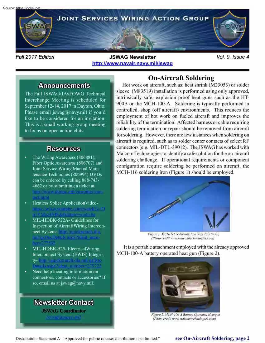
http://quicksearch.dlamil/qsDocDetailsaspx?ident number=279725 Need help locating information on connectors, contacts or accessories? If so, email us at jswag@navy.mil On-Aircraft Soldering Hot work on aircraft, such as: heat shrink (M23053) or solder sleeve (M83519) installation is performed using only approved, intrinsically safe, explosion proof heat guns such as the HT900B or the MCH-100-A. Soldering is typically performed in controlled, shop (off aircraft) environments. This reduces the employment of hot work on fueled aircraft and improves the reliability of the termination. Affected harness or cable requiring soldering termination or repair should be removed from aircraft for soldering. However, there are few instances when soldering on aircraft is required, such as to solder center contacts of select RF connectors (e.g MIL-DTL-39012) The JSWAG has worked with Malcom Technologies to identify a safe solution for the on-aircraft soldering challenge. If operational requirements
or component configuration require soldering be performed on aircraft, the MCH-116 soldering iron (Figure 1) should be employed. Figure 1. MCH-116 Soldering Iron with Tips (inset) (Photo credit www.malcomtechnologiescom) It is a portable attachment employed with the already approved MCH-100-A battery operated heat gun (Figure 2). Newsletter Contact JSWAG Coordinator jswag@navy.mil Figure 2. MCH-100-A Battery Operated Heatgun (Photo credit www.malcomtechnologiescom) Distribution: Statement A- “Approved for public release; distribution is unlimited.” see On-Aircraft Soldering, page 2 JSWAG Newsletter / Volume 9, Issue 4 On-Aircraft Soldering (cont) The MCH-116 has been tested and meets the explosion proof (MIL-STD-810) and electromagnetic interference (MILSTD-461) requirements. The MCH-116 plugs into the power supply of the Navy-fielded MCH-100-A using a quick disconnect plug. The 50 Watt soldering iron provides up to 4 hours of operation for typical soldering tasks The
kit comes with three different shaped replaceable tips (Figure 1) offering versatile application at temperatures between 595° and 1000° F depending on the tip employed. The soldering iron is expected to reach operating temperatures in 6-8 minutes During suitability testing, it melted solder (Sn60Pb40) within two minutes. NSN (3439-01-536-6370) has been assigned and the joint service, general wiring maintenance manual update is awaiting publication in Change 3. Before performing hot work on aircraft, specific authorization from Aviation Gas Free Engineer (AVGFE) or Gas Free Engineer (GFE) is required. Aircraft with open fuel cells, broken or open fuel lines must be certified gas free in accordance with NAVAIR 01-1A-35 or T.O 1-1-3 Consult applicable platform-specific technical manuals for safety and operational requirements and also consult Cognizant Engineering Authority (CAE) for guidance before soldering. In some applications, crimped termination alternatives may provide superior
performance to soldered terminations (MIL-STD-217). CAE may provide component substitution guidance such as upgrading a solder type to a crimped type connector. M85049/128 Shield Termination Bands The typical metallic shield over-braid termination for protected wire harnesses employs the M85049/128 steel band. A dedicated banding tool is used to install the metal band used to terminate and secure metallic over-braid. The following application update/limitation is being made. Only the 1/4” wide bands are approved for use to terminate shielding onto M85049 circular accessories (e.g backshells and shield splice / split support rings). The 1/8” wide bands may only be employed when required by the platform-specific manual or harness drawing. In all applications, bands must be double looped. The AS85049/128 specification is being updated to reflect this application restriction. Note- the 1/8” wide bands provide only half of the strength/performance of the 1/4” wide ones and are
restricted for use on low profile, composite backshells. The low profile backshells are not qualified AS85049 accessories, thus not approved for aerospace applications. The 1/4” wide, approved bands are available in pre-coiled and flat configurations, in both one step and two step configurations. Tool configuration and corresponding band part number are listed in Table 1 below. The NA 011A-505-1 is being updated to reflect this change A. ONE STEP BANDING B. TWO STEP BANDING Find the Answer Current Question: Which circuit breaker lockout / deactivation device is the only one approved for in-flight use? Resources: NA 01-1A-505-1, WP 028 00, para 67a(1), page 11. Answer will be provided in Winter 2018 Newsletter Previous Question/Answer: Which tool is the M22759/11-20-9 wire stripped with? Tool number AS5768-1-T8, Blade number AS5768-1-B8 References: NA 01-1A-505-1, WP 009 00