Comments
No comments yet. You can be the first!
What did others read after this?


Content extract
Newman2 18/2/04 11:57 am Page 1 Feature The safety of shipborne helicopter operation Dr Simon Newman Senior Lecturer in Helicopter Engineering Aerospace Engineering, School of Engineering Sciences, University of Southampton he helicopter has been in existence, in its present form, for over fifty years and it possesses a wide variety of operational use. This paper focuses on the development of the shipborne helicopter which requires controlled flight in a very complex and potentially dangerous atmospheric environment surrounding a ship's flight deck. This type of helicopter requires dedicated design features to enable appropriate missions to be successfully achieved. It is an interesting feature of the shipborne helicopter that operational problems are as important with the aircraft in contact with the deck as to flight above it. Also there are problems which begin with extracting the aircraft to the hangar to its eventual reinsertion. The avoidance of unfavourable
characteristics has, over the years, resulted in an air vehicle where the aeroelastic properties of the rotor blades govern the operation. The magnitude of the wind speeds over a ship's deck, coupled with the varying rotor speed during the engage and disengage parts of a sortie, expose the rotors to dangerous blade deflections which have, in the past, resulted in damage to the aircraft and, in severe cases, fatalities. The operation of helicopters from ships began just before World War II. From that time, the helicopter has carved a niche principally because of its capability of flight in regimes impossible for any other air vehicle. A typical example is shown in Figure 1. This has resulted in the operation of helicopters under conditions which have increased in difficulty dramatically. An important corollary to this last remark is that the weather conditions under which the helicopter is expected to fly have become more severe. All of these points have caused shipborne operation
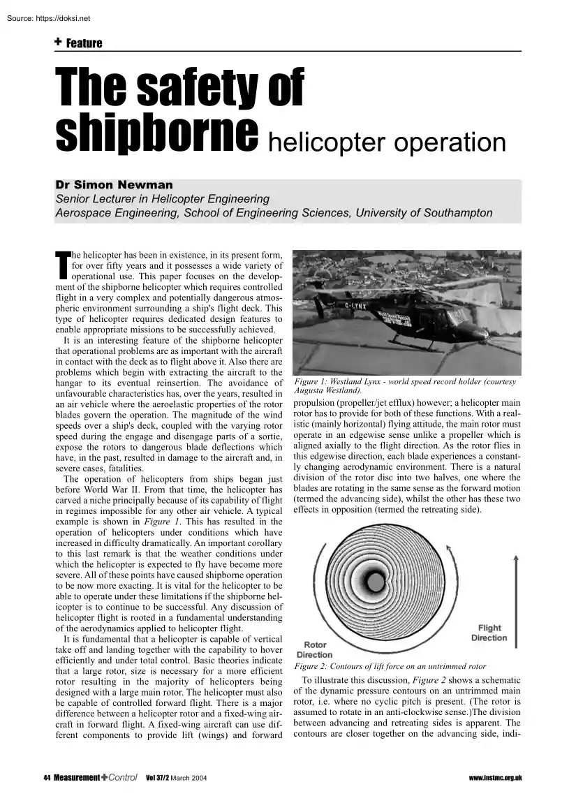
to be now more exacting. It is vital for the helicopter to be able to operate under these limitations if the shipborne helicopter is to continue to be successful. Any discussion of helicopter flight is rooted in a fundamental understanding of the aerodynamics applied to helicopter flight. It is fundamental that a helicopter is capable of vertical take off and landing together with the capability to hover efficiently and under total control. Basic theories indicate that a large rotor, size is necessary for a more efficient rotor resulting in the majority of helicopters being designed with a large main rotor. The helicopter must also be capable of controlled forward flight. There is a major difference between a helicopter rotor and a fixed-wing aircraft in forward flight. A fixed-wing aircraft can use different components to provide lift (wings) and forward T 44 Vol 37/2 March 2004 Figure 1: Westland Lynx - world speed record holder (courtesy Augusta Westland). propulsion
(propeller/jet efflux) however; a helicopter main rotor has to provide for both of these functions. With a realistic (mainly horizontal) flying attitude, the main rotor must operate in an edgewise sense unlike a propeller which is aligned axially to the flight direction. As the rotor flies in this edgewise direction, each blade experiences a constantly changing aerodynamic environment. There is a natural division of the rotor disc into two halves, one where the blades are rotating in the same sense as the forward motion (termed the advancing side), whilst the other has these two effects in opposition (termed the retreating side). Figure 2: Contours of lift force on an untrimmed rotor To illustrate this discussion, Figure 2 shows a schematic of the dynamic pressure contours on an untrimmed main rotor, i.e where no cyclic pitch is present (The rotor is assumed to rotate in an anti-clockwise sense.)The division between advancing and retreating sides is apparent. The contours are closer
together on the advancing side, indi- www.instmcorguk Newman2 18/2/04 11:57 am Page 2 Feature cating thrust potential, whilst on the retreating side of the disc the contours are more widely spaced, giving a smaller ability to generate thrust. Figure 4: Location of rotor head hinges. Figure 3: Contours of lift force on a trimmed rotor. Figure 3 shows the same rotor only with appropriate cyclic pitch applied to give sufficient forward rotor disc tilt to provide the necessary propulsion. The concentration of thrust potential on the advancing side is apparent in Figure 2, whilst the cyclic pitch applied in Figure 3 shows how this has to be discarded. To make matters worse, the small circle, within the rotor perimeter, is a region of the rotor disc where the forward speed exceeds the rotational speed and the flow approaches the blades from the wrong direction. For this reason, it is known as the reverse flow region It is for these reasons that the helicopter has been dogged by
the limitation in its potential forward speed over its entire history. To set this result in perspective, a comparison of helicopter and fixed-wing aircraft world speed records is informative. On August 11th 1986, company test pilot Trevor Egginton, and his Flight Engineer, Derek Clews, flew a Westland Lynx helicopter over a measured corridor on the Somerset levels to gain the world speed record for its class of nearly 250 mph, see Figure 1. Naturally, this proved a significant moment in the history of the Lynx, both in concept and design, but also a vindication of an advanced rotor system. Although the record attempt was achieved with a flight test programme of only one week, many years of development work were encapsulated in this achievement. As a result of the success, this rotor design is now fitted to the latest marks of the Lynx airframe and the new naval helicopter replacing the Sea King, namely the Merlin. A fixed-wing aircraft exceeded this speed on 4th November 1923 when a
Lt Brown flew a Curtiss HS D-12 over Mitchell Field, New York, and achieved 260 mph. The 63-year difference in these world speed record achievements is a graphic illustration of the complexity of the aerodynamics of a helicopter rotor, which is a perfect example of compromise in design and operation. This provides the basic reason for the severe limitation to the forward speed capability During its world speed record flight, parts of the Lynx main rotor blades were seeing considerable changes in aerodynamic environment. A blade tip would observe speed changes over it from low speed as seen on a small light aircraft to the speed of sound as experienced by a fighter aeroplane. The angles of attack would also vary from a low setting as seen by an aircraft during its ground roll to a high incidence comparable with a delta wing, such www.instmcorguk as Concorde, coming in to land. This would be repeating at a frequency of approximately 5 times per second. The previous discussion shows
that the basic rotor environment is particularly complex which will be exacerbated by its interaction with flows off bluff bodies which are the norm for shipborne operation from ship-based flight decks. Rotorcraft were initially of the autogyro configuration which uses a main rotor to supply the lift but requires a propeller to give the forward propulsion. Early types encountered the classic problem of where the advancing side receives a higher dynamic pressure than the retreating side. Unless there are adjustments made, a rolling moment will be generated which will prevent controlled flight. An early rotorcraft pioneer, Juan de la Cierva, started life working on bridge trusses. His experiences of using pinned joints to isolate moments allowed a solution to this problem by attaching the rotor blades to the central hub by using hinges (see Figure 5). These hinges allow the blades to move freely in a sense at right angles to the plane of the rotor disc. This motion is termed flapping and
the connecting hinge the flapping hinge This will obviously relieve the hub of the rolling moment since the blades are now isolated from transmitting the moments to the hub. The flapping hinges also prevent direct control of the rotor blades through the blade/hub connection. The blades are now only controllable by adjusting the balance between the aerodynamic and the centrifugal forces. The centrifugal forces are considerable in magnitude since centripetal accelerations of the order of 750-1000g can be experienced at the main rotor blade tip. The balance is achieved by setting off the centrifugal effects by the aerodynamic lift generated by the blades themselves. Figure 5: Contours of lift force on a trimmed rotor A survey of the various helicopter types in existence would show that the vast majority are of the single main and tail rotor configuration and, for this reason, the paper focuses on this type. The control of this type of helicopter is achieved using both rotors. The main
rotor is responsible for the degrees of freedom of heave, sway, surge, pitch and roll. The tail rotor is responsible for yaw In viewing the role of the main rotor, it is usual to regard the thrust Vol 37/2 March 2004 45 Newman2 18/2/04 11:57 am Page 3 Feature Figure 6: Sikorsky S61NM hovering - rotor blades coned. Figure 7: Sikorsky S61NM with flat rotor (zero thrust). force as being perpendicular to the rotor plane. The control of the aircraft is now achieved by controlling the thrust vector. The vector is defined by the variation of the magnitude of the thrust force and its direction via the orientation of the disc plane Control of the vector is achieved by the pilot using two pitch change mechanisms: Control of the main rotor thrust force by applying uniform pitch changes to all of the blades (collective pitch). Variation of the pitch of each blade as it travels around the azimuth (cyclic pitch). This allows the main rotor disc attitude to be controlled. Figure 8
shows the Merlin prototype PP5 in forward flight. The difference in blade pitch angles can be readily seen, indicating the application of cyclic pitch. Figure 9: Sikorsky S61NM tail rotor. Figure 8: Merlin prototype PP5 in forward flight. Using these two controls allows the rotor to align itself to provide the thrust vector required by the pilot. The final rotor control of the pilot is the pedals which alter the pitch setting on the tail rotor and thereby adjust the thrust. This thrust causes the yawing moment to vary and combined with the reaction torque from the engine and transmission gives rise to the yaw behaviour of the aircraft. Figure 9 shows a typical tail rotor installation at the top of the fin. Whilst the tail rotor is only required to provide yaw control, it is placed in situations which hamper the achievement of that control. Gyroscopic precession during rapid yaw manueouvres limits the thrust potential. In addition, interference with the fuselage acts as a
disadvantage and the main rotor downwash passing over the rear tail boom structure can indeed cause the tail rotor to run out of available thrust during modest sideways flight. A strake is often used to avoid this problem. It is a plate affixed to the tail boom which interrupts the flows which generate the adverse force from the tail boom itself which causes the 46 Vol 37/2 March 2004 Figure 10: EH101 PP5 tail boom strake. problem. A typical installation is shown in Figure 10 When operating on board ship, a helicopter will often require storing. The large footprint of the rotors will require a folding system. Figure 11 shows the powered main rotor folded. The ability to fold remotely is becoming essential with large helicopters operating from small ships. The blades are inaccessible to the ground crew in these situations. The length of the helicopter is usually shortened by folding the rear portion of the tail boom, fin and tail rotor. Such a folding mechanism is shown in Figure 12
The drive and control connections are broken as the tail folds, subsequently reconnecting when the tail unit is restored. www.instmcorguk Newman2 18/2/04 11:57 am Page 4 Feature Figure 11: Sea King with rotors folded. Figure 13: RFA Olwen (Courtesy of Royal Navy). magic quiescent period is of major importance which the pilot aims to use. The concept is that the ship will undergo a series of motions which repeat every few cycles. This has been shown to be essentially predictable. The ultimate situation is that the helicopter achieves its hovering state over the ship’s flight deck at the instant that the quiescent point is reached (where the ship is temporarily stationary), allowing a vertical descent to the deck to be completed relatively easily. Figure 12: Wessex tail fold. The Ship Environment The environment in which the shipborne helicopter is expected to operate is never easy and at times distinctly hostile. Examples of flight deck are shown in Figures 1316 Figure
13 shows that of an O Class Royal Fleet Auxiliary. The large box-like structures positioned bow side of the flight deck can cause flow separations as indeed can the funnel. Also of note is the height of the deck above the sea. Any rolling of the ship will cause considerable sideways velocity of the deck under the landing helicopter. Pitching motion will cause vertical translation of the flight deck. This can induce a piloting problem If say the pilot is focused on the hangar whilst preparing to land and the ship pitches bow up, the deck will move downwards relative to the helicopter. The pilot can interpret this as the helicopter moving upwards, and correct with a reduction in collective pitch. As the helicopter moves downward, relative to earth, the ship will pitch bow down as the cycle continues resulting in a large vertical closing velocity of the helicopter and the deck. This is one of the effects which is avoided by close observation of the ship from the helicopter. The
www.instmcorguk Figure 14: RFA Gold Rover (Courtesy of Royal Navy). Figure 14 shows a Rover Class RFA and the vertical sides of the hull below the flight deck will cause vertical flow components to be generated as the air passes over the ship. These vertical air flows can cause considerable problems in flight around the deck and operation with the undercarriage in contact with the deck. Figure 15: HMS Liverpool (Courtesy of Royal Navy) Figure 15 shows a more conventional warship with the limited flight deck shown at the stern. The effects on the airflow caused by the superstructure and hull sides can be appreciated. Vol 37/2 March 2004 47 Newman2 18/2/04 11:57 am Page 5 Feature Figure 18 shows the air flow over a Rover Class RFA deck with the wind coming from the rear port quarter. Again the vertical flow component is well shown. Operating Procedure Figure 16: HMS Iron Duke (Courtesy of Agusta Westland). Figure 16 shows the first Merlin helicopter on the deck of a Type
23 frigate. The relative size of the rotor to the deck width is significantly higher in this situation than with the previous cases. The manner in which the rotor overhangs the hull sides will give the disturbed airflow a larger proportion of the rotor disc to influence. The operating procedure is concentrated on take off and landing. Take off is relatively straightforward The helicopter must lift off the deck and transit away from the ship being mindful of airflows coming off the ship. The real difficulty comes with the landing phase. For this reason discussion is concentrated on this part of the flight envelope. The effects of the ship flows have a large influence on the landing method. The initial approach is down a 3° glide slope (using a light indicator over the hangar door) to a position on the port side of the ship, at a height level with the top edge of the hangar door and about one rotor diameter off the ship-side. The longitudinal position is indicated by a lateral line on
the deck. The approach is on the port side as a helicopter pilot uses the right hand seat. The pilot predicts when the quiescent point will be reached and transits across the ship in front of the hangar approximately in the centre of the deck. Under command of an officer on the deck, the helicopter is then brought to land with a vertical descent. The landing is usually accomplished with a not inconsiderable downward velocity firmly planting the helicopter on the deck. This will require a specially designed undercarriage which will kill the energy of the descending helicopter and prevent any recoil from the compressed undercarriage oleos. This procedure is shown in images and diagrams in Figures 19-24 It is noteworthy that the Lynx and the later Merlin helicopters are fitted with a decklock. This is a device fitted to the underside of the helicopter fuselage which extends and secures the airframe to the deck. This is of major use when large amounts of deck motion exist. Figure 17:
Smoke flow over wind tunnel model of O-Class RFA. Figure 17 shows a smoke trace indicating the flow over an O Class deck with the wind coming from the port side at 90° to the ship’s centreline. The vertical component is apparent Figure 18: Smoke flow over wind tunnel model of Rover Class RFA. 48 Vol 37/2 March 2004 Figure. 19: Merlin approaching Type 23 frigate (courtesy of Agusta Westland). www.instmcorguk Newman2 18/2/04 11:58 am Page 6 Feature Rotor – Ship Interacting Flows Figure 20: Merlin in lateral transit (courtesy of Royal Navy). Figure 21: Approach procedure. One factor which has recently been observed in wind tunnel tests is the degree of aerodynamic interaction between the flow over the deck and that passing through the rotor disc. The setup is shown in Figure 25 with the model rotor positioned behind the ship’s flight deck. Figure 26 shows the rotor in operation above the deck. The stripe is the vertical laser sheet which determines the plane in
which the flow is measured. As an example, when the flow passes off the hangar roof with a bow wind, it descends to the deck to reattach approximately half the length of the deck behind the hangar door. This divides the flow into that passing off the stern of the ship and that forming a recirculating region behind the hangar face. The dividing line between these two flow types is not steady and the reattachment point oscillates in a longitudinal sense. A typical result is shown in Figure 27 When the rotor disc moves into this region the interaction is profound. All of these effects become very problematic as the rotor’s aerodynamic behaviour will vary under these conditions, requiring a considerable amount of pilot workload. The type of flow obtained is shown in Figure 28 Figure 29 shows the type of flow obtained with the wind at 90° to the ship’s centreline. Again a divided flow is seen In this instance, however, a high degree of vertical component is now present which apart from
influencing the rotor performance has a major influence on rotor blade behaviour during engagement and disengagement. Figure 22: Lateral transit and touchdown procedure. Figure 25: Model rotor and ship in wind tunnel. Fig. 23: Westland Lynx prior to touchdown (courtesy of Agusta Westland) Figure 24: Westland Lynx immediately after touchdown (courtesy of Agusta Westland). www.instmcorguk Figure 26: Laser sheet over rotor and ship (courtesy Bruce Lumsden). Vol 37/2 March 2004 49 Newman2 18/2/04 11:58 am Page 7 Feature Another example of ship and rotor flow interaction is shown in Figure 31. Here the helicopter is transiting laterally across to the flight deck A wind at 90° is present The downwash from the rotor forms a bubble underneath the rotor disc and the flow approaching the windward side of the deck is accelerated through the decreasing gap between the bubble and the deck edge. This forms what is known as a "pressure wall" which tends to repel the
advancing helicopter. This requires an extra amount of control which can result in the helicopter punching through the pressure wall and transiting across the deck too far. This will require a correction in lateral position which may put the timing of the landing off the predicted quiescent point. Figure 27: Hangar flow over flight deck. Figure 31: Flows giving pressure wave. Figure 28: PIV map of flow over ship and rotor. As a final discussion of the rotor ship interaction, Figures 32 & 33 show the results of a force test using the same rotor and ship models as previously discussed. The height of the rotor is approximately that just hovering above the deck. The figures show surface plots of Figure of Merit. This gives an indication of the efficiency at which the rotor is generating thrust. Figure 32 shows the results with zero wind The base is approximately the rear half of the flight deck which extends from –C to C. The plot is fairly symmetric and the loss of ground effect
is apparent as the rotor moves off the deck losing the ground cushion. Figure 29: LDA flow measurement over ship's flight deck Figure 30 summarises the various types of flow seen around a ship’s flight deck in wind tunnel experiments. Each is highly influenced by the incident wind direction and ship geometry. Figure 32: Figure of merit contours with zero wind. Figure 30: Typical flows over ship. 50 Vol 37/2 March 2004 In Figure 33, however, a wind of 6m/s (tunnel speed) acts at 20° from the starboard direction. As the rotor moves off the port deck edge, a large dip in the Figure of Merit can be seen. In this instance the pilot must be mindful of the rapid loss in performance and arrest any tendency for the helicopter to drop. Cases have occurred where a downward flow has caused to the pilot to over-torque the transmission in order to save the aircraft www.instmcorguk Newman2 18/2/04 11:58 am Page 8 Feature Figure 35: Droop stop and anti-flap restraints. Figure
33: Figure of merit contours with wind at 20 º. Rotor Engagement & Disengagement At the beginning and end of a mission, helicopter rotors must be accelerated to operating speed and subsequently decelerated to a stop. During these parts of the mission, the rotor will be rotating at low rotor speeds, which if coupled with a high wind over the ship can induce considerable blade motion. This phenomenon is known as blade sailing and can cause the blades to deflect to such an extent that impact with the fuselage can occur. Because of this, the phenomenon is known as tunnel strikes in the USA. As previously explained, the rotor blades are subject to the aerodynamic lift and the centrifugal forces. At low rotor speeds the centrifugal force will be much reduced from normal operation and, if there is a high enough wind speed generating vertical wind shears, the two forces will go out of balance and the blades will tend to sail. Examples of high blade deflection are shown in Figure 34. In
order to restrain the blades, articulated rotors are fitted with devices which restrain physically the blade flapping motion. These are known as droop stops (downward motion) and anti-flap assembly (upward motion). These are fitted under each blade. Figure 35 shows their location on a Wessex main rotor hub. Figure 36: Modelling of hub restraints. Figure 37: Rotor engagement, 4 Figure 38: Blade sailing - Sea modes. King disengagement, 4 modes. Figure 39: Sea King engage- Figure 40: Sea King disengagement, fundamental mode. ment, fundamental mode. Figure 34: Examples of blade sailing (courtesy Royal Navy). Effectively they act as high rate springs as shown in Figure 36. Theoretical and experimental investigations have taken place on this phenomenon and interesting features are found. Figure 37 shows the blade tip deflection for a Sea King main rotor. The large downward movement at the low rotor speeds can be seen. This equates approximately to a rotor speed of 15% of normal. The
blade motion was defined by four flapping mode shapes. The equivalent disengagement www.instmcorguk behaviour is shown in Figure 38. It is an apparent paradox that the blades are still moving greatly even though they are restrained at the hub by the droop and anti-flap assemblies. However, closer examination of the detailed blade behaviour shows that the modes respond such that the displacement at the hub restraint position is minimised – which causes the response to sum at the tip giving the large blade deflections. If only the fundamental mode is used then the equivalent blade tip response is shown in Figures 39 & 40. The response is now severely reduced. The essential detail Vol 37/2 March 2004 51 Newman2 18/2/04 11:58 am Page 9 Feature is that the fundamental mode and first harmonic act in opposition. This allows the reduction in motion at the root end but magnifies the effect at the tip. In more modern rotors, because of advanced construction techniques, the
second mode is more difficult to trigger. In this way the blade flapping motion is strongly under the influence of the hub restraints. The disadvantage is that now the number of blade interactions with the hub restraints are considerably more, moving the problem from blade motion to hub wear and tear. Similar effects can be experienced on folded blades. The problem still occurs with the large aerodynamic loads generated by the wind conditions In this case the blade motion is now resisted by the control system. Conclusions The above discussion has shown that the operation of a helicopter from a ship is a very demanding role. Flows over typical ship flight decks are complicated and unsteady. Coupling these with the considerable downwash generated by a helicopter main rotor causes a high degree of interaction with subsequent influences on performance. The requirements of a shipborne helicopter are, in order: ❐ removal from the hangar ❐ spreading the rotors ❐ engaging ❐ take off
❐ fly away ❐ flight in ❐ traversing ❐ landing ❐ disengaging ❐ folding ❐ replacement in the hangar. Each part of the operation has its own dangers and requirements for safe operation. The complications are such that future research will continue into these aerodynamic and dynamic interactions, effects on performance and to the design of future helicopters for shipborne use. Bibliography 1. Westland Lynx/Ship Interface WHL Brochure B1163 ISS 2 „ Westland Helicopters Ltd., June 1985 2. P Day A Study of the Wind Flow Surrounding a Ship's Flight Deck. Project Report 1349 1996, Department of Aeronautics & Astronautics, University of Southampton. 3. JD Chalkley The Influence of Rotor Downwash on the Flow over a Ship's Flight Deck. Project Report 1403 1997, Department of Aeronautics & Astronautics, University of Southampton. 4. NH Wakefield, SJ Newman, PA Wilson CFD Predictions of the Influence of External Airflow on Helicopter Operations when Operating from
Ship Flight Decks, Paper 30, International Powered Lift Conference, 2-4 September 1998, London 5. SJ Newman An Investigation into the Phenomenon of Helicopter Blade Sailing, Ph.D Thesis, University of Southampton, March 1995 6. SJ Newman The Problems of Rotor Engagement & Disengagement of a Shipborne Helicopter. Journal of Naval Science, Vol. 20, No 1, 1994, pp 56-64 7. SJ Newman and WR Walker The Influence of blade flexibility on the sailing behaviour of helicopter rotors Journal of Defence Science, 4, 1996, 498-507. 8. SJ Newman A Theoretical Model for Predicting the Blade Sailing Behaviour of a Semi-Rigid Rotor Helicopter. Vertica, Vol 14, No 4, 1990, pp 531-544 9. SJ Newman The Application of a Theoretical Blade Sailing Model to Predict the Behaviour of Articulated Helicopter Rotors. Journal of the Royal Aeronautical Society, Vol. 96, no 956, June/July 1992, pp 233-239 10. SJ Newman The Verification of a Theoretical Helicopter Rotor Blade Sailing Method By Means of Wind Tunnel
Testing. Journal of the Royal Aeronautical Society, Vol. 99, No 982, February 1995, pp 41-51 11. S Newman The Phenomenon of Helicopter Blade Sailing, Journal of Aerospace Engineering Part G, Vol. 213, No G6, 1999, pp 347-364, ISSN 0954-4100 “The essential resource for the instrumentation and control industry’ The Instrument Engineer’s Yearbook 2004 is now available. For more details contact: The Publications Department, InstMC 87 Gower Street, London WC1E 6AF Tel: 020 7387 4949 Fax: 020 7388 8431 Email: publications@instmc.orguk Website: wwwinstmcorguk 52 Vol 37/2 March 2004 www.instmcorguk
characteristics has, over the years, resulted in an air vehicle where the aeroelastic properties of the rotor blades govern the operation. The magnitude of the wind speeds over a ship's deck, coupled with the varying rotor speed during the engage and disengage parts of a sortie, expose the rotors to dangerous blade deflections which have, in the past, resulted in damage to the aircraft and, in severe cases, fatalities. The operation of helicopters from ships began just before World War II. From that time, the helicopter has carved a niche principally because of its capability of flight in regimes impossible for any other air vehicle. A typical example is shown in Figure 1. This has resulted in the operation of helicopters under conditions which have increased in difficulty dramatically. An important corollary to this last remark is that the weather conditions under which the helicopter is expected to fly have become more severe. All of these points have caused shipborne operation
to be now more exacting. It is vital for the helicopter to be able to operate under these limitations if the shipborne helicopter is to continue to be successful. Any discussion of helicopter flight is rooted in a fundamental understanding of the aerodynamics applied to helicopter flight. It is fundamental that a helicopter is capable of vertical take off and landing together with the capability to hover efficiently and under total control. Basic theories indicate that a large rotor, size is necessary for a more efficient rotor resulting in the majority of helicopters being designed with a large main rotor. The helicopter must also be capable of controlled forward flight. There is a major difference between a helicopter rotor and a fixed-wing aircraft in forward flight. A fixed-wing aircraft can use different components to provide lift (wings) and forward T 44 Vol 37/2 March 2004 Figure 1: Westland Lynx - world speed record holder (courtesy Augusta Westland). propulsion
(propeller/jet efflux) however; a helicopter main rotor has to provide for both of these functions. With a realistic (mainly horizontal) flying attitude, the main rotor must operate in an edgewise sense unlike a propeller which is aligned axially to the flight direction. As the rotor flies in this edgewise direction, each blade experiences a constantly changing aerodynamic environment. There is a natural division of the rotor disc into two halves, one where the blades are rotating in the same sense as the forward motion (termed the advancing side), whilst the other has these two effects in opposition (termed the retreating side). Figure 2: Contours of lift force on an untrimmed rotor To illustrate this discussion, Figure 2 shows a schematic of the dynamic pressure contours on an untrimmed main rotor, i.e where no cyclic pitch is present (The rotor is assumed to rotate in an anti-clockwise sense.)The division between advancing and retreating sides is apparent. The contours are closer
together on the advancing side, indi- www.instmcorguk Newman2 18/2/04 11:57 am Page 2 Feature cating thrust potential, whilst on the retreating side of the disc the contours are more widely spaced, giving a smaller ability to generate thrust. Figure 4: Location of rotor head hinges. Figure 3: Contours of lift force on a trimmed rotor. Figure 3 shows the same rotor only with appropriate cyclic pitch applied to give sufficient forward rotor disc tilt to provide the necessary propulsion. The concentration of thrust potential on the advancing side is apparent in Figure 2, whilst the cyclic pitch applied in Figure 3 shows how this has to be discarded. To make matters worse, the small circle, within the rotor perimeter, is a region of the rotor disc where the forward speed exceeds the rotational speed and the flow approaches the blades from the wrong direction. For this reason, it is known as the reverse flow region It is for these reasons that the helicopter has been dogged by
the limitation in its potential forward speed over its entire history. To set this result in perspective, a comparison of helicopter and fixed-wing aircraft world speed records is informative. On August 11th 1986, company test pilot Trevor Egginton, and his Flight Engineer, Derek Clews, flew a Westland Lynx helicopter over a measured corridor on the Somerset levels to gain the world speed record for its class of nearly 250 mph, see Figure 1. Naturally, this proved a significant moment in the history of the Lynx, both in concept and design, but also a vindication of an advanced rotor system. Although the record attempt was achieved with a flight test programme of only one week, many years of development work were encapsulated in this achievement. As a result of the success, this rotor design is now fitted to the latest marks of the Lynx airframe and the new naval helicopter replacing the Sea King, namely the Merlin. A fixed-wing aircraft exceeded this speed on 4th November 1923 when a
Lt Brown flew a Curtiss HS D-12 over Mitchell Field, New York, and achieved 260 mph. The 63-year difference in these world speed record achievements is a graphic illustration of the complexity of the aerodynamics of a helicopter rotor, which is a perfect example of compromise in design and operation. This provides the basic reason for the severe limitation to the forward speed capability During its world speed record flight, parts of the Lynx main rotor blades were seeing considerable changes in aerodynamic environment. A blade tip would observe speed changes over it from low speed as seen on a small light aircraft to the speed of sound as experienced by a fighter aeroplane. The angles of attack would also vary from a low setting as seen by an aircraft during its ground roll to a high incidence comparable with a delta wing, such www.instmcorguk as Concorde, coming in to land. This would be repeating at a frequency of approximately 5 times per second. The previous discussion shows
that the basic rotor environment is particularly complex which will be exacerbated by its interaction with flows off bluff bodies which are the norm for shipborne operation from ship-based flight decks. Rotorcraft were initially of the autogyro configuration which uses a main rotor to supply the lift but requires a propeller to give the forward propulsion. Early types encountered the classic problem of where the advancing side receives a higher dynamic pressure than the retreating side. Unless there are adjustments made, a rolling moment will be generated which will prevent controlled flight. An early rotorcraft pioneer, Juan de la Cierva, started life working on bridge trusses. His experiences of using pinned joints to isolate moments allowed a solution to this problem by attaching the rotor blades to the central hub by using hinges (see Figure 5). These hinges allow the blades to move freely in a sense at right angles to the plane of the rotor disc. This motion is termed flapping and
the connecting hinge the flapping hinge This will obviously relieve the hub of the rolling moment since the blades are now isolated from transmitting the moments to the hub. The flapping hinges also prevent direct control of the rotor blades through the blade/hub connection. The blades are now only controllable by adjusting the balance between the aerodynamic and the centrifugal forces. The centrifugal forces are considerable in magnitude since centripetal accelerations of the order of 750-1000g can be experienced at the main rotor blade tip. The balance is achieved by setting off the centrifugal effects by the aerodynamic lift generated by the blades themselves. Figure 5: Contours of lift force on a trimmed rotor A survey of the various helicopter types in existence would show that the vast majority are of the single main and tail rotor configuration and, for this reason, the paper focuses on this type. The control of this type of helicopter is achieved using both rotors. The main
rotor is responsible for the degrees of freedom of heave, sway, surge, pitch and roll. The tail rotor is responsible for yaw In viewing the role of the main rotor, it is usual to regard the thrust Vol 37/2 March 2004 45 Newman2 18/2/04 11:57 am Page 3 Feature Figure 6: Sikorsky S61NM hovering - rotor blades coned. Figure 7: Sikorsky S61NM with flat rotor (zero thrust). force as being perpendicular to the rotor plane. The control of the aircraft is now achieved by controlling the thrust vector. The vector is defined by the variation of the magnitude of the thrust force and its direction via the orientation of the disc plane Control of the vector is achieved by the pilot using two pitch change mechanisms: Control of the main rotor thrust force by applying uniform pitch changes to all of the blades (collective pitch). Variation of the pitch of each blade as it travels around the azimuth (cyclic pitch). This allows the main rotor disc attitude to be controlled. Figure 8
shows the Merlin prototype PP5 in forward flight. The difference in blade pitch angles can be readily seen, indicating the application of cyclic pitch. Figure 9: Sikorsky S61NM tail rotor. Figure 8: Merlin prototype PP5 in forward flight. Using these two controls allows the rotor to align itself to provide the thrust vector required by the pilot. The final rotor control of the pilot is the pedals which alter the pitch setting on the tail rotor and thereby adjust the thrust. This thrust causes the yawing moment to vary and combined with the reaction torque from the engine and transmission gives rise to the yaw behaviour of the aircraft. Figure 9 shows a typical tail rotor installation at the top of the fin. Whilst the tail rotor is only required to provide yaw control, it is placed in situations which hamper the achievement of that control. Gyroscopic precession during rapid yaw manueouvres limits the thrust potential. In addition, interference with the fuselage acts as a
disadvantage and the main rotor downwash passing over the rear tail boom structure can indeed cause the tail rotor to run out of available thrust during modest sideways flight. A strake is often used to avoid this problem. It is a plate affixed to the tail boom which interrupts the flows which generate the adverse force from the tail boom itself which causes the 46 Vol 37/2 March 2004 Figure 10: EH101 PP5 tail boom strake. problem. A typical installation is shown in Figure 10 When operating on board ship, a helicopter will often require storing. The large footprint of the rotors will require a folding system. Figure 11 shows the powered main rotor folded. The ability to fold remotely is becoming essential with large helicopters operating from small ships. The blades are inaccessible to the ground crew in these situations. The length of the helicopter is usually shortened by folding the rear portion of the tail boom, fin and tail rotor. Such a folding mechanism is shown in Figure 12
The drive and control connections are broken as the tail folds, subsequently reconnecting when the tail unit is restored. www.instmcorguk Newman2 18/2/04 11:57 am Page 4 Feature Figure 11: Sea King with rotors folded. Figure 13: RFA Olwen (Courtesy of Royal Navy). magic quiescent period is of major importance which the pilot aims to use. The concept is that the ship will undergo a series of motions which repeat every few cycles. This has been shown to be essentially predictable. The ultimate situation is that the helicopter achieves its hovering state over the ship’s flight deck at the instant that the quiescent point is reached (where the ship is temporarily stationary), allowing a vertical descent to the deck to be completed relatively easily. Figure 12: Wessex tail fold. The Ship Environment The environment in which the shipborne helicopter is expected to operate is never easy and at times distinctly hostile. Examples of flight deck are shown in Figures 1316 Figure
13 shows that of an O Class Royal Fleet Auxiliary. The large box-like structures positioned bow side of the flight deck can cause flow separations as indeed can the funnel. Also of note is the height of the deck above the sea. Any rolling of the ship will cause considerable sideways velocity of the deck under the landing helicopter. Pitching motion will cause vertical translation of the flight deck. This can induce a piloting problem If say the pilot is focused on the hangar whilst preparing to land and the ship pitches bow up, the deck will move downwards relative to the helicopter. The pilot can interpret this as the helicopter moving upwards, and correct with a reduction in collective pitch. As the helicopter moves downward, relative to earth, the ship will pitch bow down as the cycle continues resulting in a large vertical closing velocity of the helicopter and the deck. This is one of the effects which is avoided by close observation of the ship from the helicopter. The
www.instmcorguk Figure 14: RFA Gold Rover (Courtesy of Royal Navy). Figure 14 shows a Rover Class RFA and the vertical sides of the hull below the flight deck will cause vertical flow components to be generated as the air passes over the ship. These vertical air flows can cause considerable problems in flight around the deck and operation with the undercarriage in contact with the deck. Figure 15: HMS Liverpool (Courtesy of Royal Navy) Figure 15 shows a more conventional warship with the limited flight deck shown at the stern. The effects on the airflow caused by the superstructure and hull sides can be appreciated. Vol 37/2 March 2004 47 Newman2 18/2/04 11:57 am Page 5 Feature Figure 18 shows the air flow over a Rover Class RFA deck with the wind coming from the rear port quarter. Again the vertical flow component is well shown. Operating Procedure Figure 16: HMS Iron Duke (Courtesy of Agusta Westland). Figure 16 shows the first Merlin helicopter on the deck of a Type
23 frigate. The relative size of the rotor to the deck width is significantly higher in this situation than with the previous cases. The manner in which the rotor overhangs the hull sides will give the disturbed airflow a larger proportion of the rotor disc to influence. The operating procedure is concentrated on take off and landing. Take off is relatively straightforward The helicopter must lift off the deck and transit away from the ship being mindful of airflows coming off the ship. The real difficulty comes with the landing phase. For this reason discussion is concentrated on this part of the flight envelope. The effects of the ship flows have a large influence on the landing method. The initial approach is down a 3° glide slope (using a light indicator over the hangar door) to a position on the port side of the ship, at a height level with the top edge of the hangar door and about one rotor diameter off the ship-side. The longitudinal position is indicated by a lateral line on
the deck. The approach is on the port side as a helicopter pilot uses the right hand seat. The pilot predicts when the quiescent point will be reached and transits across the ship in front of the hangar approximately in the centre of the deck. Under command of an officer on the deck, the helicopter is then brought to land with a vertical descent. The landing is usually accomplished with a not inconsiderable downward velocity firmly planting the helicopter on the deck. This will require a specially designed undercarriage which will kill the energy of the descending helicopter and prevent any recoil from the compressed undercarriage oleos. This procedure is shown in images and diagrams in Figures 19-24 It is noteworthy that the Lynx and the later Merlin helicopters are fitted with a decklock. This is a device fitted to the underside of the helicopter fuselage which extends and secures the airframe to the deck. This is of major use when large amounts of deck motion exist. Figure 17:
Smoke flow over wind tunnel model of O-Class RFA. Figure 17 shows a smoke trace indicating the flow over an O Class deck with the wind coming from the port side at 90° to the ship’s centreline. The vertical component is apparent Figure 18: Smoke flow over wind tunnel model of Rover Class RFA. 48 Vol 37/2 March 2004 Figure. 19: Merlin approaching Type 23 frigate (courtesy of Agusta Westland). www.instmcorguk Newman2 18/2/04 11:58 am Page 6 Feature Rotor – Ship Interacting Flows Figure 20: Merlin in lateral transit (courtesy of Royal Navy). Figure 21: Approach procedure. One factor which has recently been observed in wind tunnel tests is the degree of aerodynamic interaction between the flow over the deck and that passing through the rotor disc. The setup is shown in Figure 25 with the model rotor positioned behind the ship’s flight deck. Figure 26 shows the rotor in operation above the deck. The stripe is the vertical laser sheet which determines the plane in
which the flow is measured. As an example, when the flow passes off the hangar roof with a bow wind, it descends to the deck to reattach approximately half the length of the deck behind the hangar door. This divides the flow into that passing off the stern of the ship and that forming a recirculating region behind the hangar face. The dividing line between these two flow types is not steady and the reattachment point oscillates in a longitudinal sense. A typical result is shown in Figure 27 When the rotor disc moves into this region the interaction is profound. All of these effects become very problematic as the rotor’s aerodynamic behaviour will vary under these conditions, requiring a considerable amount of pilot workload. The type of flow obtained is shown in Figure 28 Figure 29 shows the type of flow obtained with the wind at 90° to the ship’s centreline. Again a divided flow is seen In this instance, however, a high degree of vertical component is now present which apart from
influencing the rotor performance has a major influence on rotor blade behaviour during engagement and disengagement. Figure 22: Lateral transit and touchdown procedure. Figure 25: Model rotor and ship in wind tunnel. Fig. 23: Westland Lynx prior to touchdown (courtesy of Agusta Westland) Figure 24: Westland Lynx immediately after touchdown (courtesy of Agusta Westland). www.instmcorguk Figure 26: Laser sheet over rotor and ship (courtesy Bruce Lumsden). Vol 37/2 March 2004 49 Newman2 18/2/04 11:58 am Page 7 Feature Another example of ship and rotor flow interaction is shown in Figure 31. Here the helicopter is transiting laterally across to the flight deck A wind at 90° is present The downwash from the rotor forms a bubble underneath the rotor disc and the flow approaching the windward side of the deck is accelerated through the decreasing gap between the bubble and the deck edge. This forms what is known as a "pressure wall" which tends to repel the
advancing helicopter. This requires an extra amount of control which can result in the helicopter punching through the pressure wall and transiting across the deck too far. This will require a correction in lateral position which may put the timing of the landing off the predicted quiescent point. Figure 27: Hangar flow over flight deck. Figure 31: Flows giving pressure wave. Figure 28: PIV map of flow over ship and rotor. As a final discussion of the rotor ship interaction, Figures 32 & 33 show the results of a force test using the same rotor and ship models as previously discussed. The height of the rotor is approximately that just hovering above the deck. The figures show surface plots of Figure of Merit. This gives an indication of the efficiency at which the rotor is generating thrust. Figure 32 shows the results with zero wind The base is approximately the rear half of the flight deck which extends from –C to C. The plot is fairly symmetric and the loss of ground effect
is apparent as the rotor moves off the deck losing the ground cushion. Figure 29: LDA flow measurement over ship's flight deck Figure 30 summarises the various types of flow seen around a ship’s flight deck in wind tunnel experiments. Each is highly influenced by the incident wind direction and ship geometry. Figure 32: Figure of merit contours with zero wind. Figure 30: Typical flows over ship. 50 Vol 37/2 March 2004 In Figure 33, however, a wind of 6m/s (tunnel speed) acts at 20° from the starboard direction. As the rotor moves off the port deck edge, a large dip in the Figure of Merit can be seen. In this instance the pilot must be mindful of the rapid loss in performance and arrest any tendency for the helicopter to drop. Cases have occurred where a downward flow has caused to the pilot to over-torque the transmission in order to save the aircraft www.instmcorguk Newman2 18/2/04 11:58 am Page 8 Feature Figure 35: Droop stop and anti-flap restraints. Figure
33: Figure of merit contours with wind at 20 º. Rotor Engagement & Disengagement At the beginning and end of a mission, helicopter rotors must be accelerated to operating speed and subsequently decelerated to a stop. During these parts of the mission, the rotor will be rotating at low rotor speeds, which if coupled with a high wind over the ship can induce considerable blade motion. This phenomenon is known as blade sailing and can cause the blades to deflect to such an extent that impact with the fuselage can occur. Because of this, the phenomenon is known as tunnel strikes in the USA. As previously explained, the rotor blades are subject to the aerodynamic lift and the centrifugal forces. At low rotor speeds the centrifugal force will be much reduced from normal operation and, if there is a high enough wind speed generating vertical wind shears, the two forces will go out of balance and the blades will tend to sail. Examples of high blade deflection are shown in Figure 34. In
order to restrain the blades, articulated rotors are fitted with devices which restrain physically the blade flapping motion. These are known as droop stops (downward motion) and anti-flap assembly (upward motion). These are fitted under each blade. Figure 35 shows their location on a Wessex main rotor hub. Figure 36: Modelling of hub restraints. Figure 37: Rotor engagement, 4 Figure 38: Blade sailing - Sea modes. King disengagement, 4 modes. Figure 39: Sea King engage- Figure 40: Sea King disengagement, fundamental mode. ment, fundamental mode. Figure 34: Examples of blade sailing (courtesy Royal Navy). Effectively they act as high rate springs as shown in Figure 36. Theoretical and experimental investigations have taken place on this phenomenon and interesting features are found. Figure 37 shows the blade tip deflection for a Sea King main rotor. The large downward movement at the low rotor speeds can be seen. This equates approximately to a rotor speed of 15% of normal. The
blade motion was defined by four flapping mode shapes. The equivalent disengagement www.instmcorguk behaviour is shown in Figure 38. It is an apparent paradox that the blades are still moving greatly even though they are restrained at the hub by the droop and anti-flap assemblies. However, closer examination of the detailed blade behaviour shows that the modes respond such that the displacement at the hub restraint position is minimised – which causes the response to sum at the tip giving the large blade deflections. If only the fundamental mode is used then the equivalent blade tip response is shown in Figures 39 & 40. The response is now severely reduced. The essential detail Vol 37/2 March 2004 51 Newman2 18/2/04 11:58 am Page 9 Feature is that the fundamental mode and first harmonic act in opposition. This allows the reduction in motion at the root end but magnifies the effect at the tip. In more modern rotors, because of advanced construction techniques, the
second mode is more difficult to trigger. In this way the blade flapping motion is strongly under the influence of the hub restraints. The disadvantage is that now the number of blade interactions with the hub restraints are considerably more, moving the problem from blade motion to hub wear and tear. Similar effects can be experienced on folded blades. The problem still occurs with the large aerodynamic loads generated by the wind conditions In this case the blade motion is now resisted by the control system. Conclusions The above discussion has shown that the operation of a helicopter from a ship is a very demanding role. Flows over typical ship flight decks are complicated and unsteady. Coupling these with the considerable downwash generated by a helicopter main rotor causes a high degree of interaction with subsequent influences on performance. The requirements of a shipborne helicopter are, in order: ❐ removal from the hangar ❐ spreading the rotors ❐ engaging ❐ take off
❐ fly away ❐ flight in ❐ traversing ❐ landing ❐ disengaging ❐ folding ❐ replacement in the hangar. Each part of the operation has its own dangers and requirements for safe operation. The complications are such that future research will continue into these aerodynamic and dynamic interactions, effects on performance and to the design of future helicopters for shipborne use. Bibliography 1. Westland Lynx/Ship Interface WHL Brochure B1163 ISS 2 „ Westland Helicopters Ltd., June 1985 2. P Day A Study of the Wind Flow Surrounding a Ship's Flight Deck. Project Report 1349 1996, Department of Aeronautics & Astronautics, University of Southampton. 3. JD Chalkley The Influence of Rotor Downwash on the Flow over a Ship's Flight Deck. Project Report 1403 1997, Department of Aeronautics & Astronautics, University of Southampton. 4. NH Wakefield, SJ Newman, PA Wilson CFD Predictions of the Influence of External Airflow on Helicopter Operations when Operating from
Ship Flight Decks, Paper 30, International Powered Lift Conference, 2-4 September 1998, London 5. SJ Newman An Investigation into the Phenomenon of Helicopter Blade Sailing, Ph.D Thesis, University of Southampton, March 1995 6. SJ Newman The Problems of Rotor Engagement & Disengagement of a Shipborne Helicopter. Journal of Naval Science, Vol. 20, No 1, 1994, pp 56-64 7. SJ Newman and WR Walker The Influence of blade flexibility on the sailing behaviour of helicopter rotors Journal of Defence Science, 4, 1996, 498-507. 8. SJ Newman A Theoretical Model for Predicting the Blade Sailing Behaviour of a Semi-Rigid Rotor Helicopter. Vertica, Vol 14, No 4, 1990, pp 531-544 9. SJ Newman The Application of a Theoretical Blade Sailing Model to Predict the Behaviour of Articulated Helicopter Rotors. Journal of the Royal Aeronautical Society, Vol. 96, no 956, June/July 1992, pp 233-239 10. SJ Newman The Verification of a Theoretical Helicopter Rotor Blade Sailing Method By Means of Wind Tunnel
Testing. Journal of the Royal Aeronautical Society, Vol. 99, No 982, February 1995, pp 41-51 11. S Newman The Phenomenon of Helicopter Blade Sailing, Journal of Aerospace Engineering Part G, Vol. 213, No G6, 1999, pp 347-364, ISSN 0954-4100 “The essential resource for the instrumentation and control industry’ The Instrument Engineer’s Yearbook 2004 is now available. For more details contact: The Publications Department, InstMC 87 Gower Street, London WC1E 6AF Tel: 020 7387 4949 Fax: 020 7388 8431 Email: publications@instmc.orguk Website: wwwinstmcorguk 52 Vol 37/2 March 2004 www.instmcorguk
 When reading, most of us just let a story wash over us, getting lost in the world of the book rather than paying attention to the individual elements of the plot or writing. However, in English class, our teachers ask us to look at the mechanics of the writing.