Comments
No comments yet. You can be the first!
Most popular documents in this category


Content extract
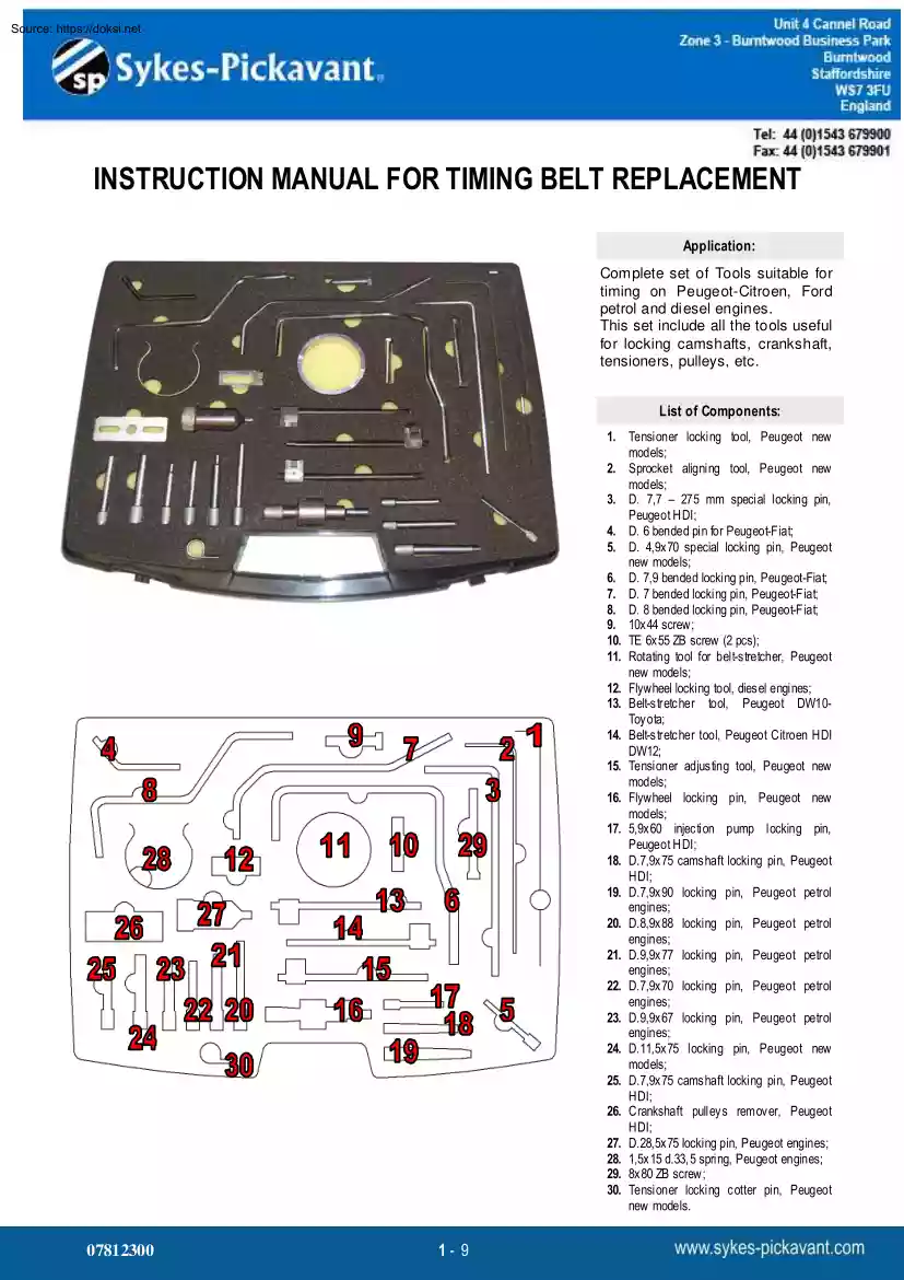
INSTRUCTION MANUAL FOR TIMING BELT REPLACEMENT Application: Complete set of Tools suitable for timing on Peugeot-Citroen, Ford petrol and diesel engines. This set include all the tools useful for locking camshafts, crankshaft, tensioners, pulleys, etc. List of Components: 1. Tensioner locking tool, Peugeot new models; 2. Sprocket aligning tool, Peugeot new models; 3. D 7,7 – 275 mm special locking pin, Peugeot HDI; 4. D 6 bended pin for Peugeot-Fiat; 5. D 4,9x70 special locking pin, Peugeot new models; 6. D 7,9 bended locking pin, Peugeot-Fiat; 7. D 7 bended locking pin, Peugeot-Fiat; 8. D 8 bended locking pin, Peugeot-Fiat; 9. 10x44 screw; 10. TE 6x55 ZB screw (2 pcs); 11. Rotating tool for belt-stretcher, Peugeot new models; 12. Flywheel locking tool, diesel engines; 13. Belt-stretcher tool, Peugeot DW10Toyota; 14. Belt-stretcher tool, Peugeot Citroen HDI DW12; 15. Tensioner adjusting tool, Peugeot new models; 16. Flywheel locking pin, Peugeot new models; 17. 5,9x60 injection pump
locking pin, Peugeot HDI; 18. D7,9x75 camshaft locking pin, Peugeot HDI; 19. D7,9x90 locking pin, Peugeot petrol engines; 20. D8,9x88 locking pin, Peugeot petrol engines; 21. D9,9x77 locking pin, Peugeot petrol engines; 22. D7,9x70 locking pin, Peugeot petrol engines; 23. D9,9x67 locking pin, Peugeot petrol engines; 24. D11,5x75 locking pin, Peugeot new models; 25. D7,9x75 camshaft locking pin, Peugeot HDI; 26. Crankshaft pulleys remover, Peugeot HDI; 27. D28,5x75 locking pin, Peugeot engines; 28. 1,5x15 d33, 5 spring, Peugeot engines; 29. 8x80 ZB screw; 30. Tensioner locking cotter pin, Peugeot new models. 07812300 1- 9 Diesel & Gasoline Engines: Fiat: Ulisse Ford: Fiesta Fusion Focus Focus C-Max Citroen & Peugeot: Xsara, C2, C3, C4, C5, C8 E vasion,Berlingo, Xsara, Xs ara/Picasso, Xantia, E vasion, C5, 206,306, 307, 406, 407, 607, 806 Engine s: 1.4 -16 Hdi, 14 -1 6 Duratorq TDCi, 18-20EW, 19 D, 20 Hdi, 20 JTD, 2,2 Hdi, 1.8 16v, 20 16v Code s: DV4TD
(8HW/8HX/8HZ) - DV4TE D4 (8HV/8HY )- DV 6A TED4 (9HX/9HY/9HZ) F6JA -F6JB-F6JC-G8DA-G8DB-EW7J4(6FZ) - EW10J4 (RFN/ RFR) EW10J4S (RFK)-EW10-HPi (RLZ)- EW12 (3FZ), DW8 (W JZ), DW10(RHY -RHZ), DW12 (4HX), EW7J4 (6FZ), EW10J4 (RFR),EW10J4D (RLZ) – Hpi Diesel Engines: 1.4 – 16 HDi, TDCi Ford Models Fiesta Fusion Focus Focus C-Max Engines 1.4 -16 Duratorq TDCi Codes DV4TD (8HW/8HX/8HZ), DV4TED4 (8HV/8HY), DV6ATED4 (9HX/9HY/9HZ) F6JA, F6JB, F6JC, G8DA, G8DB Citroen Models Xsara, C2, C3, C4, C5, C8 Evasion Engines 1.4 -16 Hdi, 18-20 EW Codes DV4TD (8HW/8HX/8HZ), DV4TED4 (8HV/8HY), DV6ATED4 (9HX/9HY/9HZ) F6JA, F6JB, F6JC, G8DA, G8DB EW7J4(6FZ), EW10J4 (RFN/RFR), EW10J4S (RFK), EW10-HPi (RLZ), EW12 (3FZ) Description: 1. Cranckshaft locking pin 6. Locking tool for belt-stretcher 2. Camshaft locking pin 7. Locking flywheel/clutch pin 3. Belt tensioner 8. Timing tool for belt-stretcher 4. Locking fuel pump pin 9. Locking pin for camshaft Peugeot Models 206, 307, 406, 406
Coupe, 607, 806, 807, Expert Engines 1.4 -16 Hdi, 18-20 EW Codes DV4TD (8HW/8HX/8HZ), DV4TED4 (8HV/8HY), DV6ATED4 (9HX/9HY/9HZ) F6JA, F6JB, F6JC, G8DA, G8DB EW7J4(6FZ), EW10J4 (RFN/RFR), EW10J4S (RFK), EW10-HPi (RLZ), EW12 (3FZ) 5. Locking tool 07812300 2- 9 Diesel Engine: 1.4 – 16 HDi, TDCi Ref. B Fig. 1 • Use the flywheel locking pin (n.1) to lock crankshaft position (see Re. A); • Now remove the crankshaft pulley; • Remove flywheel locking pin (n.1); • Mount the crankshaft pulley bolt; • Slowly rotate the crankshaft clockwise to align the camshaft pulley hole (see Re. B); • Use the camshaft locking pin (n. 2) • Use the crankshaft locking pin (n.4) (see Re C); • Now loosen the belt-stretcher with tensioner (n.3, or a 6 mm. hex key) and remove crankshaft pulley, crankshaft locking pin, tone wheel, timing belt. Ref. D Instruction for a right assembling: N.B Mount only new belt and operate with cold engine Ref. E Ref. C Ref. A Ref. C 07812300 •
Locking pin for camshaft (n.2) have to be mounted; • Use the timing pin for locking the fuel pulley (n.4, Re D); • Now mount the new timing belt on the pulley; then tone wheel, crankshaft pulley bolt by hand; • Remove pin (n.4), and mount it for locking crankshaft (Re. C); • Now start rotating anti-clockwise till you can see the sign in the window (Re. E); • Tighten the belt-stretcher at 30 Nm; • Remove crankshaft pin n.3, and camshaft pin n2; • Slowly rotate the crankshaft full turn 10 times; • Mount again crankshaft pin n.3 and check if camshaft pin could be inserted. • Now remove all tools and mount all components; Ref. B Ref. D 3- 9 Ref. E Diesel Engines: DW8 – DW10 – DW12 (Hdi) Citroёn Berlingo, Xsara DW8 (WJZ) 1.9 D Xsara/Picasso, Xantia, Evasion, C5 DW10 (RHY-RHZ) 2.0 HDi C5 DW12 (4HX) 2.2 HDi Fiat Ulisse DW10 (RH Z) 2.0 JTD Peugeot Description: 1. TDC Flywheel lock pin 6. Lock pin for crankshaft 2. TDC Flywheel lock pin 7. Lock pin
for injection pump 3. TDC Flywheel lock pin 8. Extractor for crankshaft pulley 4. Bel tensioner DW8-DW10 9. Lock clip for timing belt 5. Belt tensioner DW12 10. Flywheel locker 11. Camshaft clamp bolt 206-306 206, 306, 307, 406, 607, 806 DW8 (WJZ) 1.9 D DW10 (RHY-RHZ) 2.0 HDi 406, 407 DW12 (4HX) 2.2 HDi • The angular displacement of the sprockets do not have to exceed the space of a cog • Fit the belt on the water pump pulley and on the belt tensioner, then loosen the belt tensioner bolt. • Turn the belt tensioner pulley clockw ise with the wrench supplied (re. 4) in order to stretch the belt • Tighten slightly the bolts w ith a couple of 10 N m • Remove the clip (re. 9) • Rotate the belt tensioner pulley anticlockw ise till the tension reaches ENGINE 1,9 D - WJZ (DW8), WJY(DW8B) 106±2 units SEEM. • Tighten the belt tensioner bolt w ith a couple of 21 N m. • • • • • • • • • • • • • Disassembling: Rotate the crankshaft clockwise
into the adjusting position Insert the flywheel timing pin (re. 2 ) Insert the camshaft clamp bolt (re. 11) Insert the injection pump lock pin (re. 7) Loosen the bolt of the belt tensioner and rotate the pulley clockwise going away from the belt Tighten slightly the bolt and remove the timing belt • The bolts have not to be at the end of grooves on the sprockets. Assembling: Loosen the bolts of the camshaft pulley, tighten w ith the fingers and loosen of 1/6 of turn Rotate the pulley completely clockw ise Loosen the bolts of the injection pump pulley, tighten with the fingers and then loosen of 1/6 of turn. Rotate completely the pulley of the injection pump clockwise Put on the belt on the crankshaft pulley and lock it with a clip (re. 9) Fit the timing belt anticlockw ise. It must be stretched on the sprockets. Assemble the belt on the cogs of the injection pump and then of and belt tensioner bolts. • Tighten the bolts of the camshaft pulleys and of the injection pump with a
couple of 23 N m. • Remove the timing and lock pins. • Make the crankshaft 8 revolutions made clockwise reaching the adjusting position • Reinser t the tools (re. 2, 7 and 11) and loosen the crack- camshaft • Measure the belt tension rotating the pulley anticlockwise till about 42±2 units SEEM • Tighten the belt tensioner bolt w ith a couple of 21 N m • Tighten the camshaft bolts w ith a couple of 23 N m • Remove and then reinstall the tension meter: it must indicate 38-46 units SEEM • Remove the meter and the lock and timing pins • Rotate the crankshaft twice clockwise in the adjusting position • Tighten the bolt of the crankshaft pulley at a couple of 40 N m + 51° the crankshaft pulley 07812300 4- 9 ENGINE: 2,0 Hdi - RHY (DW10ADT), RHZ (DW10ATED/L) Disassembling: • Insert the flywheel locker (re. 10) • Remove the bolts of the crankshaft pulley and then the pulley using the tool re. 8 • Remove the flywheel locker (re. 10) • Disconnect the supply
connections, support the engine and the power steering tank, the engine suppor ts on the right and the timing guard. • Turn the crankshaft clockw ise in the adjusting position • Insert the TDC flywheel lock pin (ref. 2 , 1 or 3 for C5 ) • Insert the crankshaft lock pin (rif. 6) • Loosen the bolt of the belt tensioner and of the crankshaft pulley • Rotate the belt tensioner pulley clockwise going away from the belt with using the tool re. 5 • Tighten slightly the bolt and remove the timing belt Assembling: • Loosen the bolts of the camshaft pulley, tighten with the finger s and loosen of 1/6 of turn • Rotate the pulley completely clockw ise • Put on the belt on the crankshaft pulley and lock with the clip re. 9 • Fit the timing belt anticlockwise. It must be stretched on the sprockets. • Assemble the belt on the cogs of the injection pump and then of the crankshaft pulley • The angular displacement of the sprockets do not have to exceed the space of a cog •
Fit the belt on the water pump pulley and on the belt tensioner, then loosen the belt tensioner bolt. • Turn the belt tensioner pulley clockw ise with the wrench supplied (re. 5) in order to stretch the belt • Reinser t the tools (re. 2 and 6) and loosen the crack-camshaft and belt tensioner bolts. • Tighten slightly the bolts w ith a couple of 10 N m • Remove the clip (re. 9) • Measure the belt tension rotating the pulley anticlockwise till abou t • Install the belt tensioner meter in the position ▼ 54±2 units SEEM • Rotate the belt tensioner pulley anticlockw ise till the tension reaches • Tighten the belt tensioner bolt w ith a couple of 25 N m 98±2 units SEEM. • Tighten the camshaft bolts w ith a couple of 20 N m • Tighten the belt tensioner bolt w ith a couple of 25 N m. • Remove and then reinstall the tension meter: it must indicate 51- • The bolts have not to be at the end of grooves on the sprockets. 57 units SEEM, except for C5 that has
to indicate • Tighten the bolts of the camshaft pulleys and of the injection pump SEEM. 54±3 units with a couple of 20 N m. • Remove the meter and the lock and timing pins • Remove the timing and lock pins. • Rotate the crankshaft twice clockwise in the adjusting position • Make the crankshaft 8 revolutions made clockwise reaching the adjusting position 07812300 5- 9 • Tighten the bolt of the crankshaft pulley at a couple of 40 N m + 51° ENGINE: 2,2 Hdi - 4HX (DW12ATED) Disassembling: • Rotate the crankshaft clockwise into the adjusting position • Insert the flywheel timing pin (re. 3 ) • Insert the camshaft clamp bolt (re. 6) • Loosen the bolt of the belt tensioner and of the camshaft pulley • Rotate the belt tensioner pulley clockwise going away from the belt with using the tool re. 4 • Tighten slightly the bolt and remove the timing belt Assembling: • Rotate the pulley completely clockw ise • Put on the belt on the crankshaft pulley and
lock with the clip re. 9 • Fit the timing belt anticlockw ise. It must be stretched on the sprockets. • Assemble the belt on the cogs of the injection pump and then of the crankshaft pulley • The angular displacement of the sprockets do not have to exceed the space of a cog • Fit the belt on the water pump pulley and on the belt tensioner, then Warning: Align the black links “A” of the timing belt with the cogs marked “B” of the camshaft sprocket. loosen the belt tensioner bolt. • Turn the belt tensioner pulley clockwise with the wrench supplied (re. 4) in order to stretch the belt • Tighten slightly the bolts w ith a couple of 10 N m • Remove the clip (re. 9) • Install the belt tensioner meter in the position ▼ • Rotate the belt tensioner pulley anticlockwise till the tension reaches 106±2 units SEEM. • Tighten the belt tensioner bolt w ith a couple of 25 N m. • The bolts have not to be at the end of grooves on the sprockets. • Tighten the bolts
of the camshaft pulleys and of the injection pump with a couple of 20 N m. • Remove the timing and lock pins. • Make the crankshaft 8 revolutions made clockwise reaching the adjusting position • Reinser t the tools (re. 6) and loosen the crack-camshaft and belt tensioner bolts • Measure the belt tension rotating the pulley anticlockwise till about 51±3 units SEEM • Tighten the belt tensioner bolt w ith a couple of 25 N m • Tighten the camshaft bolts w ith a couple of 20 N m • Remove and then reinstall the tension meter: it must indicate 51±3 units SEEM. • Remove the meter and the lock and timing pins • Rotate the crankshaft twice clockwise in the adjusting position • Tighten the bolt of the crankshaft pulley at a couple of 70 N m + 51° • Lock the crankshaft pulley bolt w ith a couple of 260 N m 07812300 6- 9 Gasoline Engines: Citroёn - Peugeot “EW” 16v. Petrol Engine: 1.8 – 20 twin cam Ref. A • Rotate the crankshaft clockwise till timing position
namely when it is possible to insert the locking flywheel/clutch pin (n. 7, Ref B); • Insert now the camshaft locking pins (Ref. A); Ref. E • Remove crankshaft pulley bolt, the pulley and lower timing guard; • Loosen the belt-stretcher bolt and rotate clockwise the pulley with tensioner supplied (n.3, or with 6mm hex key, Ref. C Re. C); then remove timing belt; Instruction for a right assembling: N.B Fit only new belt and operate with cold engine Ref. D • Check good functioning of belt-stretcher pulley and guide pulley; • Check good functioning of water pump pulley; • Flywheel tool (n. 7) and camshaft pins have to remain fitted; • Fit now the timing tool (n. 8) on belt-stretcher pulley (Ref D); • Rotate the pulley clockwise to make the arrow crossing the Ref. A sign (Ref. E-1); • Fit the locking tool (n. 6) on belt-stretcher pulley (Ref D); • Remove now the timing tool (n. 8) on belt-stretcher pulley; • Put timing belt on the crankshaft pulley; • Now
Fit timing belt as follow: 1) guide pulley, 2) inductions stroke camshaft, 3) unloading stroke camshaft, 4) water Rif. A Rif. A pump pulley, 5) belt-stretcher pulley; • Remove camshaft unloading stroke locking pin and locking tool (n. 6); • Fit the lower timing guard and crankshaft pulley; • Tighten crankshaft pulley at 40±4 Nm +53°; • Rotate belt-stretching pulley anti-clockwise till arrow rich an angle of 10°, see displayed position (Ref. E-2); • Now rotate clockwise till when the arrow and sign are Ref. C Rif. D aligned (Ref. E-3); • Tighten belt-stretcher bolt at 17-23 Nm; • Now remove locking tool (n. 7) and inductions stroke camshaft locking tool; • Slowly rotate clockwise the crankshaft full turn 10 times to timing position; • Fit inductions stroke camshaft locking pin; • Check on the belt-stretcher that arrow and sign are aligned; • Remove inductions stroke camshaft locking pin. 07812300 7- 9 Citroёn C5-Xara-Xara Picasso 1.8 16v EW7J4
(6FZ) 2.0 16v EW10J4 (RFR) 2.0 16v EW10J4D (RLZ) – HPi Peugeot 206-207-306-307 406-407 Description: 1. Flywheel locking pin; 2. Locking pin for camshaft pulley; 3. Locking pin for crankshaft pulley; 4. Clip for the belt locking; 5. Tensioner pin: 6. Locking pin for camshaft pulley (HPi); 7. Crankshaft locking pin Disassembling • Rotate the crankshaft clockwise and position for the adjustment; • Insert the crankshaft locking pin (re. A); • Now insert the camshafts pulleys locking pins (re. B–C); • Loosen the belt tensioner bolt (re. D); • Turn the belt tensioner clockw ise (re. E); • Remove the timing belt. 07812300 8- 9 2.0 16v EW10J4 (RFR) 1.8 16v EW7J4 (6FZ) 2.0 16v EW10J4 (RFR) 2.0 16v EW10J4D (RLZ) - HPi Assembling • Fix the locking pins correctly (re. A-B-C) • Assemble the new timing belt on the crankshaft pulley anticlockwise. • Insert the clip on the crankshaft pulley (re. F) • Put on the belt anticlockwise, verify that it is stretched on the
sprockets well. • Remove all the locking pins and the clip (re. A-B-C-F) • Rotate the timing belt pulley w ith a socket wrench (re. E) anticlockwise until the indicator (re. G) reach the position re H – Beware: the array has to overcome the notch (re. I) at least of 10°. If this dose not happened, replace the bel t tensioner. • Rotate the timing belt pulley clockwise until the indicator and the notch are aligned (re. I) – Beware – if the indicator overcome the notch (re. I), repeat the assembling operations • Tighten the belt tensioner bolt w ith a couple of 21 N m. (re L) • Turn the crankshaft 10 times clockwise and position for the adjustment. • Insert the timing pin of the aspiration camshaft (re. C) • Insert the timing pins (re. A-B-C) • Tighten the crankshaft bolt with a couple of 40 N m. • Remove the locker and all the pins. 07812300 9- 9
 Just like you draw up a plan when you’re going to war, building a house, or even going on vacation, you need to draw up a plan for your business. This tutorial will help you to clearly see where you are and make it possible to understand where you’re going.