A doksi online olvasásához kérlek jelentkezz be!
A doksi online olvasásához kérlek jelentkezz be!
Nincs még értékelés. Legyél Te az első!
Legnépszerűbb doksik ebben a kategóriában


Tartalmi kivonat
Automated Test Generation for Computer Telephony Systems Brian C. Miller Teradyne Software and System Test 44 Simon Street, Nashua, NH 03060 miller.brian@teradynecom Introduction Current Design and Test Process Design Process Significant progress has been made in automating the frontend application design process and back-end test execution for today’s Computer Telephony applications. Sophisticated application builder tools coupled with configurable Interactive Voice Response (IVR ) platforms allow end users, integrators, VARs or dealers to build sophisticated IVR applications. Robust automated test execution systems can automatically emulate protocols and voice to greatly increase the thoroughness and repeatability of functional test, load testing, regression testing and in-service monitoring1 . Despite the automation in design and execution, the process for designing and implementing tests is still mostly manual and largely unchanged from what was done a decade ago. What’s
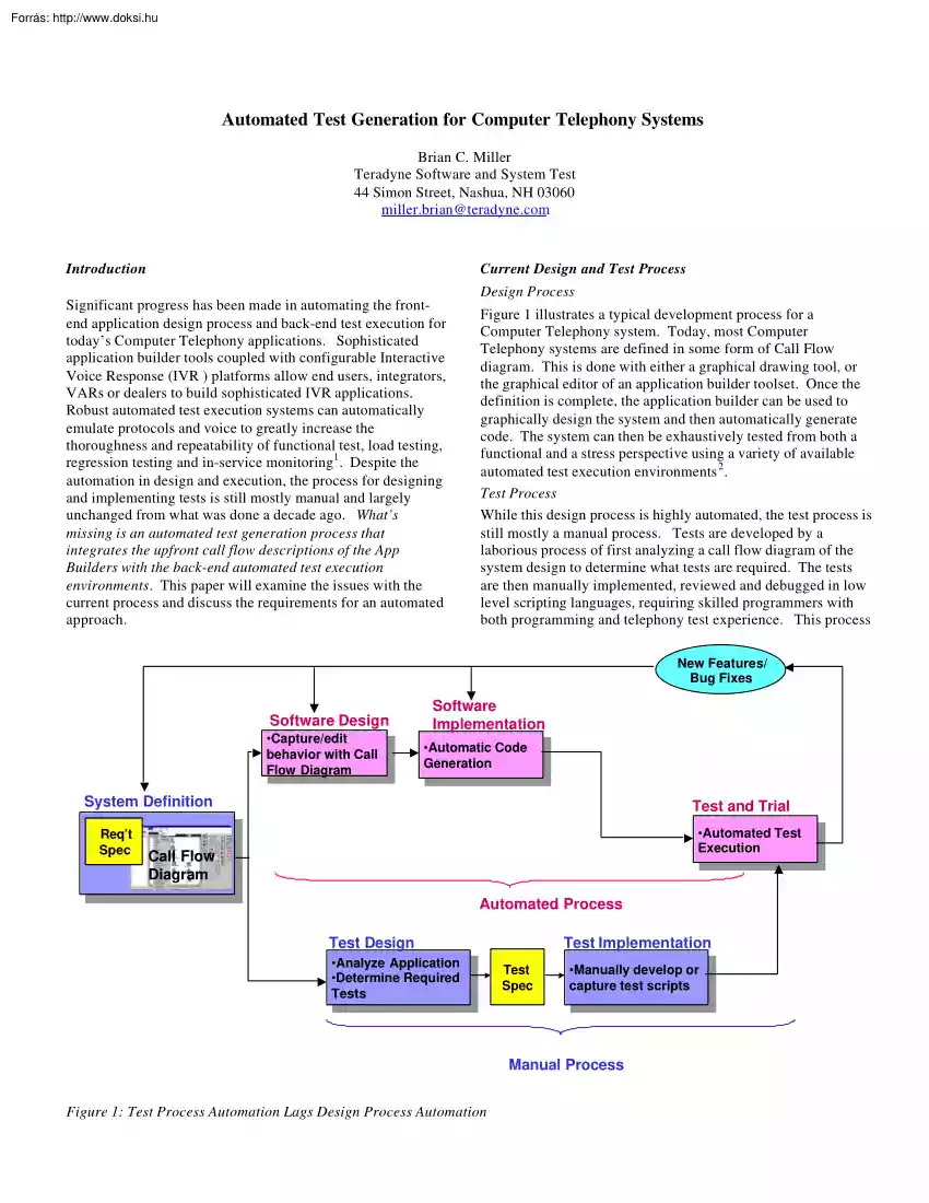
missing is an automated test generation process that integrates the upfront call flow descriptions of the App Builders with the back-end automated test execution environments. This paper will examine the issues with the current process and discuss the requirements for an automated approach. Figure 1 illustrates a typical development process for a Computer Telephony system. Today, most Computer Telephony systems are defined in some form of Call Flow diagram. This is done with either a graphical drawing tool, or the graphical editor of an application builder toolset. Once the definition is complete, the application builder can be used to graphically design the system and then automatically generate code. The system can then be exhaustively tested from both a functional and a stress perspective using a variety of available automated test execution environments 2 . Test Process While this design process is highly automated, the test process is still mostly a manual process. Tests are
developed by a laborious process of first analyzing a call flow diagram of the system design to determine what tests are required. The tests are then manually implemented, reviewed and debugged in low level scripting languages, requiring skilled programmers with both programming and telephony test experience. This process New Features/ Bug Fixes Software Design Software Implementation •Capture/edit •Capture/edit behavior with Call behavior with Call Flow FlowDiagram Diagram •Automatic Code •Automatic Code Generation Generation System Definition Req’t Spec Test and Trial •Automated •AutomatedTest Test Execution Execution Call Flow Diagram Automated Process Test Design •Analyze •AnalyzeApplication Application •Determine Required •Determine Required Tests Tests Test Implementation Test Spec •Manually develop or •Manually develop or capture test scripts capture test scripts Manual Process Figure 1: Test Process Automation Lags Design Process Automation
is repeated every time the application is updated or changed. At the end of the process there is no explicit measure of the test thoroughness. This can result in long field test cycles or worse, problems found by customers. behavioral modeling tools that can either find paths through the model, or validate specific use cases4 . The languages for these tools are complex and require skilled programmers to implement. Test is becoming the bottleneck There are several different approaches being used for automating the test implementation. All are based on having a set of re-useable test functions that are linked together to implement the actions of a single call path. At the simplest level, the functions are re-used by cutting and Features are released incrementally during the design process (Figure 2). The tests for each feature require a separate design and coding process. The time available for this process is being squeezed from two directions: • • Application builder tools
make it possible for new features to be added or changed quickly, making it difficult for the manual driven test process to keep up and creating a bottleneck. Market pressure is reducing the time for creating tests and increasing the need for new features. These features are implemented rapidly using automated application builder tools. Also, because of the time required to develop feature tests, little testing of feature interaction is done until late in the process. Problems found at this phase can be the result of a inaccurate requirement, poor design or an implementation error (Figure 1). Changes in the requirements require changes to the existing tests, further squeezing the process. Test Design •Analyze •AnalyzeApplication Application •Determine Required •Determine Required Tests Tests Test Implementation Test Spec •Manually develop or •Manually develop or capture test scripts capture test scripts • Behavioral Description Languages with path generation tools to
define scenarios • Description of Use Cases to be tested • Icon driven programming of parameterized functions • Paramaterized functions • Icon selected cut and paste • Cut and paste reuseable functions High level description of behavior with complex behavioral description language Definition of a single call flow paths using basic call flow icons Figure 3: A gap exists between the current automation tools used for test design and test implementation Features Product Development Life Cycle Define Design Implement Test and Trial Feature 1 QA Field Test Shrinking Mkt Windows from Increased Competition Rapid change Feature 2 made possible Feature 3 by design automation Feature n Design Code Execute Test Cycle 1. Difficult to keep pace with new features/changes, making test the bottleneck Result: 2. Little time for testing feature interaction until late in process, extending the time required for QA and field trials Figure 2: Rapid change and shrinking market
windows are squeezing the Test Development Process Available Test Automation Today there is a gap between automation tools used for test design and those used for test implementation. There are test design tools that model an application's behavior and then automatically find test paths through the model3 . Test implementation tools automate the creation of test scripts for a single call flow path, once it is defined. There is a gap in that the tools defining the test paths don't easily implement the code for those tests. In most cases, the link is a Test Specification defining the test paths that need to be implemented (Figure 3). The test design tools are sophisticated general-purpose pasting them into a new program using either an editor or clicking on an icon that automatically pastes the code. The script code is then hand edited to tweak it for new applications. A more sophisticated approach involves having parameterized functions that can be customized by modifying
parameter values. This reduces the need for modifying low level code and allows for a more generalpurpose library of functions. Implementing an Integrated Approach for Test Design and Implementation The gap between test design and test implementation tools can be filled by developing a set of re-useable call flow objects that can be used by the test design tools to model the behavior of the application and automatically find the test paths. By concatenating test execution code embedded in each re-useable object, the path generators in these test design tools can automatically implement the tests for each path found. To implement this kind of integrated approach, careful consideration should be given in defining the following: • A set of re-useable objects • A means of connecting the re-useable objects to represent the call flow • A methodology or algorithm for generating optimal test paths • An output format suitable for debug and documentation The remainder of this
paper will discuss the requirements for each of the above implementation steps. Defining Reusable Objects What objects are required? The first step in implementing an automated test generation solution is defining a set of re-useable objects that can be used to describe the behavior of a Computer Telephony application from a user interface perspective. The goal is to have a set of objects that a non-programmer can use to describe the application behavior. A starting point is found in the building blocks used by the design team's application builder tool. Unfortunately, depending on the tool, there could be 100's of building blocks. Many of these are operations internal to the design that an end user would not see (i.e, connect to database, string operations, file operations, etc.) Figure 4 illustrates a list of objects that Call Flow Object Description 1. Prompt-Response 2. Play Voice 3. Place Call 4. Record Voice play a greeting and receive a response play an audio file
make a phone call save voice data in a file 5. Go On-Hook 6. Go Off-Hook 7. Send Tones 8. Receive Tones 9. Wait For Hangup disconnect the call prepare to accept incoming calls send MF or DTMF tones receive MF or DTMF tones wait for call to be disconnected 10. Wait For Call 11. Wait For Energy 12. Wait for Silence 13. Recognize Speech 14. Reject Call wait for an incoming call wait for energy on line wait for silence on line compare speech data with a vocab reject incoming call on the line 15. Transfer Call 16. Error 17. Stop Channel 18. Send Fax 19. Receive Fax transfer a call to another number default error handler stop communications on the channel send a fax receive a fax Figure 4: Re-useable Call Flow objects must describe the behavior of a Computer Telephony application at the user interface would be needed to model at typical CT application at the interface level. In defining the library of re-useable objects, you should consider whether the objects are defined from an
application perspective or a test perspective. The application perspective is the same view a designer uses with an application builder tool. The test perspective is a mirror image of the application view, looking into the application from the tester. Test engineers use this perspective to think about what the tester is doing instead of how the application is reacting. As an example, a "Place Call" object in an application perspective (which causes the application to dial a number) is the equivalent of a "Receive Call" object in the test perspective, which causes the tester to receive an incoming call. The advantage of the applications perspective is that enables a direct mapping to the design call flow diagram and facilitates easier interaction with design engineers. The disadvantage is that it is an inside out view of the tests that are run, adding complexity to the test problem. In addition to defining a set of call flow objects that can represent the application
behavior, it may be necessary to develop additional specialized test objects. As an example, you may want to verify that the application responds properly when an end user dials ahead of the prompts. This could require some form of "listen and respond" object that sends digits a specified time after the prompt begins. It may also be necessary to develop objects that can capture and log various response data. Many applications are set up to have data dependent call flows. For example, an investment firm may want to have different customer call flows based account type or balance. An insurance company may want to route DNIS numbers from a disaster area directly to an agent. Testing these applications requires an object that enables data to be specified or imported. It may also be necessary to define objects that represent screen pops. Some applications have parallel processes that route a call to an agent while at the same time looking up an account balance in a database and
popping it on the screen of a designated agent. Implementing the Re-useable Objects Once the objects are defined, the first step in implementing them is to develop the code for executing the object action on the target test execution system. To make the object as general purpose as possible, this code should be parameterized to allow for broad re-use. Some of the parameters include digits to be dialed/received, voice prompts, telephony parameters and phone lines used. The code for the objects should also include default error handling routines. The objects also require a means of inputting the parameter values. Ideally, this should be done graphically with text boxes, buttons, or pull downs to enable use by nonprogrammers. Finally, there should be a means of providing specific test comments for documentation purposes. Creating the Call Flow Diagram Once the call flow objects are defined and implemented, there needs to be a method of connecting them together to model the
application behavior in the form of a call flow diagram. The ideal solution would be to import a call flow diagram directly from the chosen application builder tool. Unfortunately, there are no graphical interface standards for call flow diagrams to facilitate this. Also, since there is not a dominant supplier in this area, there are no third party solutions for integrating a call flow diagram of any application builder tool with any test design tool. Lacking the above, the best approach is to make it possible for a non-programmer to create a new call flow diagram that can easily be mapped to the design call flow diagram. To do this, it must be possible to enter the call flow diagram from the same application perspective used by the application builder tools (Figure 5). of a voicemail system where the main menu prompt and the call flow path will vary depending on the data values defined in the table. For example, a caller with "application access" turned off would not hear
the "press 6 for applications" prompt. If the 6 digit were then pressed, the caller would be routed to an error message. Finally, being able to specify hierarchical call flows enables a modular approach to test. Figure 6 illustrates a series of subcall flow diagrams that get branched to from the main menu Drawing all of these on a single flat call flow diagram would be hard to organize and even more difficult to read. Using hierarchy, the application can be decomposed to modular elements that can then be worked on in parallel. Additionally, having re-useable sub call flows allows the work to be leveraged across multiple platforms. If the sub call flow changes, the change can be implemented across all instances of the sub call flow with a single edit. In order to support data dependent call flows, the call flow diagram must be able to represent conditional branching dependent on data values. Figure 6 shows a call flow diagram Application View Test View Figure 5: An
application view is required for easy mapping to the design call flow diagram. Main Menu Main Menu If message in mailbox:(To listen to your messages, press 1.) If Send= 1 or 2: (To send a message, press 2.) To check receipt, press 3. To change your personal options, press 4. If Restart = Y: (To restart this session, press 5.) If Application Access= Y:(For applications, press 6.) To disconnect, press *. 1 2 3 4 5 6 R S CR PO RS AF 7,9,# 2,3,4,5,6 unprompted 8 * 0 Path thru call flow diagram depends on data values Goodbye You have pressed an incorrect key Your mailbox number is [xxxx) Disconnect Figure 6: Call Flow descriptions must support data dependencies and hierarchy Test Generation Requirements or added by editing the call flow diagram and using the path generator to rapidly create new tests. This has the greatest impact on new applications with volatile requirements, or in competitive situations where new features are frequently added. After the call flow
diagram is entered, the next step is to define an optimal set of test paths through the diagram. At a minimum, these test paths should accomplish the following: • Touch all elements of the call flow diagram(data and call flow objects) at least once. • Test for response to negative behavior. • Verify that illegal conditions can't occur. Achieving the above can be done either manually or automatically. In a manual approach, each path is separately constructed with the call flow objects and the code from each object is assembled to create a test script. Alternatively, using the path generation capability of a test design tool can automatically create the test paths. This approach offers several advantages: • Automatically create test paths that cover all objects. This is particularly important on large, complex call flows. Manually analyzing dozens of pages of call flows to determine the optimal set of test paths is tedious, time consuming and error prone. • Rapid
response to changes in the call flow diagram. Instead of editing low-level test scripts, tests are modified • Lower skill levels required to design tests. By reusing debugged call flow objects, non-technical people can enter diagrams for test engineers. The key issue in the using an automated path generator is to have the test paths that represent relevant applications scenarios and provide optimal test coverage. Having 100's or 1000's of tests on a part of the call flow happening 1% of the time may add nothing to quality and just decrease throughput. Figure 7 illustrates how different path generation algorithms can result in a varying number of paths through a diagram. A full cover algorithm, searching for all possible paths in the diagram, provides the most exhaustive coverage and the potential for the highest degree of error detection. Unfortunately, it may produce too many tests to practically execute. At the other end of the spectrum, a Quick Cover algorithm
provides broad functional coverage with a minimum number of paths by generating an optimal set of paths that touch each object at least once. When compared to a manual approach, this is typically more then enough. Some path generation tools enable the relative likelihood of each path to be specified so that the distribution of paths created is consistent with the operational behavior of the application. This assures that the test scripts created are relevant application scenarios. Path generation tools can also be used to generate optimal data sets for data driven applications. A model of the configuration options for the voicemail system in Figure 6 can result in anywhere from 5 to 2600 different combinations, depending on the coverage algorithm used. Test Documentation Ideally, the documentation for the test scripts should automatically be generated as a separate output whenever new test scripts are generated. This can be accomplished by having the generation tool concatenate
test descriptions annotated on each call flow object as it creates each path through the call flow diagram. This eliminates having an error prone separate step of documenting the scripts after they are generated. It also assures that the documentation is always in sync with the test scripts While debugging scripts it is also helpful to have a graphical display that shows the sequence of events on each channel for each test script. This sequence-based view simplifies review of the test scripts with other test or development engineers. Full Transition N-Switch Quick Profile 8 Paths 4 Paths 6 Paths 2 Paths User specified ACDFG ACDFH ACEFG ACEFH BCDFG BCDFH BCEFG BCEFH ACDFG ACDFH A C E F GorH B C DorE F GorH BCEFH BCEFG BCDFH BCDFG ACEFH ACDFG ACDFG BCEFH • • • Quick Cover – Least Paths. – Each Transition and State appears in at least one Path. N-Switch (N=1) – Intermediate number of Paths. – Each Transition “pair” (N+1, where N=1) appears in at
least one Path. Full Cover – Most Paths. – Each Transition and State appears in all contexts with every other Transition and State Figure 7: The number of paths created by a path generator depends on the algorithm used Summary Figure 8 summarizes the components of an automated solution discussed in this paper. The first step is to create a library of reuseable call flow objects that define the actions at the application’s user interface. These objects contain the code for executing the action on the target test execution environment. The objects are connected using a graphical editor to link the call flow objects together in the form of a call flow diagram. As the objects are placed, they are edited with comments describing the test action. Separate tables for data effecting the path through the call flow diagram must then be developed. Once the call flow diagram is completed, the test generator of an automated test design tool can be used to find paths through the call
flow diagram. As each path is found, the test execution code and test comments are concatenated together to automatically create test scripts and documentation. Implementing this approach can have a significant impact on the overall product development process by: • Reducing the time and skill level required to develop comprehensive test scripts • Allowing tests for feature changes or additions to be developed in minutes • Increasing the quality level by automatically generating comprehensive end to end tests across the entire call flow diagram. These benefits must be weighed against the cost developing or purchasing such a system. References Call data used across multiple objects Data Tables 1 Knowland, D., Life-Cycle Testing For Call Center Quality, CTI Management Magazine, December 1998 Test Documentation 2 Graphical Editor Path Generator Test Scripts Test Scheduling Gladstone, S., Testing Computer Telephony Systems and Networks, Flatiron Publishing, New York,
1994, ISBN 0936648-57-0 3 Call Flow Call Flow Object Call Flow Object Object Object Object Properties Object Properties Properties Re-useable Call Flow objects Test Execution Figure 8: Example of an integrated solution for automated Computer Telephony test generation Beizer, B., Black Box Testing, ,John Wiley & Sons, New York, 1995. ISBN 0-471-12094-4 4 Clarke, J., "Automated Test Generation from a Behavioral Model", Proceedings of the Software Quality Week 1998 Conference, 1998
 Apja V. István magyar király, anyja Erzsébet kun hercegnő volt. [1]László 1262-ben született Körösszegen. Bár IV. Béla és V. István ifjabb király éppen László születése évében kötött békét Pozsonyban, a két fél ellentéte 1264-ben újra fegyveres konfliktushoz vezetett. Az alig két éves Lászlót és édesanyját saját nagyapja fogatta el Sárospatakon, majd Túróc